Josh Starnes
-
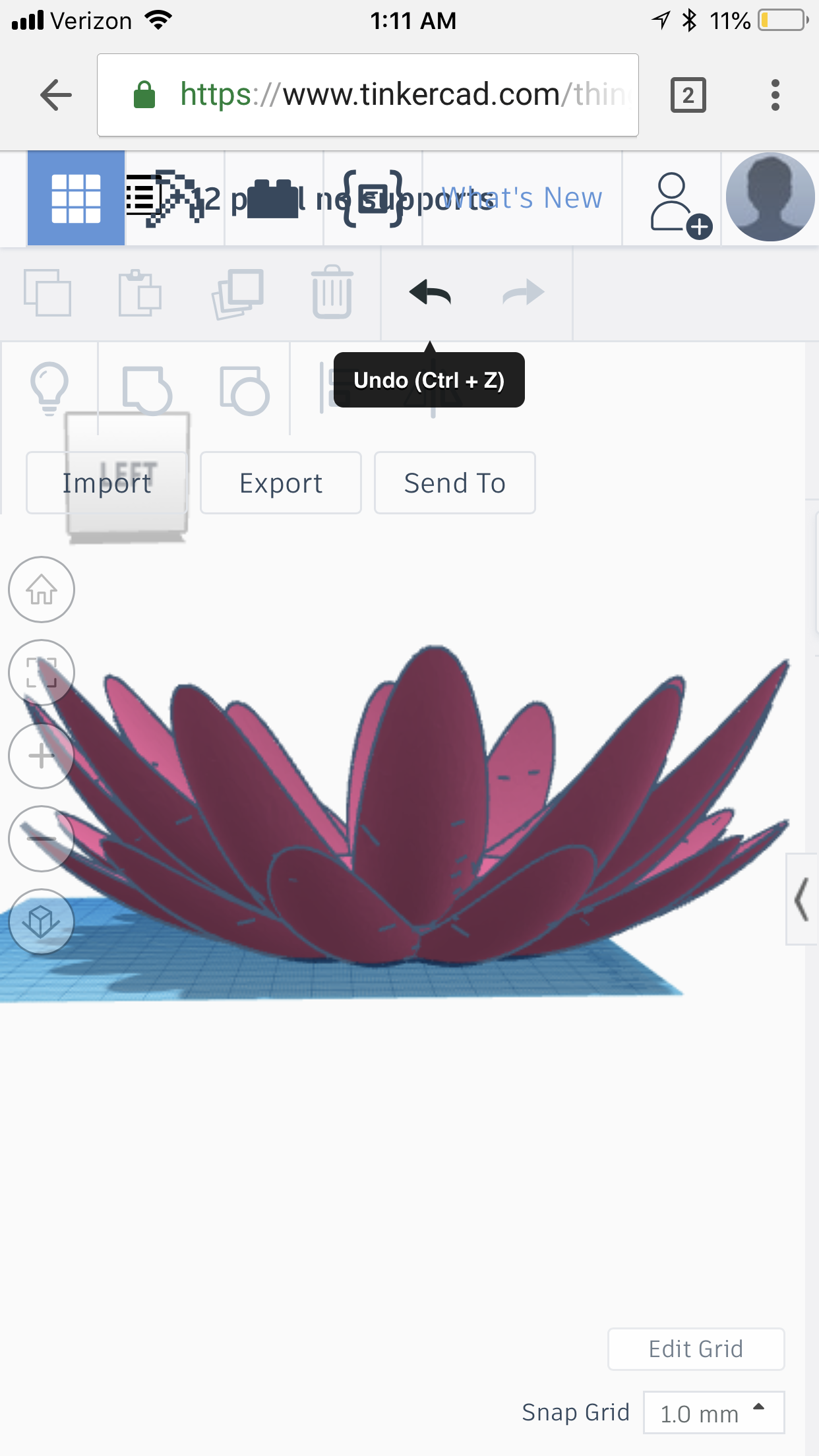
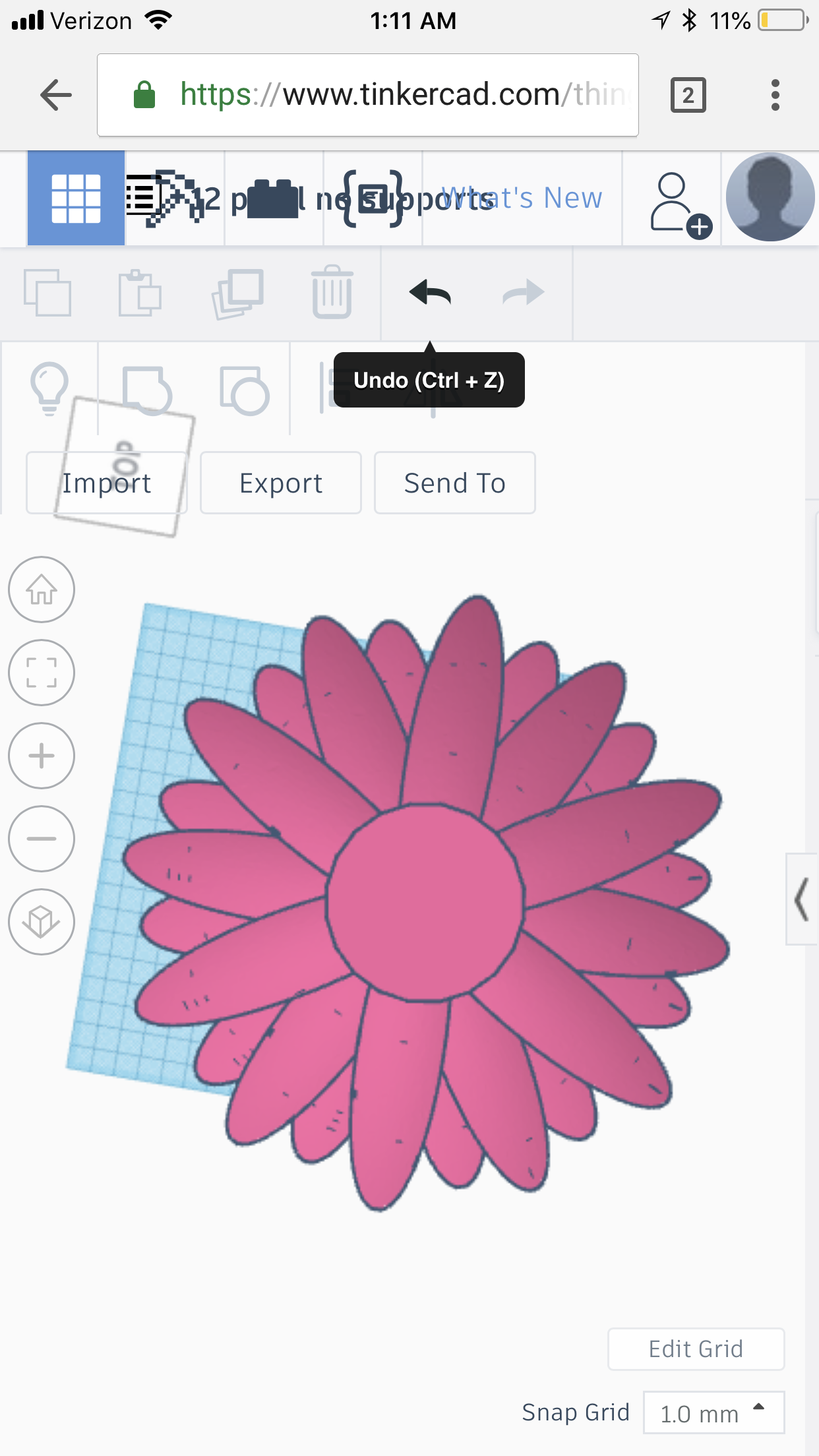
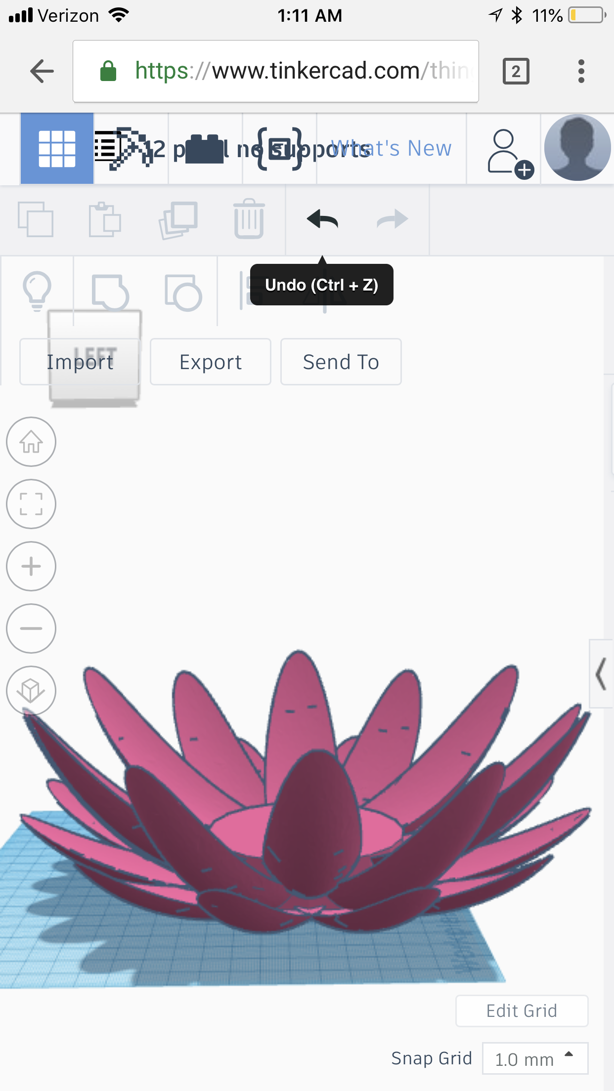
3d model loaded into files.
07/14/2018 at 19:00 • 0 commentsI am loading the 3d model into the files and even making a version with the cutouts for the heatsink and heat conductor already in the print. I needed to draw a beefy float to keep the flower above was as well that can also be 3d printed if you do not have 2 inch thick foam available for this project. The black box represents the heat conductor. I am considering using many copper 12 gauge wires in a bundle as the collector , but they will not be as good as a solid block, so this is a decision between look s versus performance. If you repeat my project this is a choice you will need to make yourself. The bottom box represents the CPU heatpipe cooler to handle the cold side of the TEG.
![]()
![]()
![]()
-
Multistage seeback information
07/13/2018 at 18:50 • 0 commentshttps://thermal.ferrotec.com/technology/thermoelectric-reference-guide/thermalref12/
12.0 Description & Modeling of Cascade Thermoelectric Modules
12.1 A standard single-stage thermoelectric cooling module is capable of achieving a maximum no-load temperature differential (DTmax) of approximately 72°C. It is possible to obtain DTs of up to 130°C by mechanically stacking modules on top of one another whereby the cold side of one module becomes the hot side of another module mounted above. This stacking arrangement is called a Cascade or Multi-Stage module configuration. Cascade modules usually, but not always, have a pyramid shape thereby the higher stages are physically smaller than those below. Regardless of the physical shape, however, lower stages must always have greater heat pumping capacity than the higher stages. although cascade configurations of up to six and seven stages have been constructed, practical cascade devices usually have from two to four stages.
The principal factor that limits cascade module performance is related to the temperature dependent properties of the thermoelectric semiconductor materials. The performance of Bismuth Telluride alloys used in most thermoelectric coolers generally peaks near 70°C and performance falls-off appreciably at lower temperatures. Consequently, cascade modules exhibit a condition of diminishing returns where, as successive stages are added, the increase in DT becomes smaller.
![]() Figure (12-1)
Figure (12-1)
Performance Graph of a Typical Cascade Module
12.2 MODELING OF CASCADE MODULES: Modeling of cascaded or multi-stage thermoelectric coolers is somewhat more complicated than for single-stage devices. With multi-stage coolers, the temperature between each stage is critically important and module performance cannot be established until each interstage temperature value is known. With a two-stage cooler only one interstage temperature must be determined but, as more stages are added, the thermal analysis becomes increasingly complex. Manually calculating multi-stage module performance is extremely laborious, yet with a computer, the required calculations can be performed with little effort.
The most common method for computer-modeling cascade modules involves carrying out an iterative series of performance calculations beginning with assumed interstage temperature values. Using this technique, the performance of each stage is repeatedly calculated until the difference between successive interstage temperature calculations becomes very small (typically 0.1°C or less). When this point is reached, each of the relevant module performance parameters can be ascertained. Note that the temperature-dependent value of SM, RM, and KM must be converted as explained in paragraph 11.2.4 to reflect the number of couples in each stage together with their optimum TE element currents. The following paragraphs describe the calculations needed to model two and three-stage cascaded thermoelectric modules. Four and greater-stage modules may be modeled in a similar manner by expanding the three-stage calculation routines to include terms for each additional stage. Calculations of the various parameters should be performed in the order shown.
12.2.1 TWO-STAGE MODULE CALCULATIONS: A typical two-stage thermoelectric module is illustrated in Figure (12-2). The following new terms will be used in the module performance calculations:
TM12 = the interstage temperature between stages 1 and 2 in °K SM1 = the Seebeck coefficient of the 1st stage in volts/°K SM2 = the Seebeck coefficient of the 2nd stage in volts/°K RM1 = the resistance of the 1st stage in ohms RM2 = the resistance of the 2nd stage in ohms KM1 = the thermal conductance of the 1st stage in watts/°K KM2 = the thermal conductance of the 2nd stage in watts/°K
![]() Figure (12-2) a) The interstage temperature (TM12) in °K is:
Figure (12-2) a) The interstage temperature (TM12) in °K is:(0.5 x I2) x (RM2 + RM1) + (KM1 x Th) + (KM2 x Tc) ____________________________________________________________ I x (SM1 – SM2) + KM1 + KM2
TM12 = b) Heat pumped (Qc) by the module in watts is:
Qc = (SM2 x Tc x I) – (0.5 x I2 x RM2) – (KM2 x (TM12 -Tc))
c) The input voltage (Vin) to the module in volts is:
Vin = (SM2 x (TM12 -Tc) + (I x RM2) + (SM1 x (Th – TM12)) + (I x RM1)
d) The electrical input power (Pin) to the module in watts is:
Pin = Vin x I
e) The heat rejected by the module (Qh) in watts is:
Qh = (SM1 x Th x I) + (0.5 x I2 x RM1) – (KM1 x (Th – TM12) or Qh = Qc – Pin
f) The coefficient of performance (COP) as a refrigerator is: COP = Qc / Pin
12.2.2 THREE-STAGE MODULE CALCULATIONS: A typical three-stage module is illustrated in Figure (12-3). The following new terms will be used in the module performance calculations:
TM23 = the interstage temperature between stages 2 and 3 in °K SM3 = the Seebeck coefficient of the 3rd stage in volts/°K RM3 = the resistance of the 3rd stage in ohms KM3 = the thermal conductance of the 3rd stage in watts/°K
![]() Figure (12-3) a) The lower interstage temperature (TM12) in °K is:
Figure (12-3) a) The lower interstage temperature (TM12) in °K is:(0.5 x I2 x (RM1 + RM2)) + (KM1 x Th) + (KM2 x TM23) __________________________________________________________ I x (SM1 – SM2) + KM1 + KM2
TM12 = b) The upper interstage temperature (TM23) in °K is:
(0.5 x I2 x (RM2 + RM3)) + (KM2 x TM12) + (KM3 x Tc) __________________________________________________________ I x (SM2 – SM3) + KM2 + KM3
TM23= c) Heat pumped by the module (Qc) in watts is:
Qc = (SM3 x Tc x I) – (0.5 x I2 x RM3) – (KM3 x (TM23 – Tc))
d) The input voltage (Vin) to the module in volts is:
Vin = (SM1 x (Th – TM12)) + (I x RM1) + (SM2 x (TM12 – TM23)) + (I x RM2) + (SM3 x (TM23 – Tc)) + (I x RM3)
e) The input power (Pin) to the module in watts is: Pin = Vin x I
f) The heat rejected by the module (Qh) in watts is: Qh = Qc + Pin
g) The coefficient of performance (COP) as a refrigerator is: COP = Qc / Pin
-
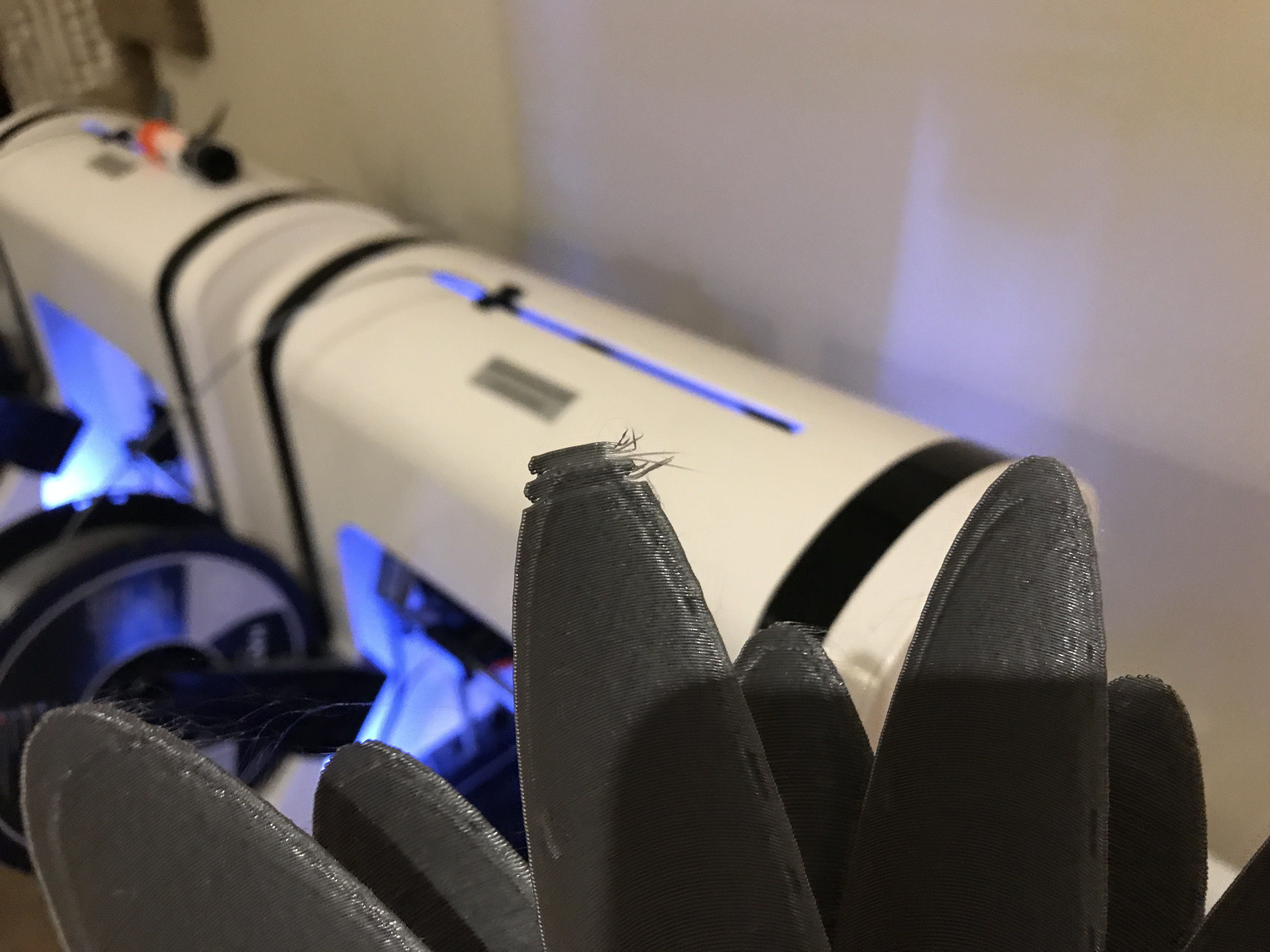
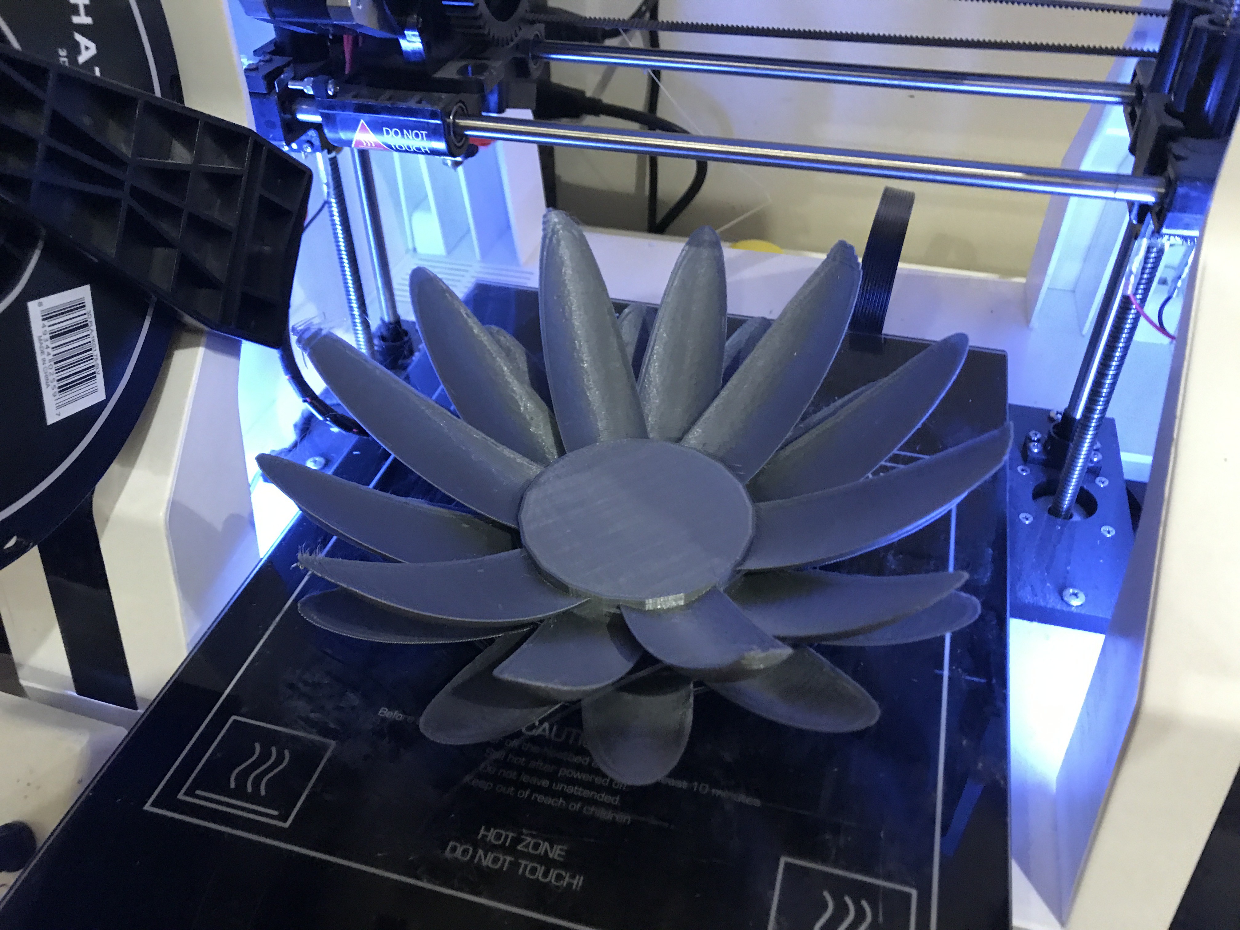
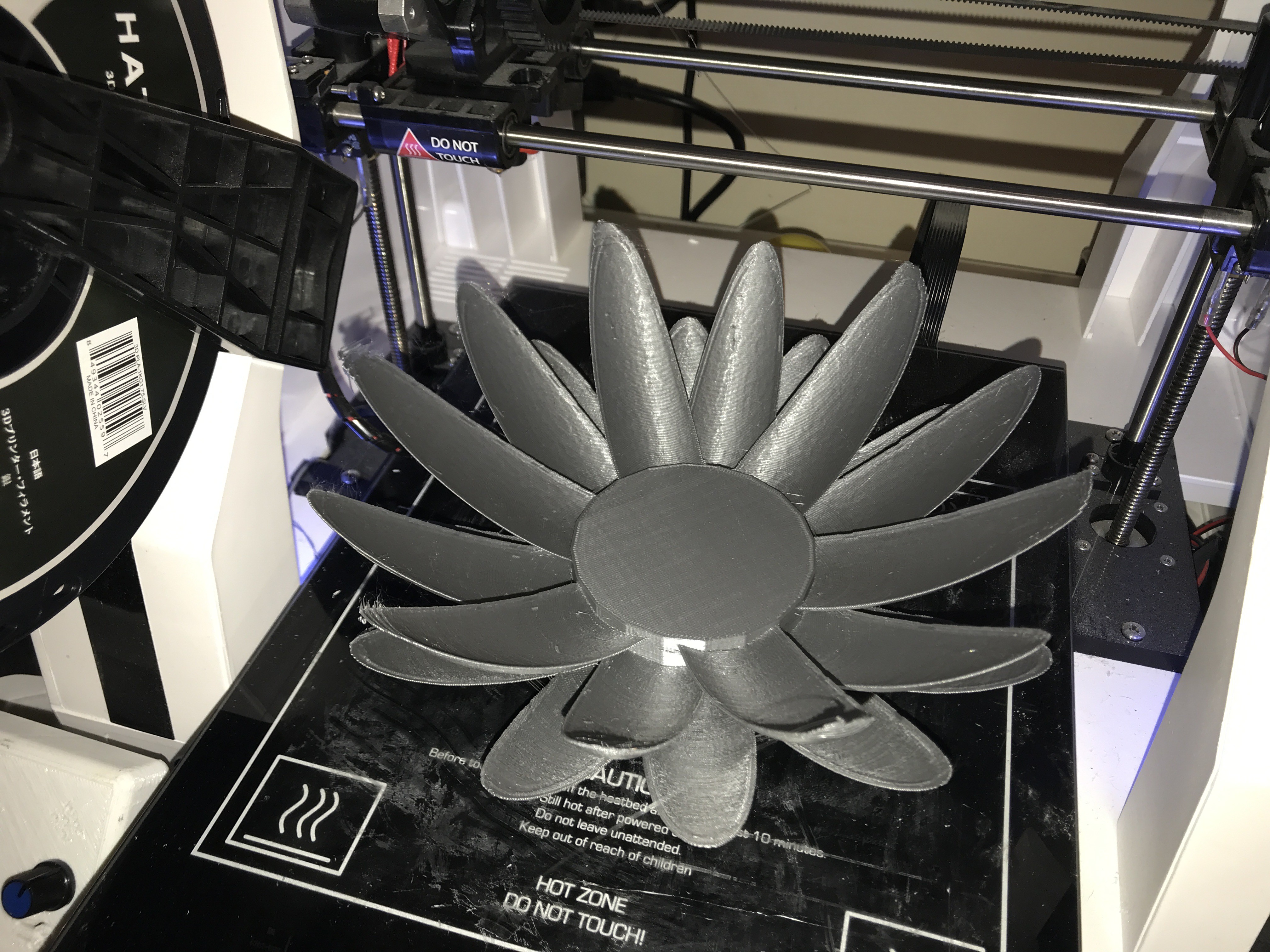
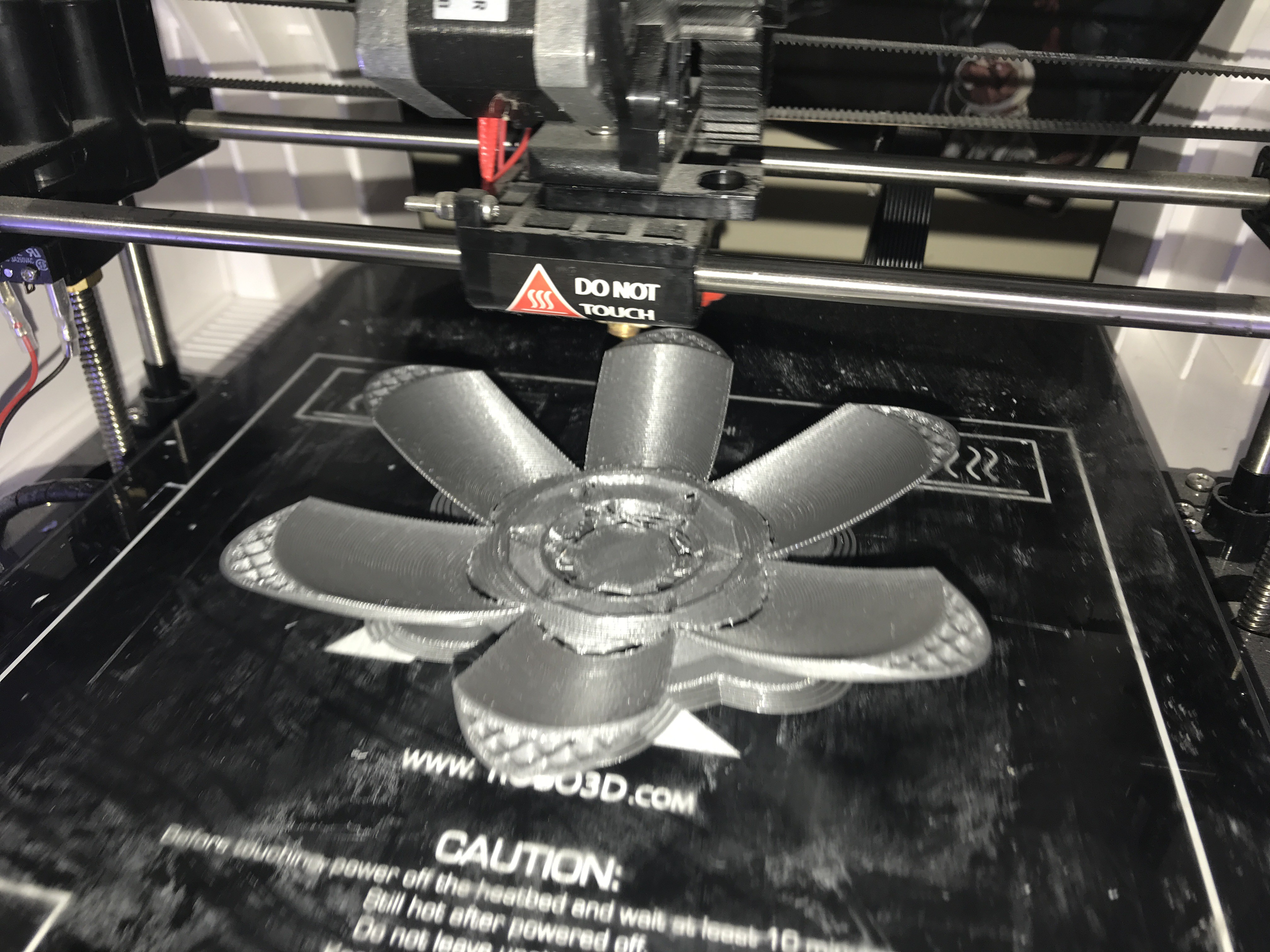
update
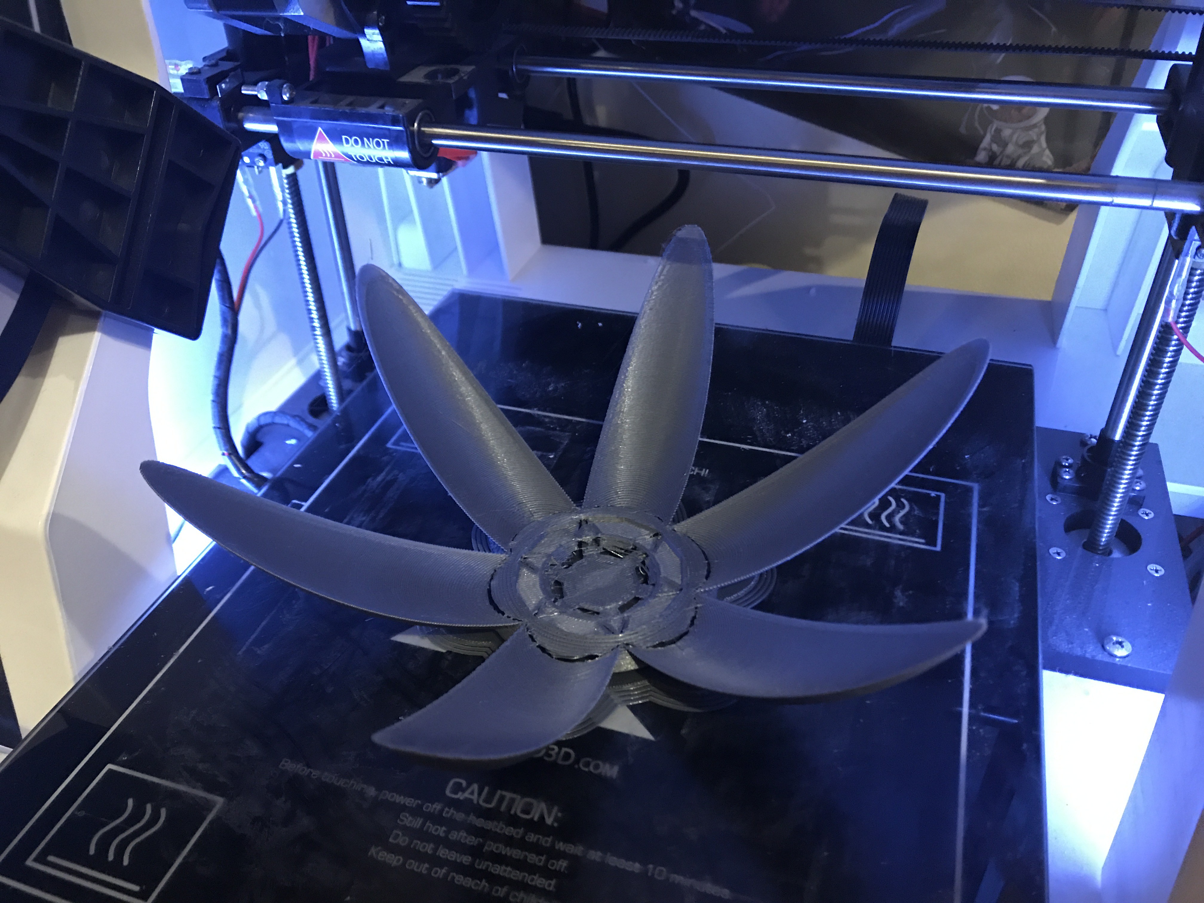
07/11/2018 at 14:01 • 0 commentsI printed the new flower model I put together, the edges ofcourse on a couple tips are wonky because I pushed the model too close to the edge of the bed and the print carriage hit the end stop. Such as Life. I did recieve the step up voltage converter and regulator for 5 volts 1 amp hour and the heatsing I planned to use on the bottom of the flower. On the other hand however I have NOT recieved the TEG modules I ordered, they missed my location and went to another city, they are on their way back now and I expect them today. Lets cross our fingers :)
-
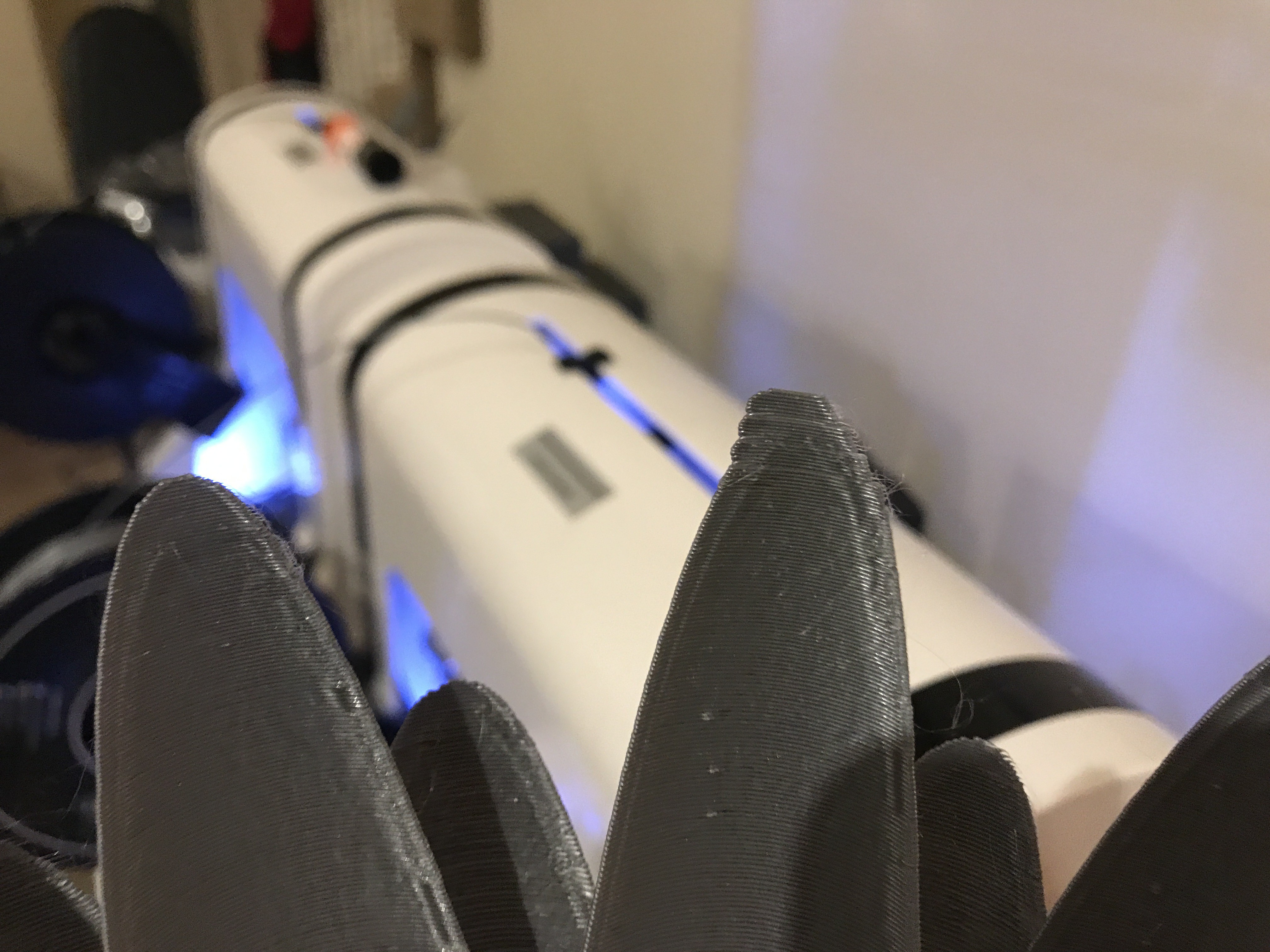
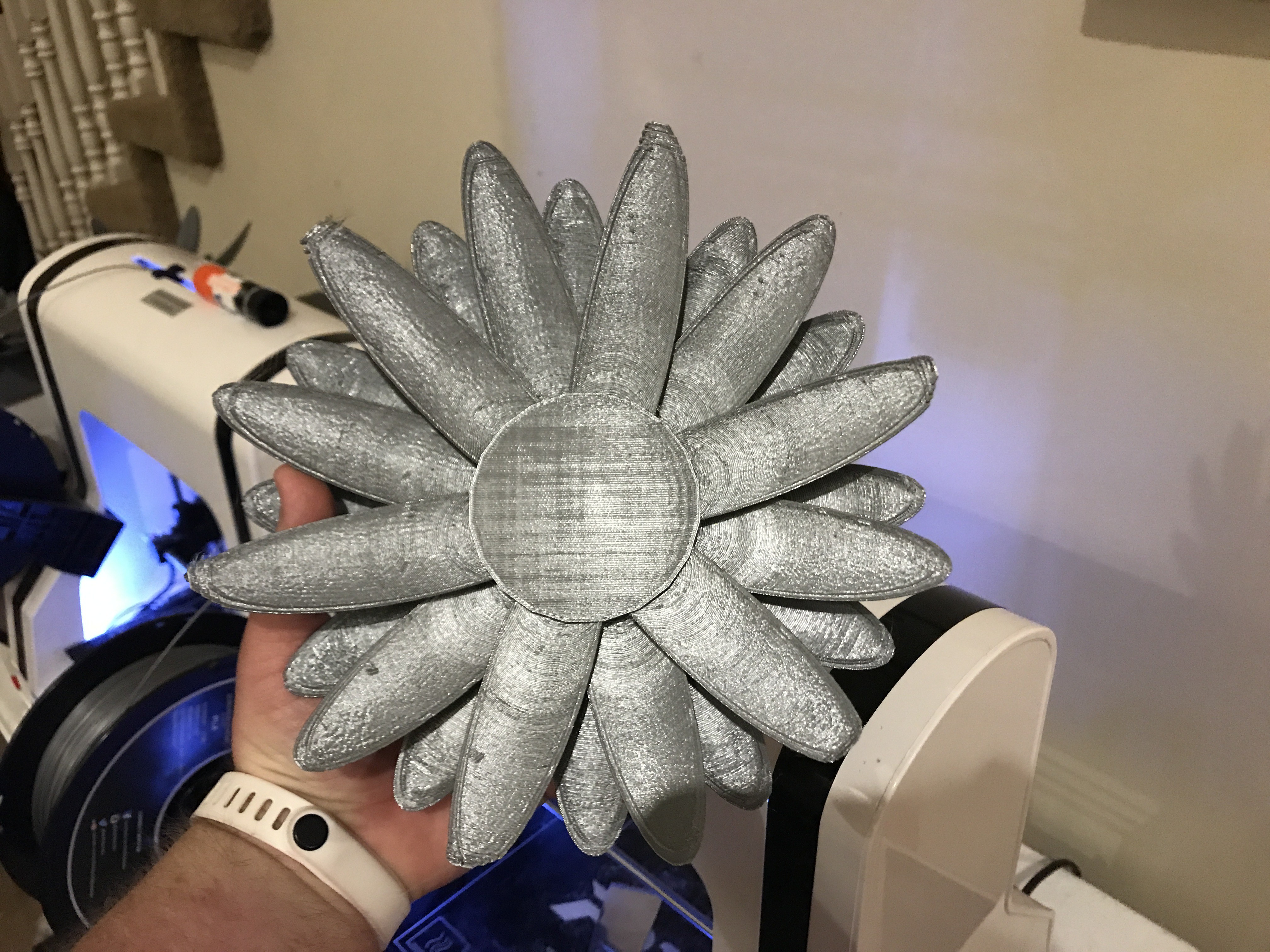
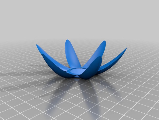
Reflective surfaces
07/10/2018 at 03:18 • 0 comments![]()
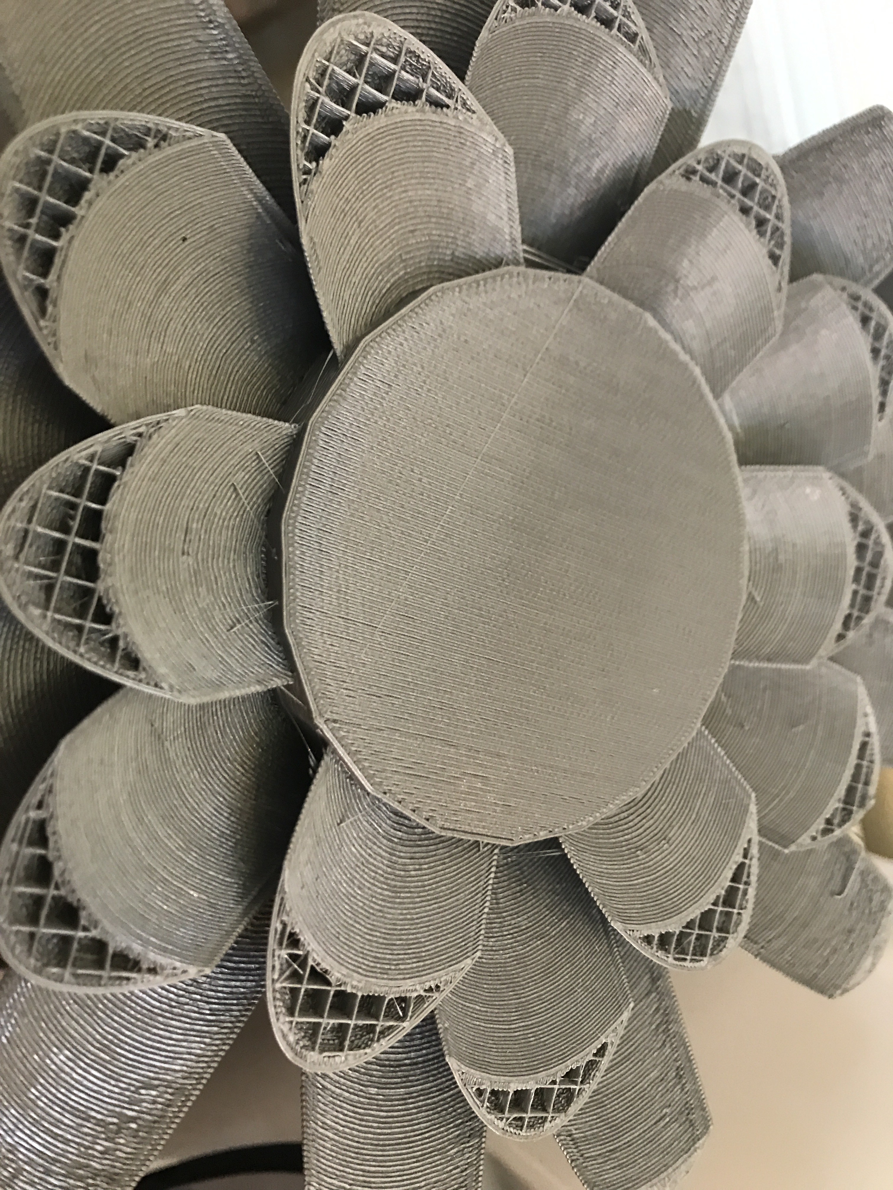
When you look directly at the flower you can see the angles of the petals reflect light. Once Mylar reflective film is covering the leaves this should reflect heat to the center like a mini solar oven.
-
Version 2 printed
07/10/2018 at 03:15 • 0 comments![]()
![]()
![]()
![]()
![]()
-
Version 2 lily misprint but some good news
07/10/2018 at 02:06 • 0 comments![]()
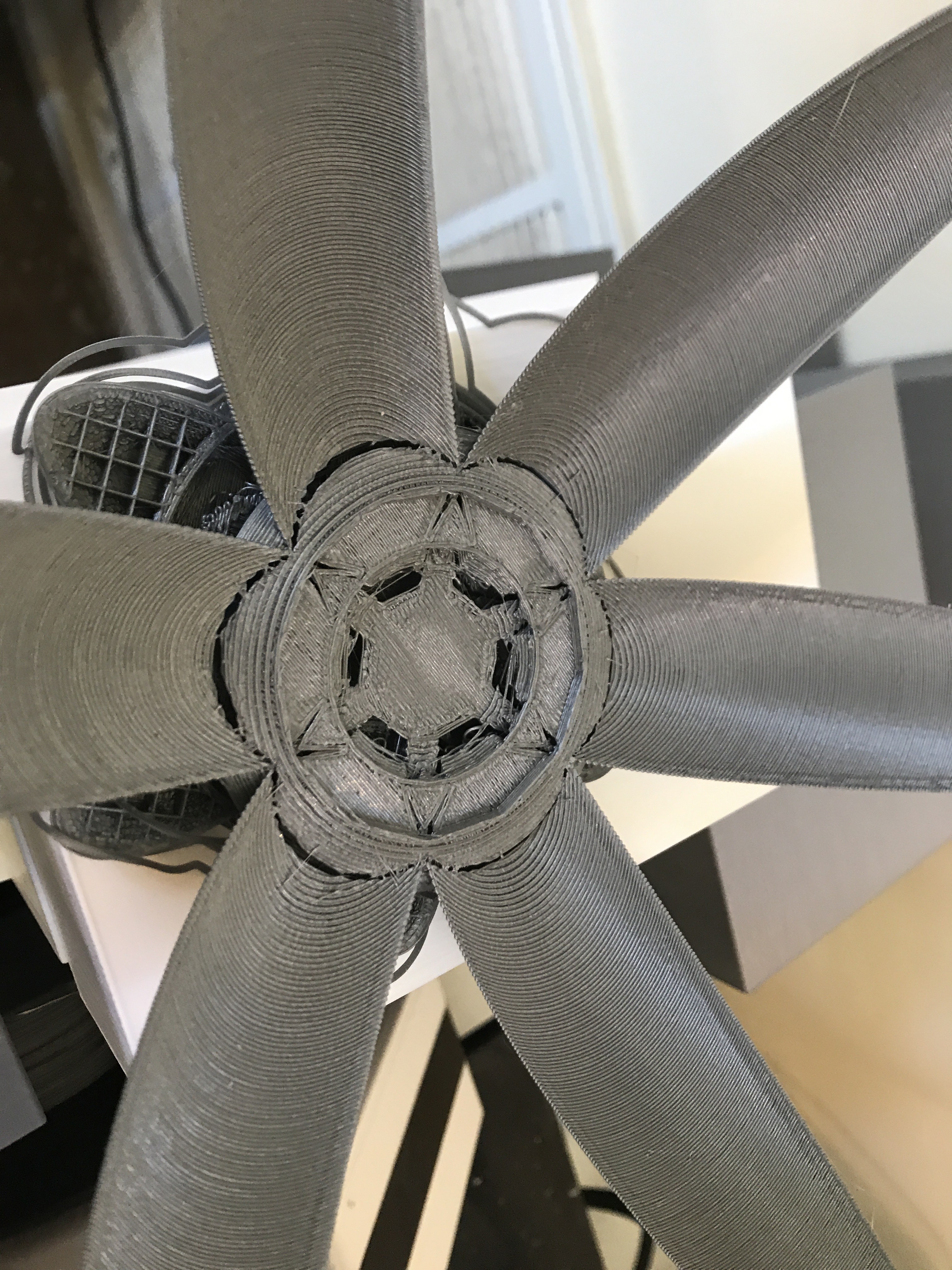
the second version of the lily was a misprint totally my fault. I moved the print head when changing filament and I should not have unlocked the stepper motors. Sigh.. anyways it did get far enough along that I could verify the center is 100 times stronger than the first version. The first version was a piece of a model I found on thingiverse but has been scrapped, the new model has three times the petals and mimicking a dish shape to reflect heat at the center collector. My fiancé even volunteered to help paint it a pretty purple like a living wild lily shown in the pictures on the page profile.
This is the new center, the heat collector will come up through the center of this and be all metal with flat black coating, there will be a silicon barrier separating the metal and plastic from touching and also a radiant barrier as well.
![]()
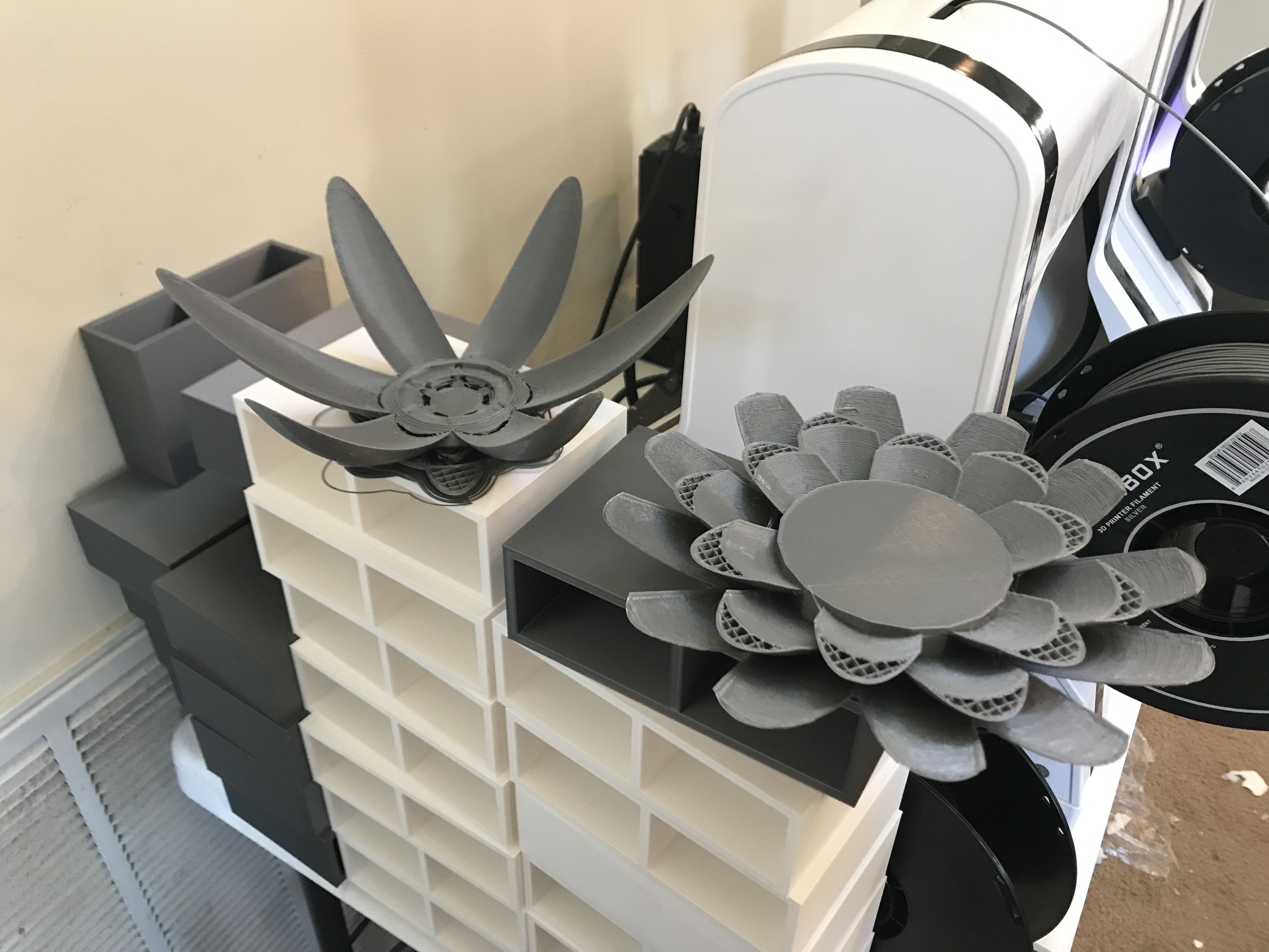
You can see in comparison to version one center and petals version two is beefy, but still looks like a flower.
![]()
-
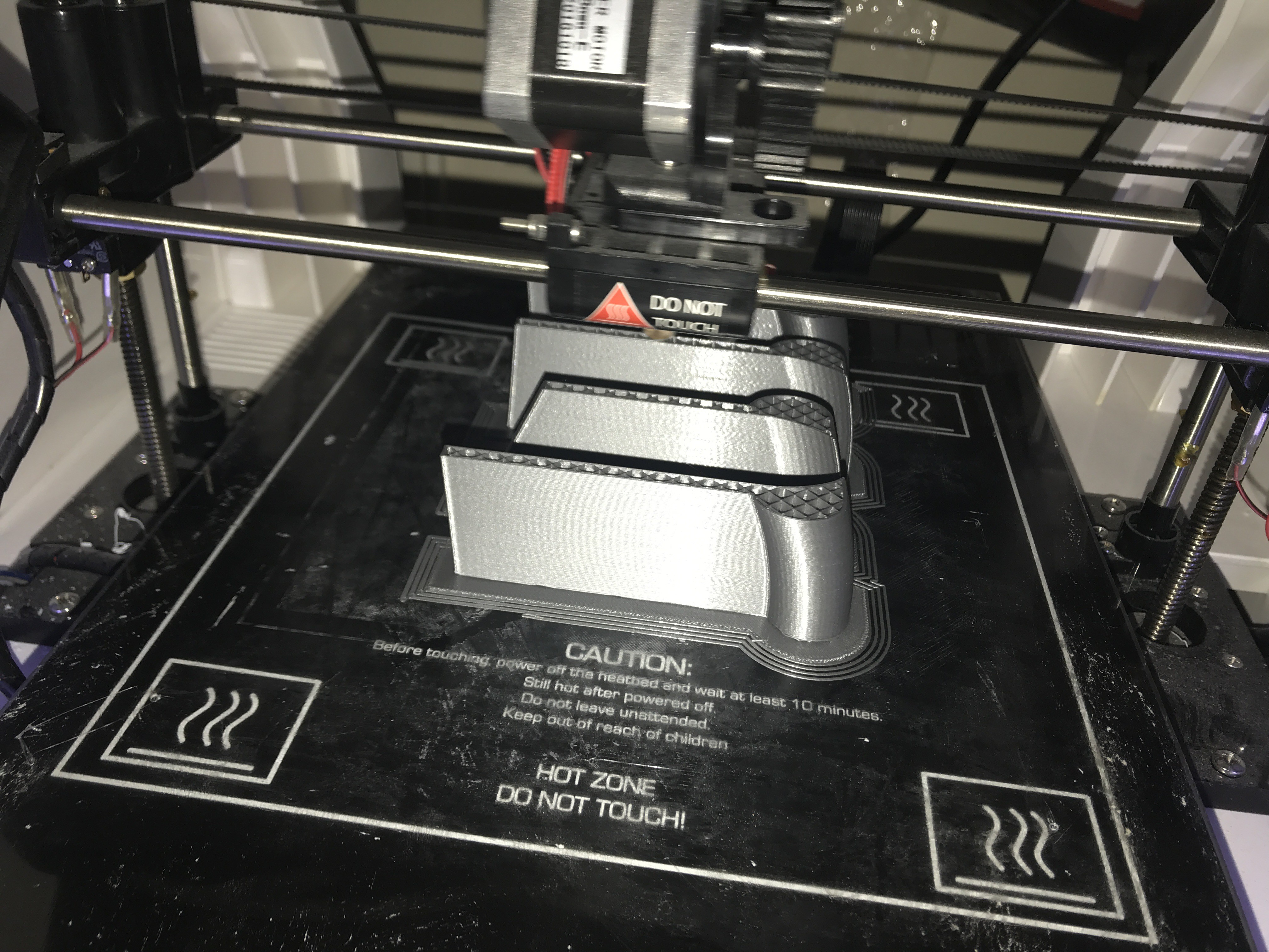
2nd version designed and printing
07/09/2018 at 05:12 • 0 comments![]()
![]()
![]()
-
1st test pieces printed
07/09/2018 at 05:01 • 0 comments![]()
ok so the lily pad needs to be bigger so I scaled it to 1.5 and started agian. I liked the section of petal reflectors, but the center was poorly designed so I made the center solid so the petals have plenty of support.
-
3D printing version 1 today
07/08/2018 at 22:44 • 0 comments![]()
![]()
in 7 hours I will have the main pieces printed. I will need to determine scale and go from there. If I like how it looks I will print at least two more sets of petals.
-
Cutting the lily model into peices
07/08/2018 at 15:36 • 0 commentsOK so first I want to say the original model I found on thingiverse. I am not using the whole model and the parts I am using will be modified so It will really not look the same in the end. I downloaded 123d to play with the parts and make what I need. I need to make a base, the petals and chop them up for printing a larger scale than I can get all in one print. I will print the first pieces tonight. I am off tomorrow to work on some of this. The petals will be lights with silver to reflect heat towards the center which will be fabricated with copper wire.
![]()
![]()
Lily Power Pods, TEG + Concentrated Solar
Thermal Electric Generator from concentrated solar, designed to float in water, small scale power anywhere in the world.

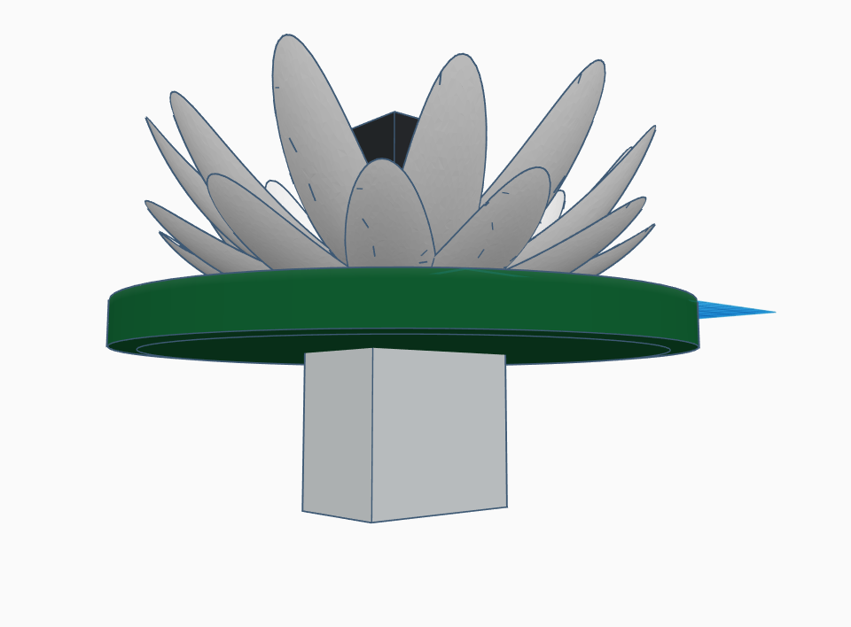
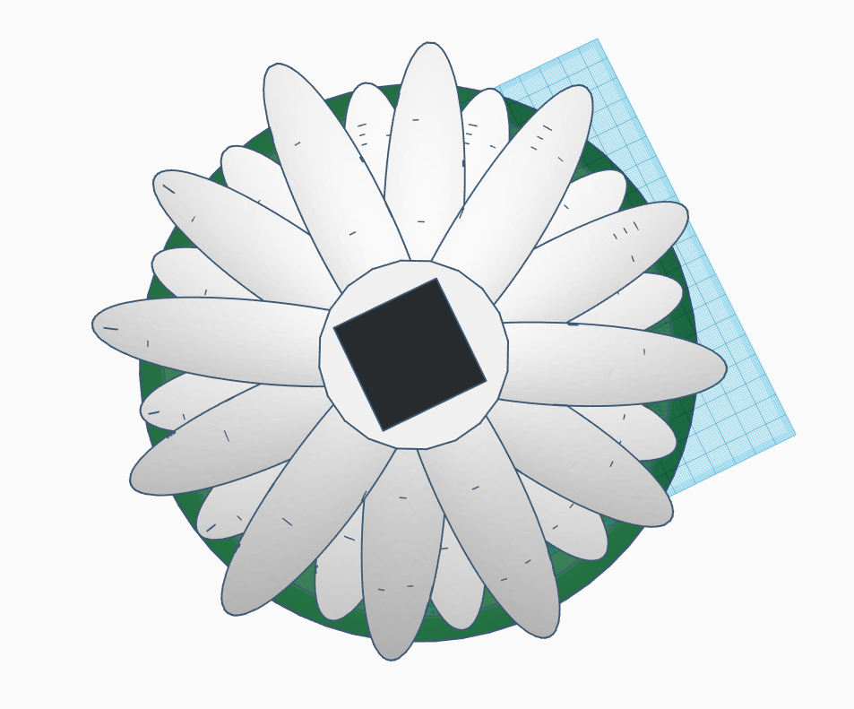
 Figure (12-1)
 Figure (12-2) a) The interstage temperature (TM12) in °K is:
 Figure (12-3) a) The lower interstage temperature (TM12) in °K is: