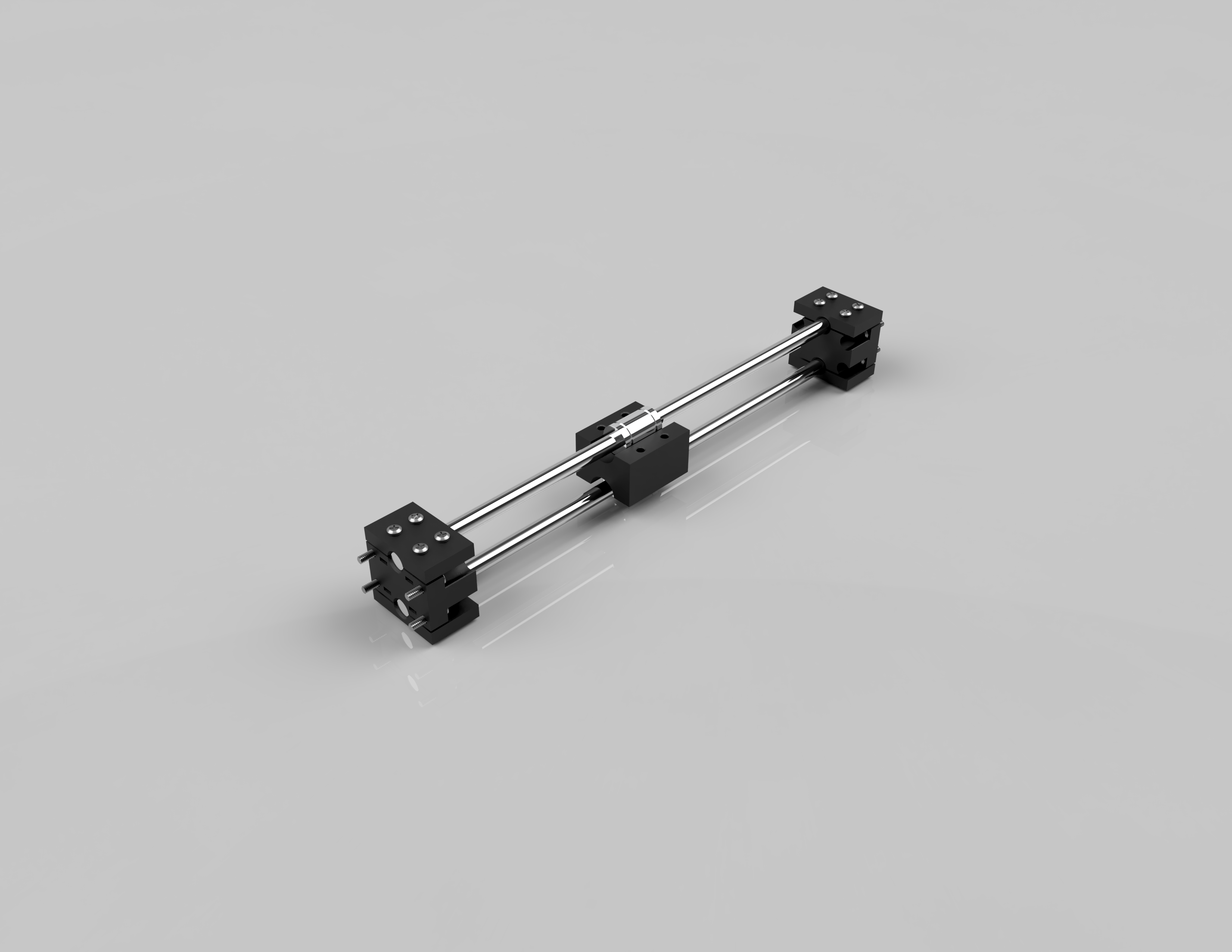
• Day 2: Design Continued

    Nicoli06/27/2018 at 17:19 0 comments

    Today's goal was to get the belt path situated and basically flesh out the full xy gantry design. Using Fusion 360 I assembled all the parts I designed so I can visualize the motion. I designed a movable motor mount so that the same design  can be used for both the top rail and the bottom rail. The benefit of core xy is that as long as the motion system is fully constrained the belt path can be a little wonky and it'll still work really well.

  • Day 1: Design

    Nicoli06/24/2018 at 07:33 0 comments

         Today's goal was to design the basic frame and work out the linear motion system on the X and Y axes. I started by utilizing the "import from McMaster-Carr" function of fusion 360 to bring in some t-slot extrusions and fastening hardware. It isn't entirely necessary to bring in all the fasteners and corner braces but I wanted to be able to model around them and leave proper tolerances. After doing all the joints and making sure things were sized properly I moved on to actual design. 

         I started by designing the rod clamps. In order to maintain modularity I had to consider the number of rods for the (what I'm calling) linear modules. I settled on 2 rods for the modules, this was to provide the rigidity needed for the x axis and also stabilize the y axis. The mounting block were designed to accommodate the 2 rods at an arbitrary spacing and use a clamp plate held on with #6/32" x 5/8" machine screws.

         Designing the bearing mount was trivial once I knew the dimensions of the LM8UU bearings I am using and the spacing of the rods. I used the same clamp plate design used for the rods to hold the bearings in place. I also incorporated a standard hole pattern to the side of the bearing mount to allow for the 3 linear modules to be assembled and to allow for the hotend to be mounted.