 Nicoli
Today's goal was to design the basic frame and work out the linear motion system on the X and Y axes. I started by utilizing the "import from McMaster-Carr" function of fusion 360 to bring in some t-slot extrusions and fastening hardware. It isn't entirely necessary to bring in all the fasteners and corner braces but I wanted to be able to model around them and leave proper tolerances. After doing all the joints and making sure things were sized properly I moved on to actual design.
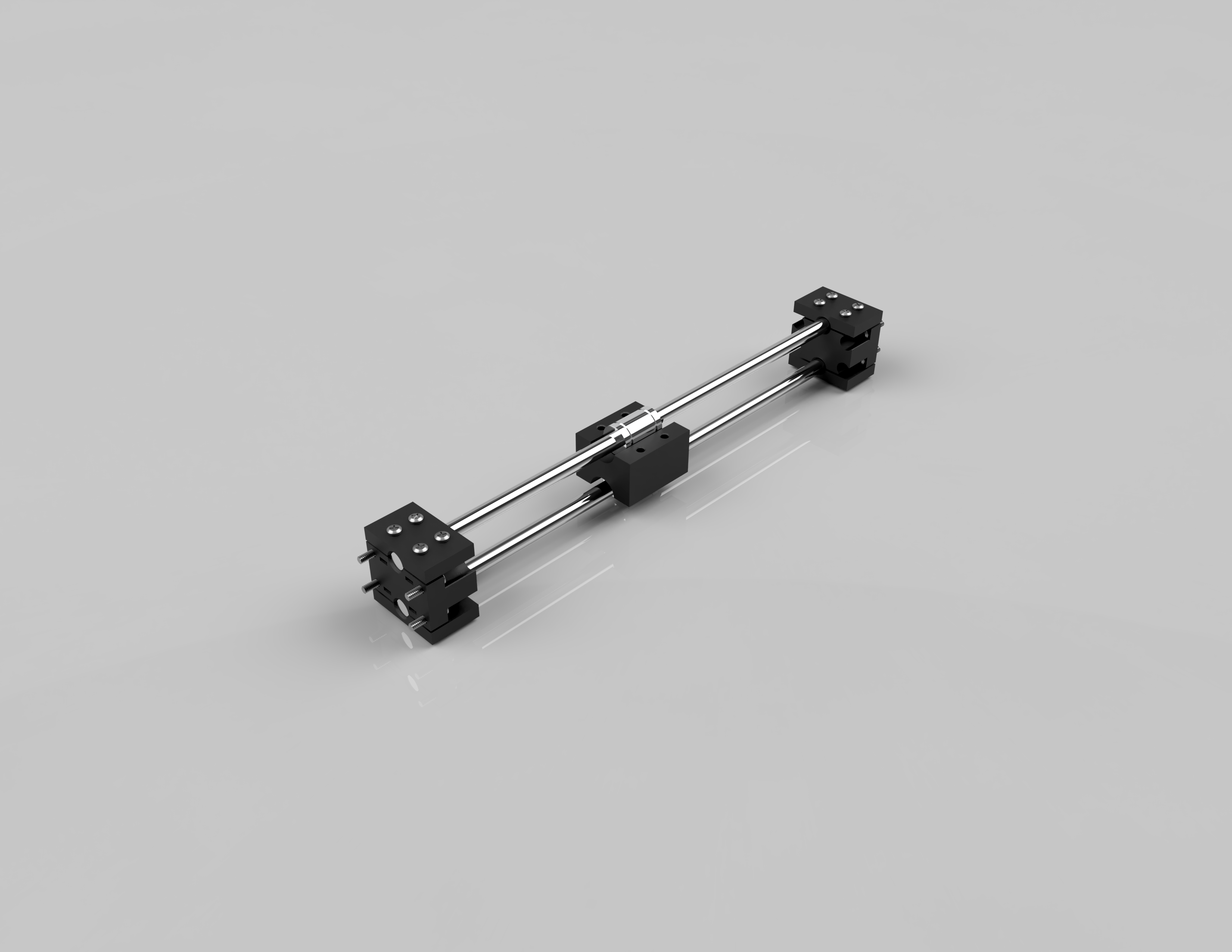
I started by designing the rod clamps. In order to maintain modularity I had to consider the number of rods for the (what I'm calling) linear modules. I settled on 2 rods for the modules, this was to provide the rigidity needed for the x axis and also stabilize the y axis. The mounting block were designed to accommodate the 2 rods at an arbitrary spacing and use a clamp plate held on with #6/32" x 5/8" machine screws.
Designing the bearing mount was trivial once I knew the dimensions of the LM8UU bearings I am using and the spacing of the rods. I used the same clamp plate design used for the rods to hold the bearings in place. I also incorporated a standard hole pattern to the side of the bearing mount to allow for the 3 linear modules to be assembled and to allow for the hotend to be mounted.
Discussions
Become a Hackaday.io Member
Create an account to leave a comment. Already have an account? Log In.