 mmca
mmcaIn our first Blinky Ball all 16 slices where the same PCB. You would build out the main slice with MCU, Bluetooth, battery charger and the other slices just got LEDs and a driver chip. I was super happy with this and was constantly patting myself on the back about it.
But as we moved to the RGB ball and especially when we got to the battery powered RGB ball all the slices started to get specialized.
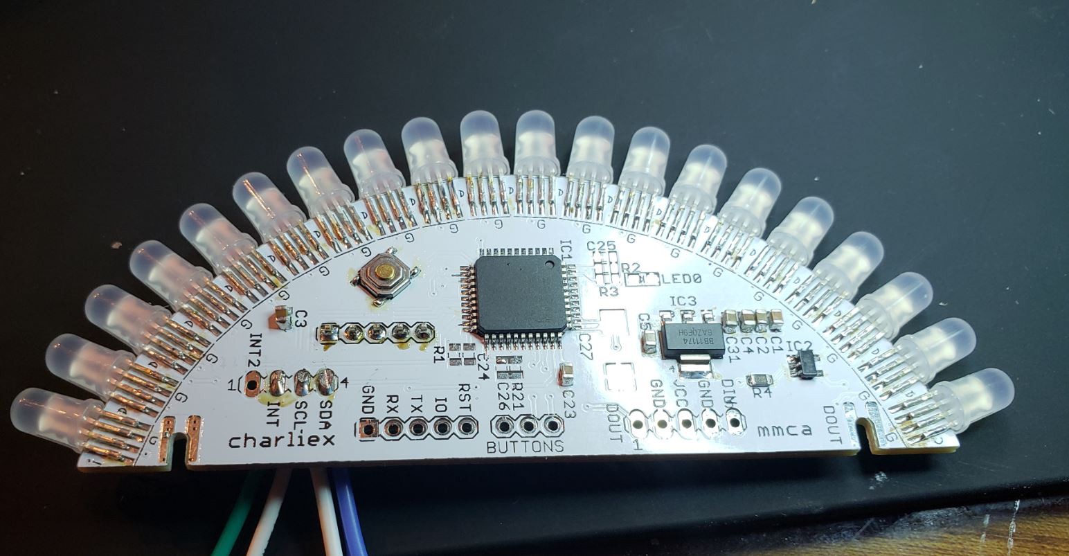
This is the driver slice with Cypress PSOC4 and an logic level shift (the PSOC is a 3v3 device and the LEDs expect 5v signal). In this version all the colors/patterns are done in PSOC4. In the next version the heaving lifting will be offloaded to another processor.
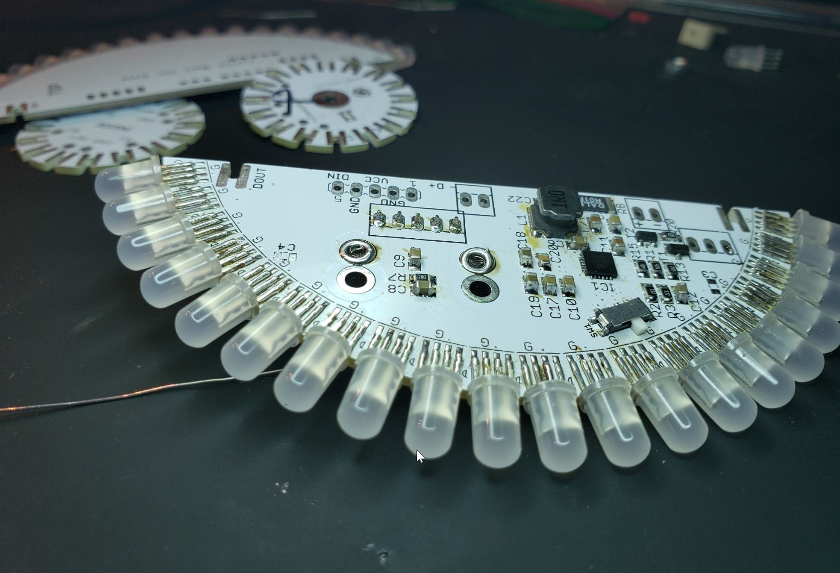
This is the power slice, It takes USB power and charges the 18650 and boosts the 3.7v of the battery up to 5v. We are using the IP5209, a highly integrated power management SoC, it isn't the best documented chip, but we are figuring out all its little oddities. It is a great little chip, you add a couple caps, resistors and an inductor... good to go. Unfortunately there is no easy way to disconnect the 5V from the circuit, so the next revision has bits for that.
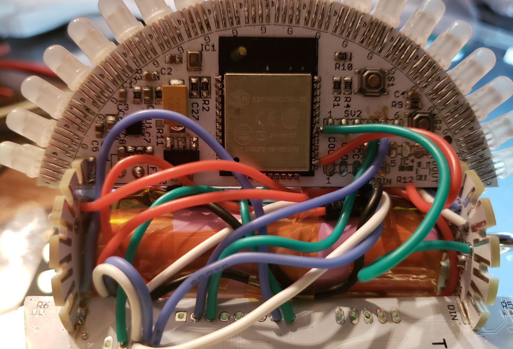
Behind that mess of wires is the ESP32 slice. We had the ESP8266 for some of the early protos but after using the EPS32 on the 2018 L1 badge, it made sense to switch. This slice also has an i2s microphone and DAC.
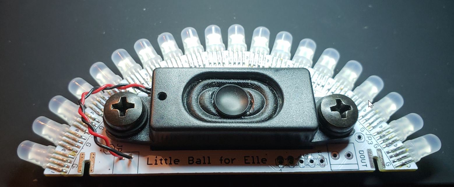
And here is the speaker slice. That is a little speaker from a Lenovo monitor, they are available oinline from a factory buy out.
What we wanted to do for the third revision was bring all the parts together back on to one slice. Bringing it back to the original vision.
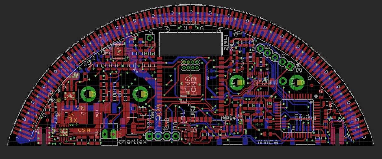
This is what the main slice looks like now... ESP32, LED driver, mic, DAC and all the power bits. It is off at manufacturing now, fingers crossed.
Discussions
Become a Hackaday.io Member
Create an account to leave a comment. Already have an account? Log In.