 Johannes
For the second version of scanner-board I did a spice simulation.
(I should have done this before building the first prototype.)
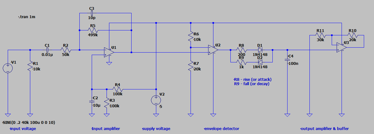
The circuit has three parts:
- first the input stage with input amplifier because of the small signal from the US sensor,
- second a comparator / envelope detector for creating a lower-frequency signal and
- third output amplifier.
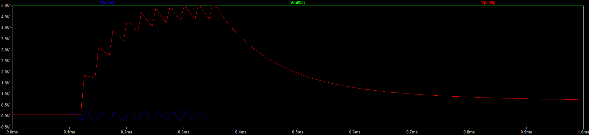
The signals: input voltage (blue) and output voltage (red)
I've read this document from TI (pdf warning) which gave me some hints for the input stage.
Virtual GND for U1 is created by R3 and R4. This is necessary because I use all opamps in single-supply.
The envelope detector acts like a comparator paired with a lowpass filter. Because there is no feedback-loop U2 outputs only 0V or 5V. C4 together with resistors R8 and R9 set rise and fall time. A simple lowpass filter wouldn't do the trick since I'm interested in the peaks of the signal.
Next step will be building this circuit and testing. I'll install potentiometers for R6/R7 R8, R9 and R10/R11 to adjust the values during live-tests. Probably there will be a lot of adjusting before everything is good.
I'm excited since signal acquisition and first tests of 2D images are getting close!
A little update:
Here is the image of the signal after the preamp:
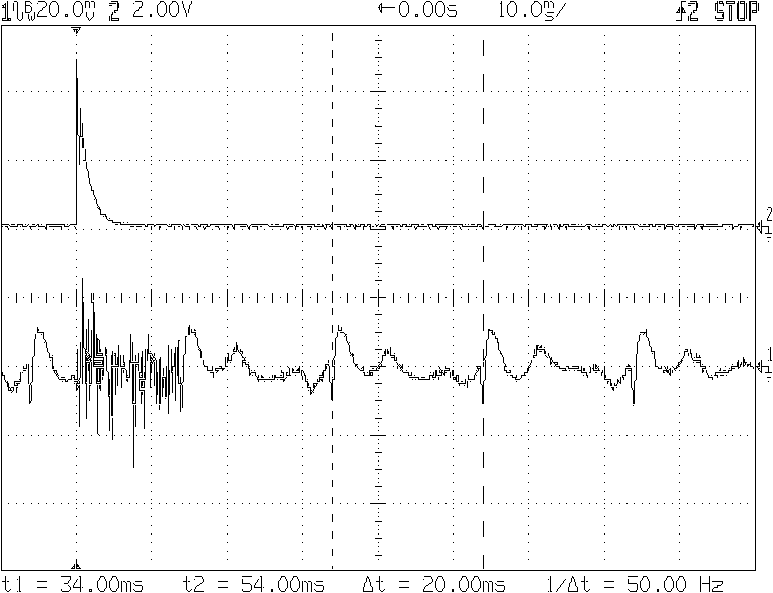 Soo, I need to eliminate all low frequencies below 50Hz.
There will be another update when I created the highpass filter and the signal is clean.
Something else I think about: ~15ms may be too long for the burst.
Soundwaves travel at approx. 300m/s.
While sender is active, the receiver may also pick up the outgoing burst and this results in a 'dead-zone' of ~2.25 meters. (300m/s*0.015s = 4.5m).
With a burst length of 3ms this dead-zone can be reduced to 0.5m.
In other news: I managed to capture an image from an old HP oscilloscope via serial port.
No more need for low quality screenshot-photos :)
Discussions
Become a Hackaday.io Member
Create an account to leave a comment. Already have an account? Log In.