 Johannes
I had some time since my last log and a lot of thoughts about the current setup.
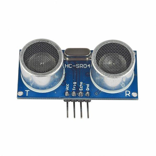
One thing I thought about is lobes of the sensors. There is a HC-SR04 datasheet here, where this image can be found:

I guess, I will need a much broader directivity, at least for the sender.
Second thought: signal strenght.
Maybe a more powerful sender can enhance signal strenght on the receiver part.
This leads to the topic, I'll cover next: different sensor types.
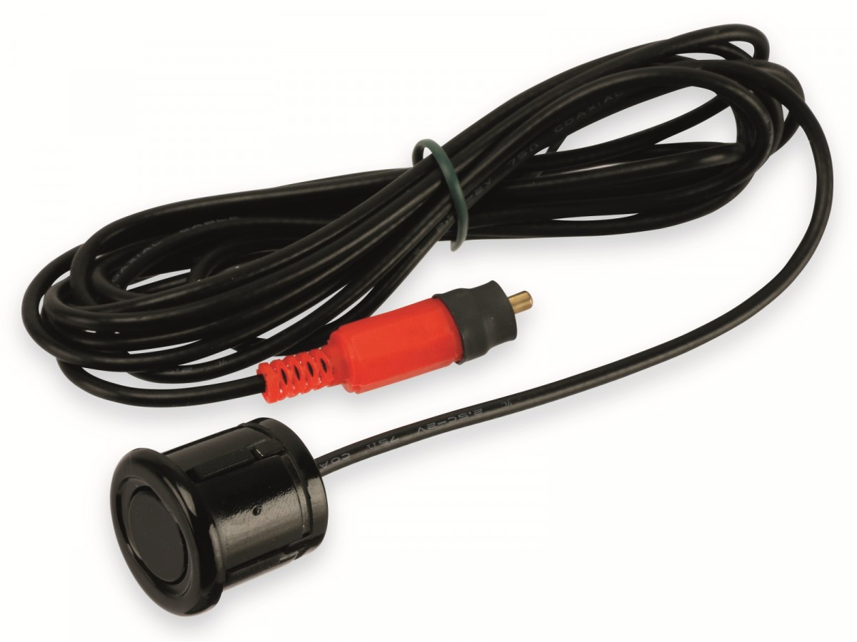
I found some random sensors on e*ay.
First, I'll take measurements about their directivity and power then I'll make changes to my test rig.
After all I do want to believe that this project will succeed.
 |
|
 |
####
Edit1:
To measure directivity I created a small test-rig.
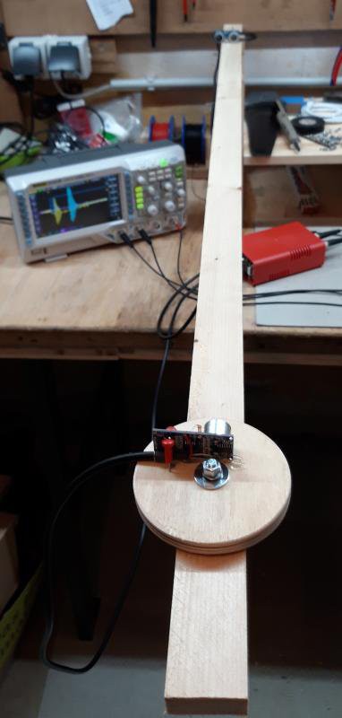
There is a sender-element at the end of the rail, connected to my red box. The rail has a wheel attached that can be rotated.
I guessed that eccentric mount does not affect the measurement a lot, so I mounted the sensors a little bit of centre, because it was easier this way.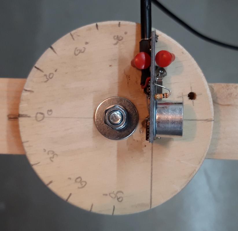
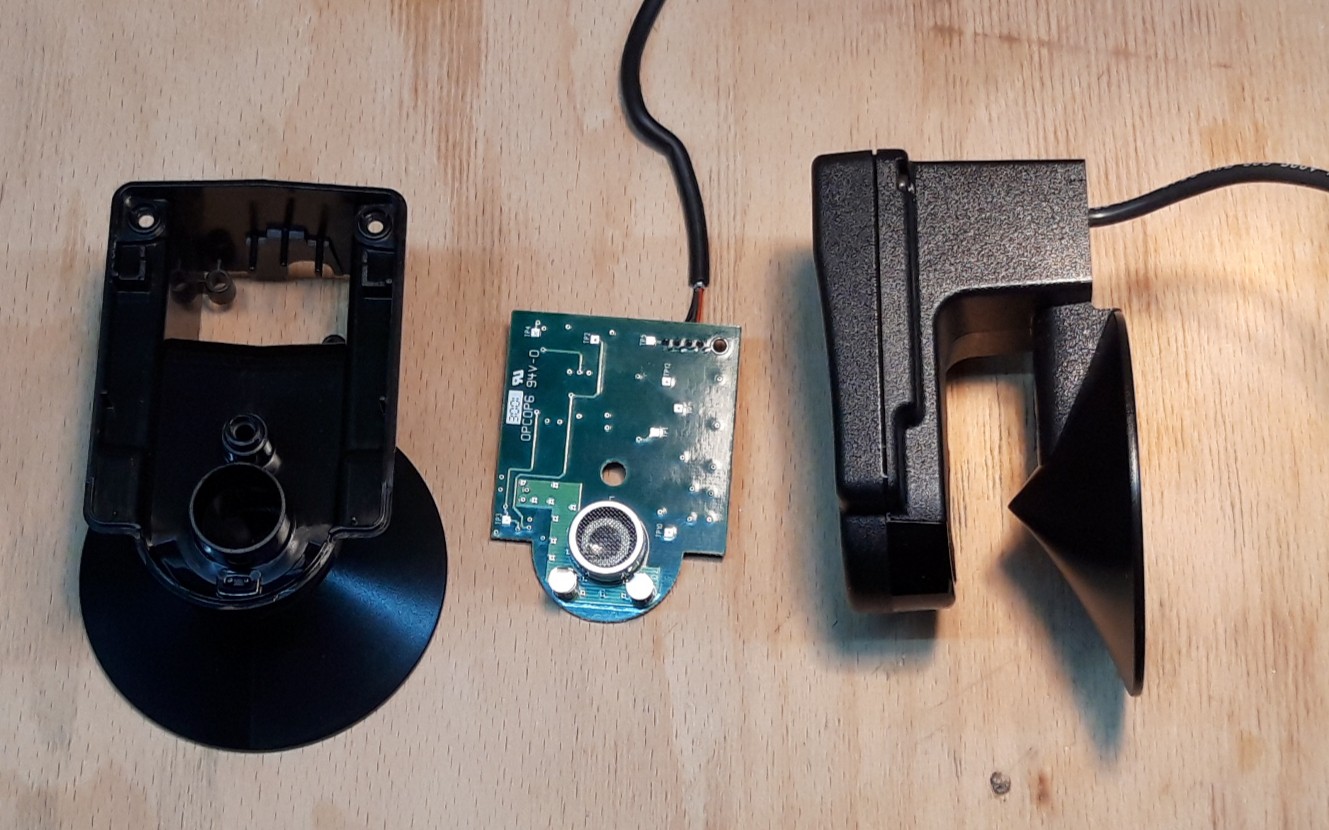
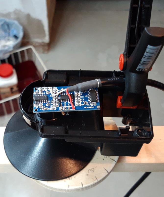 Likewise with "the cone". Here my HC-SR04 Sensor mounted inside the plastic case.
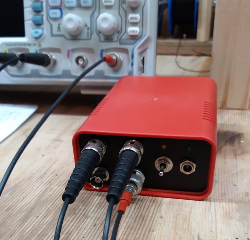
I did modify the red box a little bit, so it can be connected to my scope.
So after all was set up, I took measurements of signal strength over several angles.
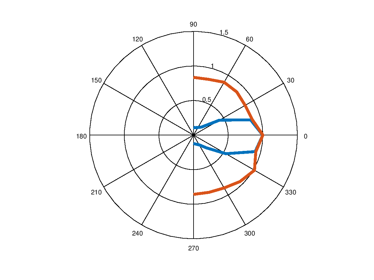
Blue is directivity of HC-SR04 and red of 'the cone'.
I'm very happy that I somewhat could reproduce the diagram from the HC-SR04 datasheet.
Earlier I did mention another sensor K-14WP10, this sensor will need a preamp which I didn't want to build right now. Therefore I just compared the two.
Just as said before, broad directivity is important for me, so next time I'll use 'the cone' for taking measurements.
####
Edit2:
In the diagram above each sensor directivity is normalized against its amplitude at zero degrees.
For 'the cone' aplitude at 0° is lower than the amplitude of HC-SR04.
Discussions
Become a Hackaday.io Member
Create an account to leave a comment. Already have an account? Log In.