 Mike Szczys
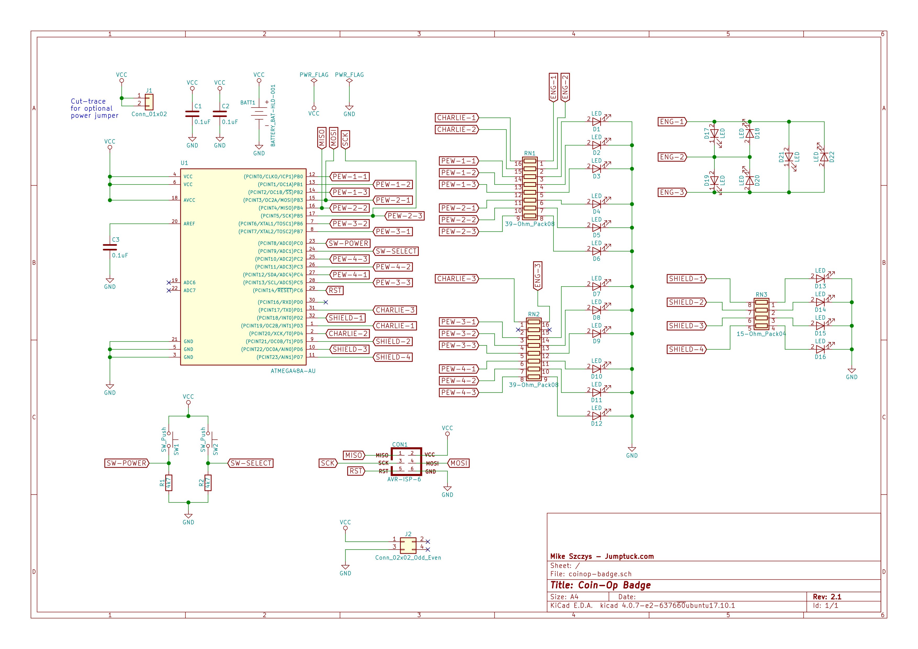
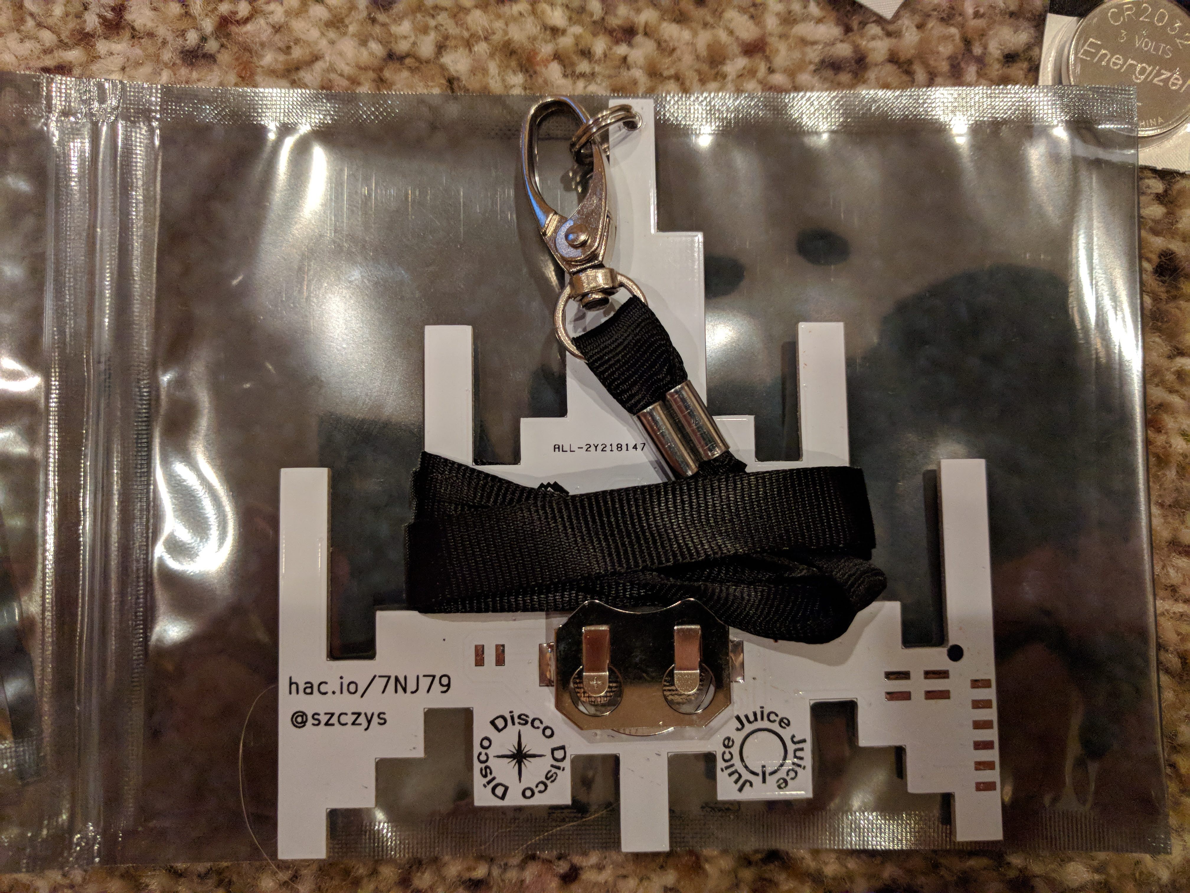
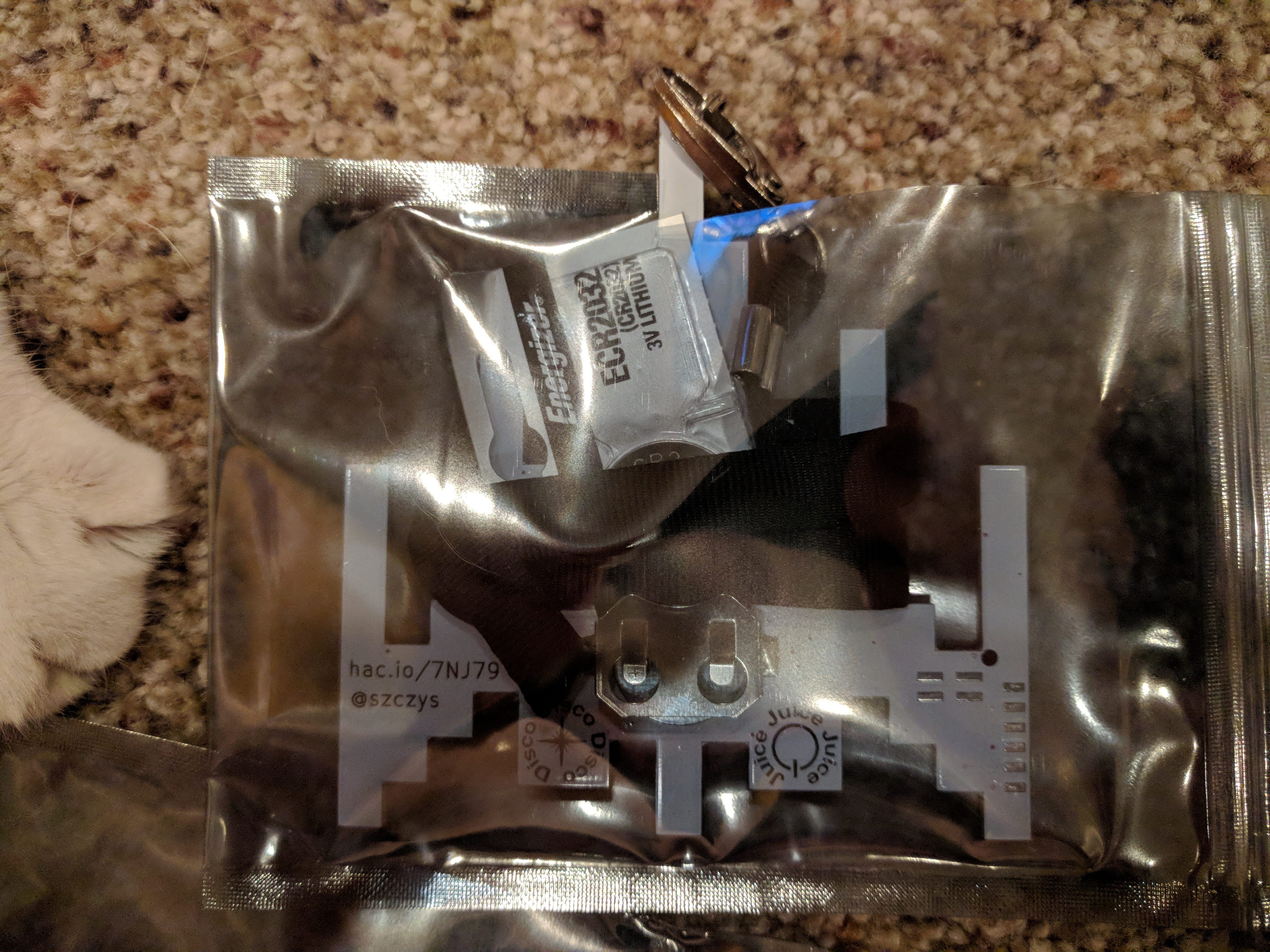
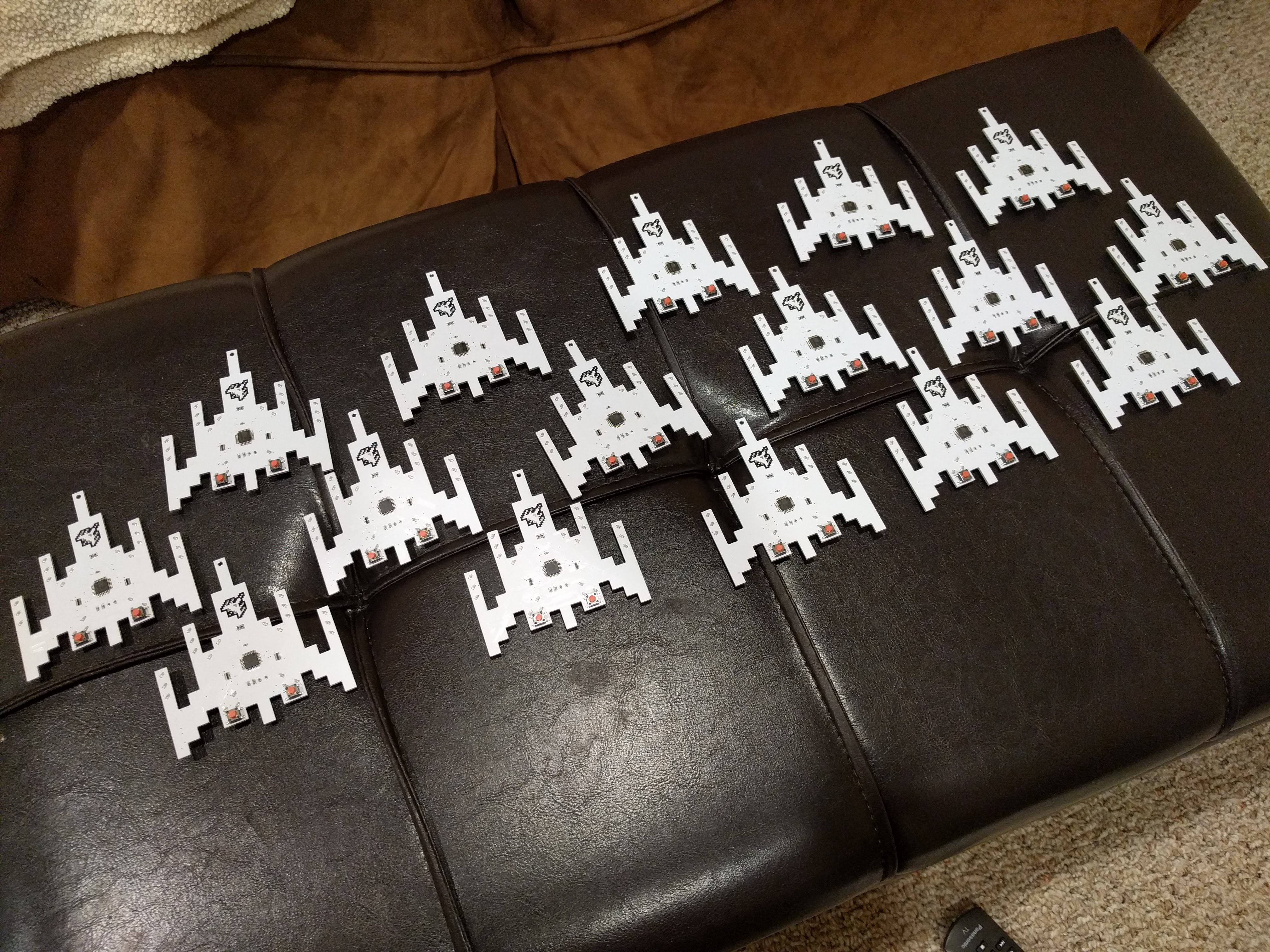
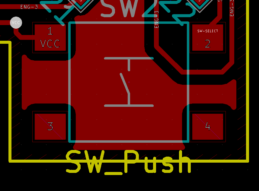
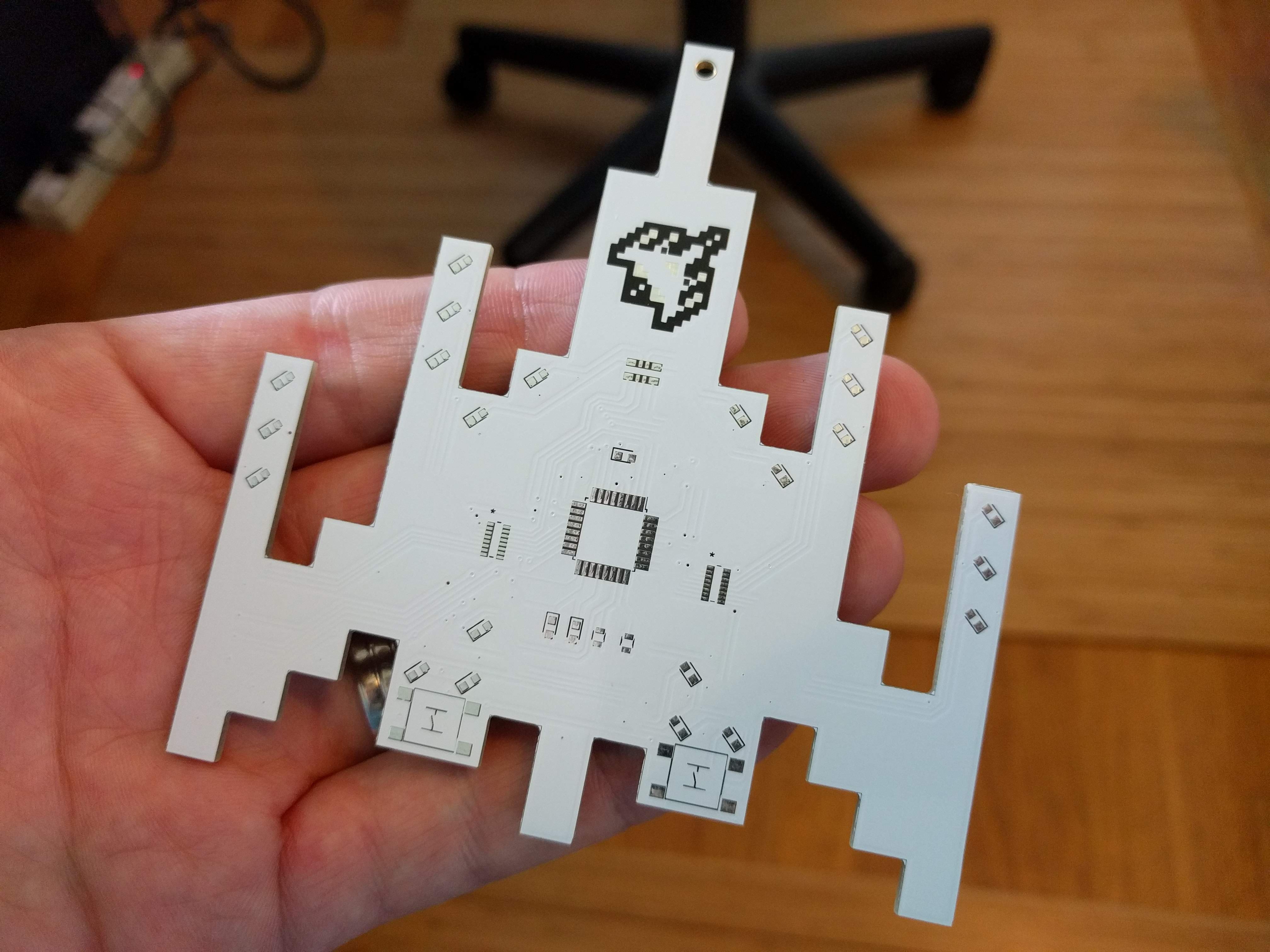
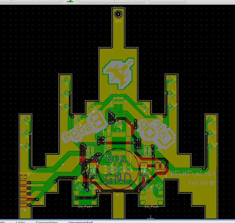
The major components of this badge include an ATmega48 microcontroller that drives 18 red LEDs, 4 blue LEDs, takes input from 2 momentary push buttons, and is powered by a CR2032 coin cell.
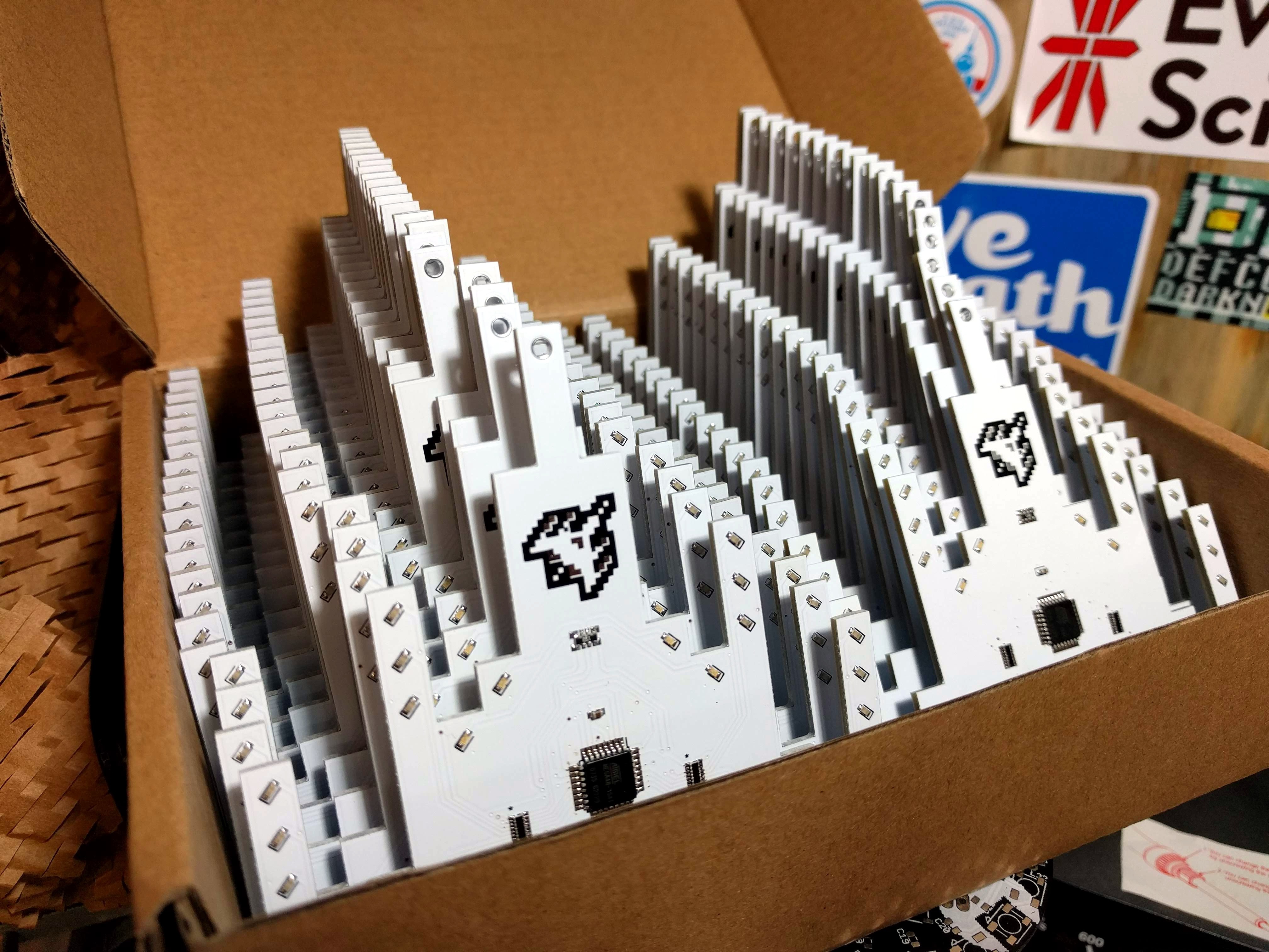
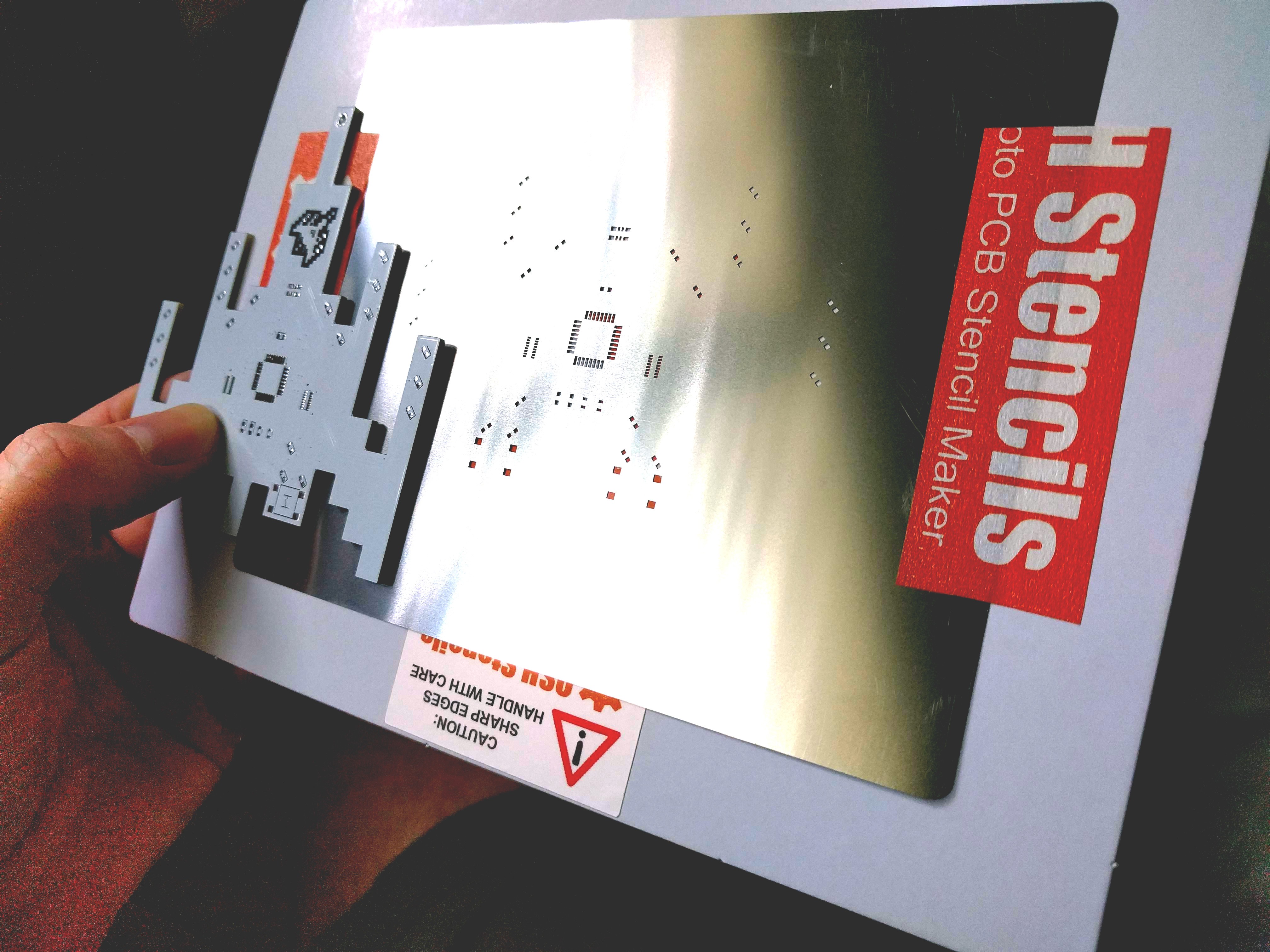
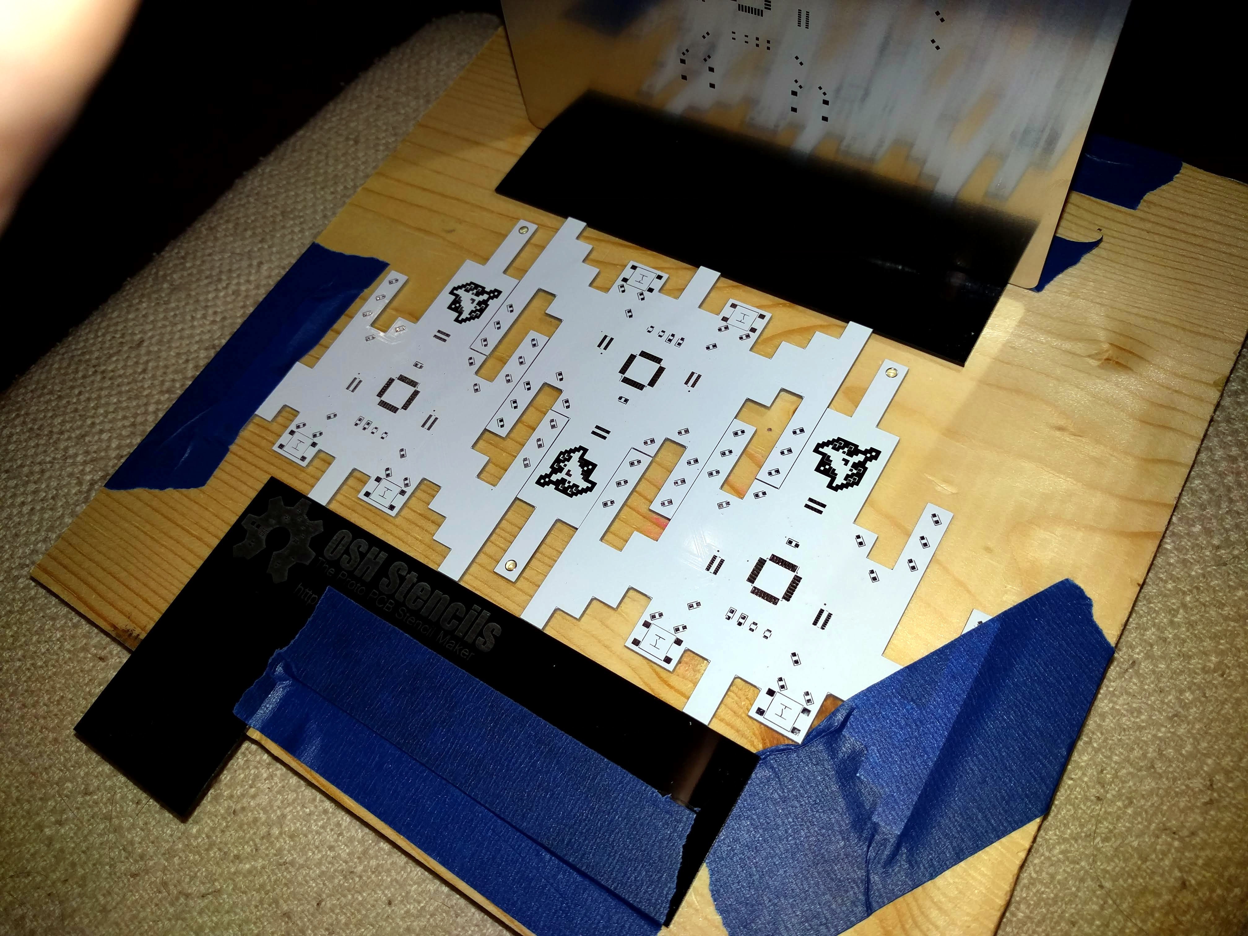
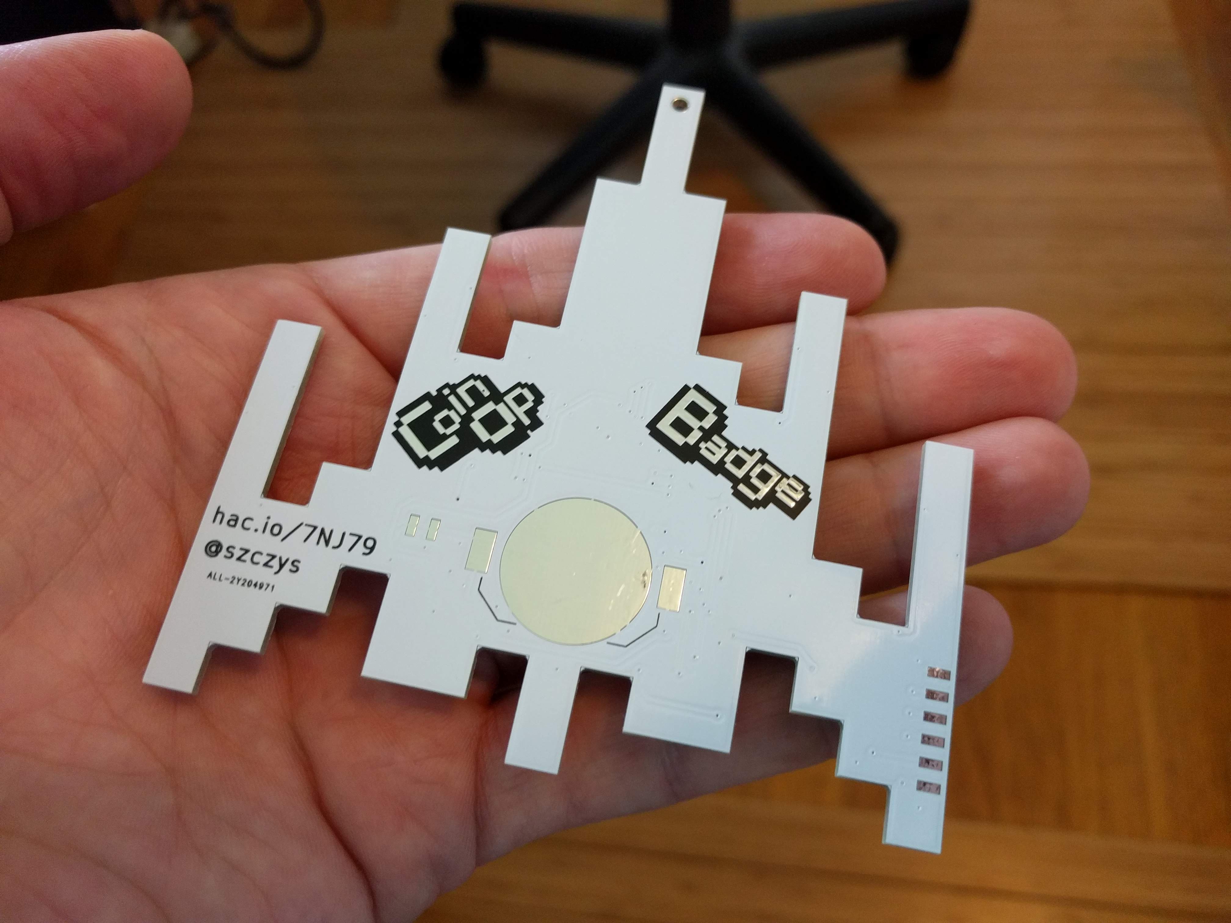
I wanted a fast-paced project that let me do everything, from concept to assembly, and this is it. I just received a toaster oven to do the reflow (previously I had been using a hot air rework station). I built a programming jig using pogo pins. I ordered a solder stencil for the project and did two PCB runs, receiving a total of 59 boards.
Here's a brief demo of the functionality:
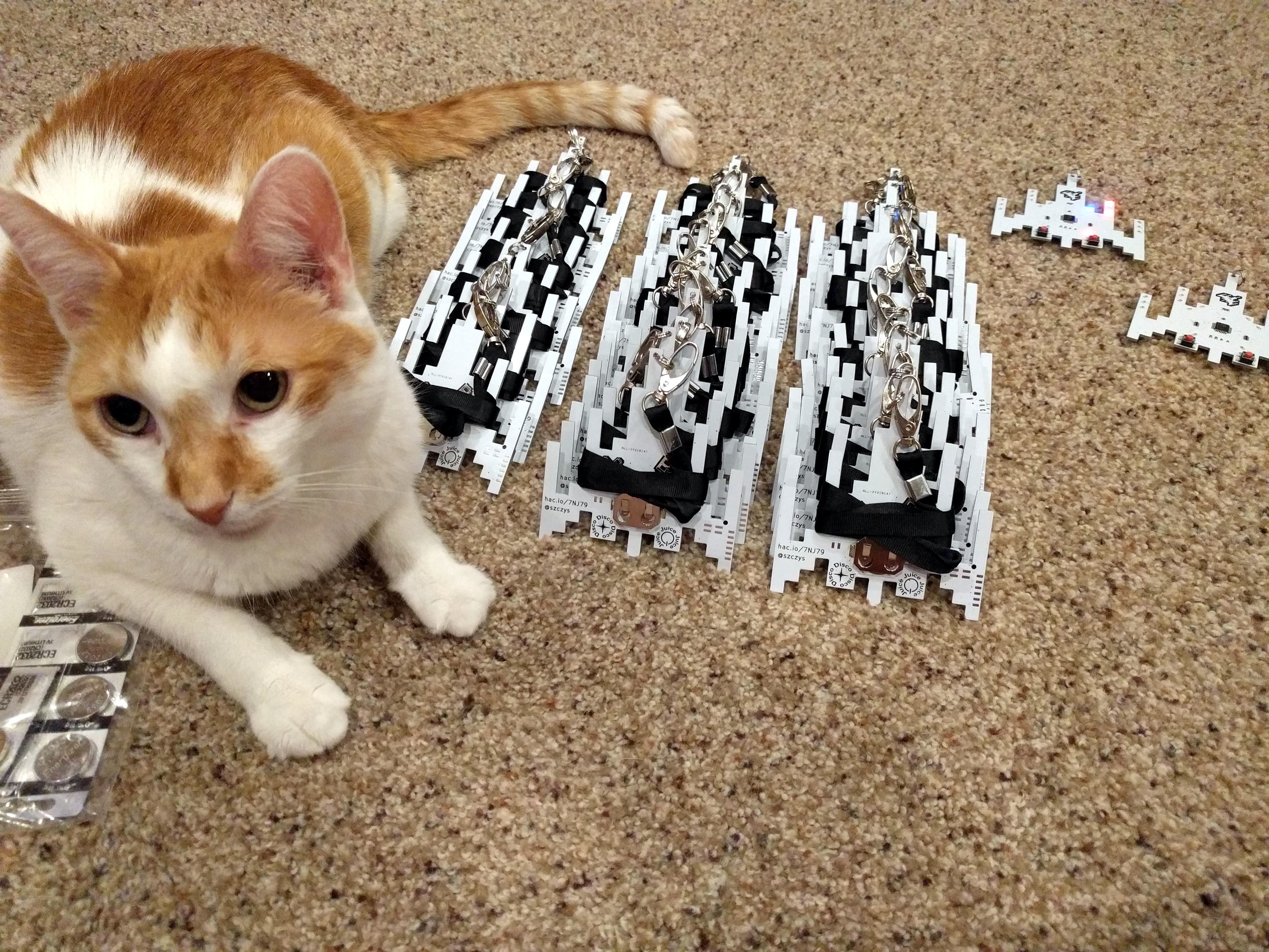
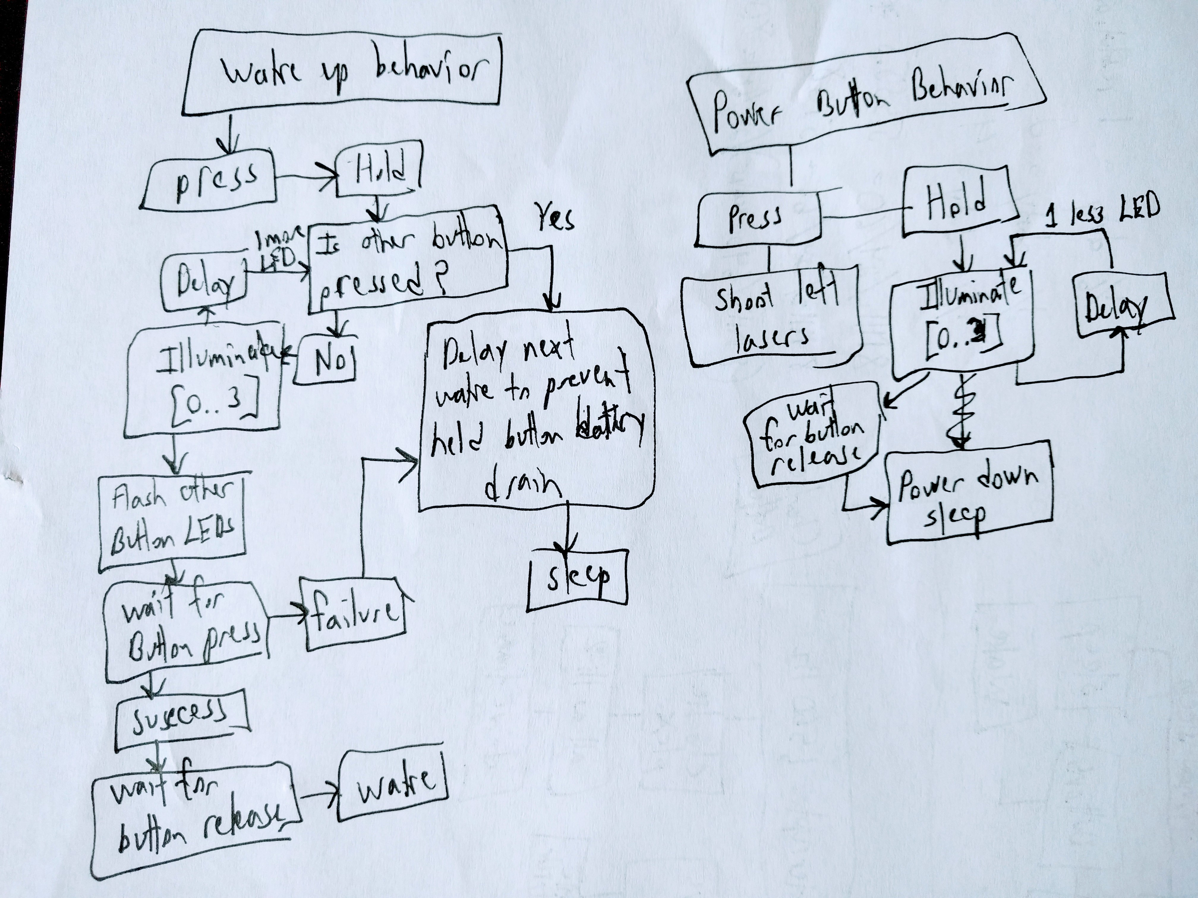
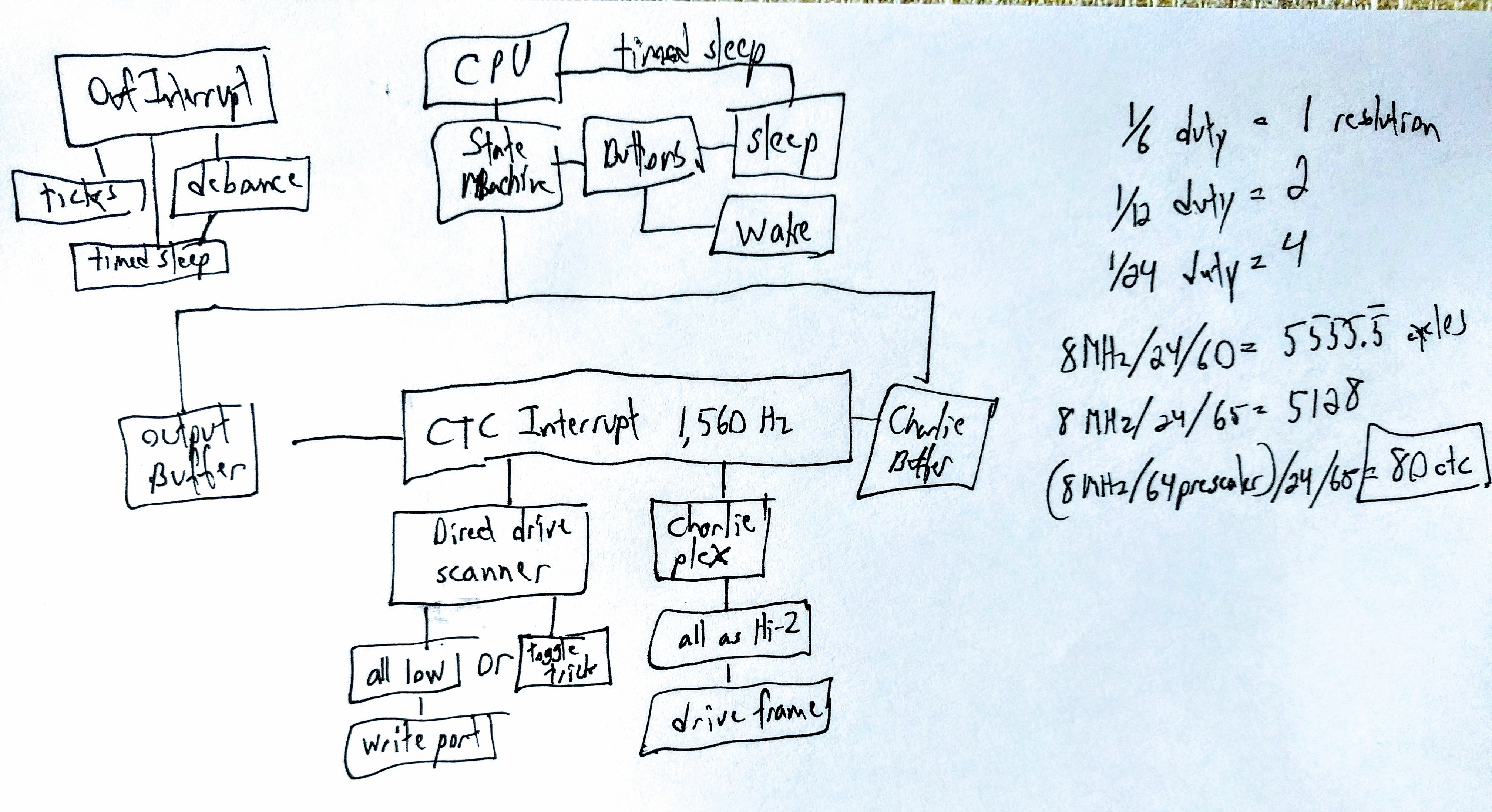
The badge sleeps for 4 seconds between each visualization, consuming just 4.3 uA. Short button presses on the left and right buttons fires the lasers on that side of the badge. Holding the right button scrolls between visualizations. Holding the left button powers the badge on or off. When in the off mode the power draw is 0.1 uA.
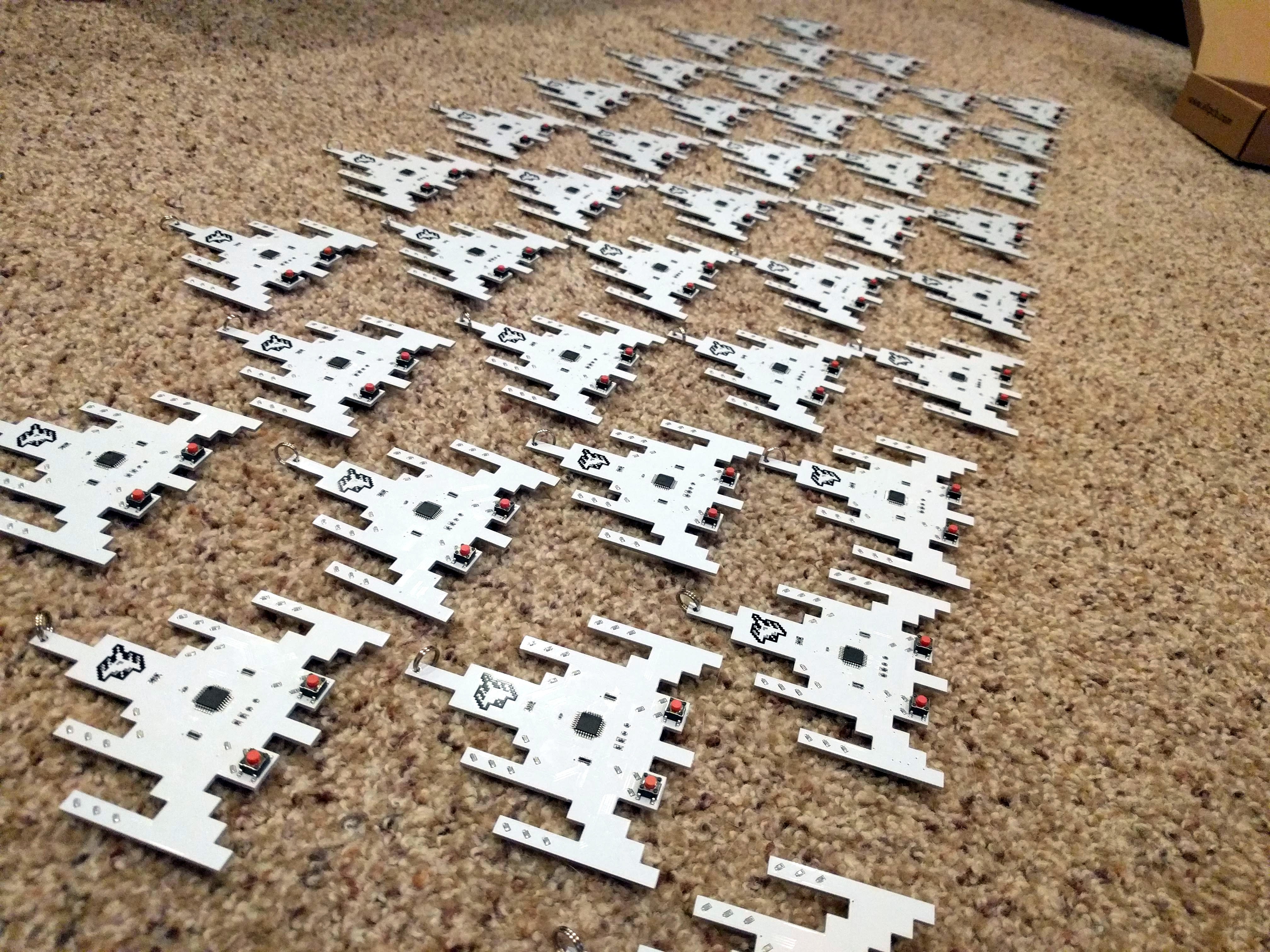
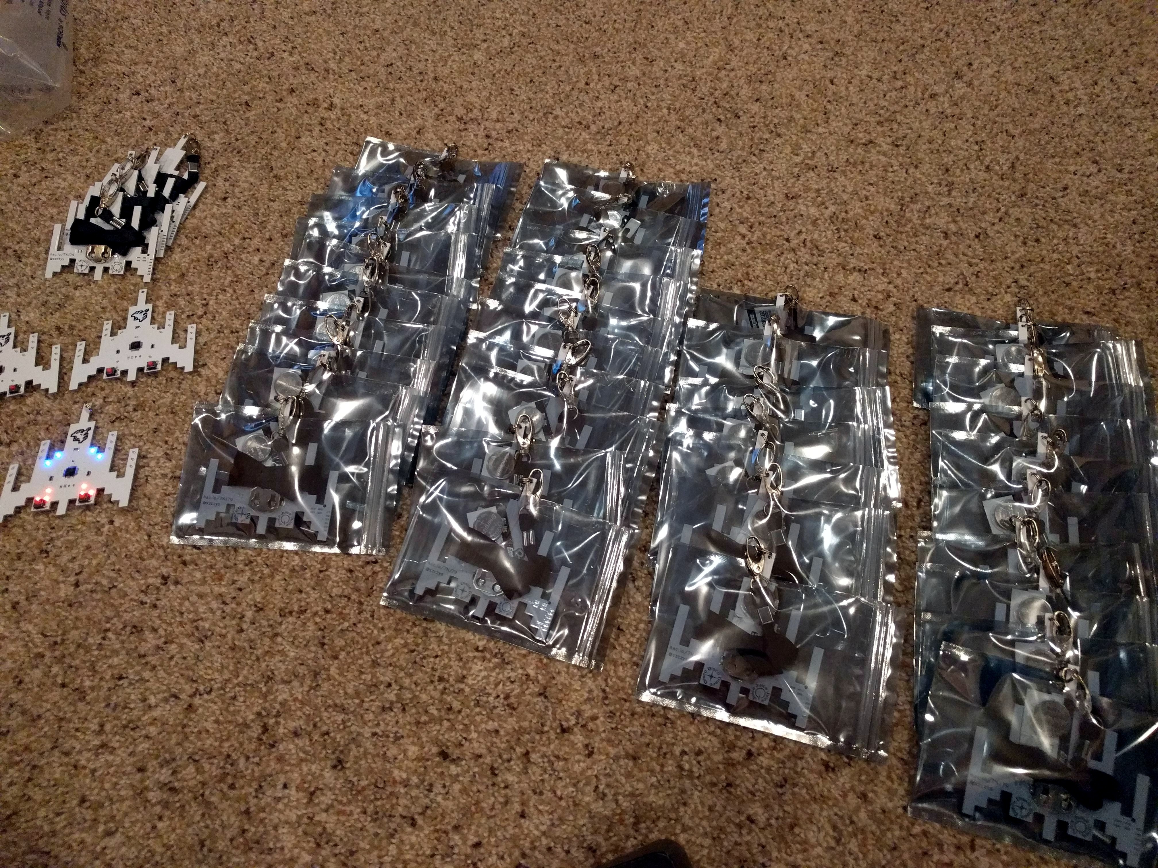
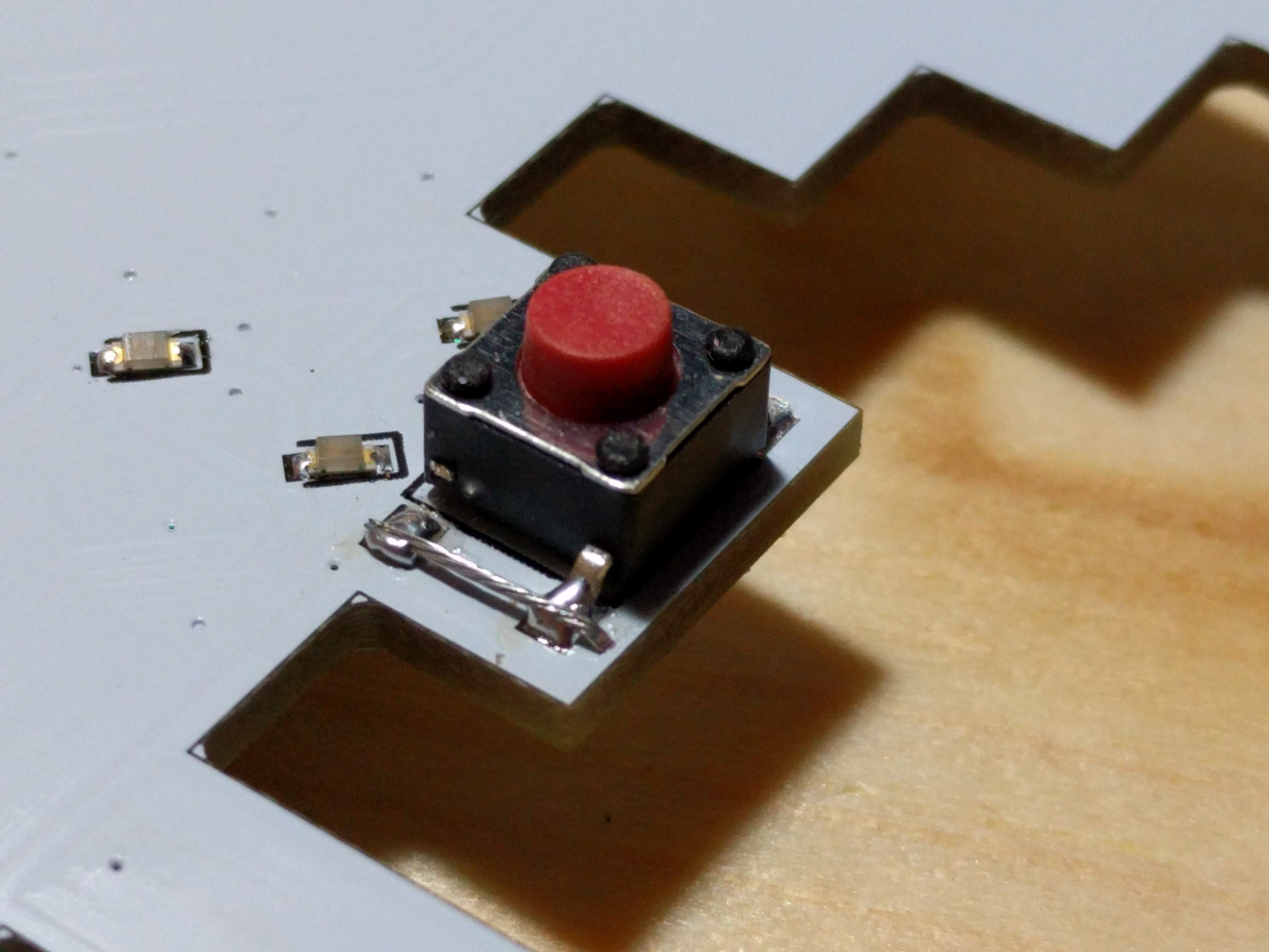
Assembled by hand in my basement, I was able to do 4 boards in about 90 minutes. Populating all of the components wasn't that bad, but because of the fine-pitch on two of the resistor networks I had to hand rework every badge (openings in the solder stencil needed to be smaller).
Check out the time lapse video I made of the final four badges:
Current Status:
I have reached v2.1 and fully assembled and packed 59 badges. The firmware is currently using 4080 bytes out of a total of 4096 available.
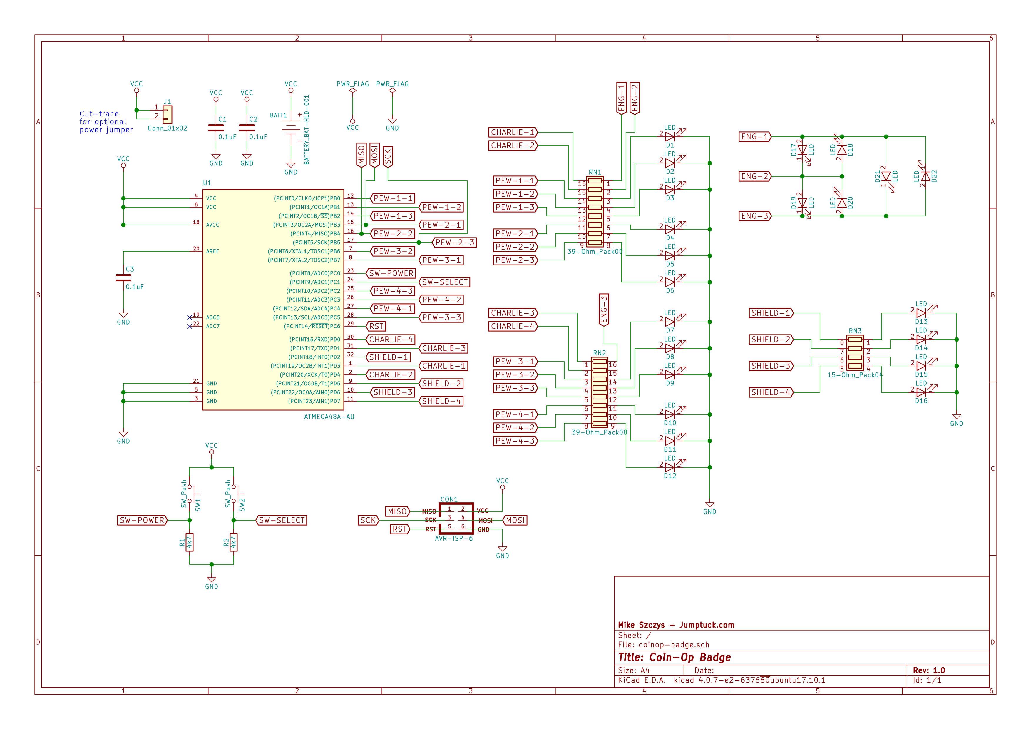
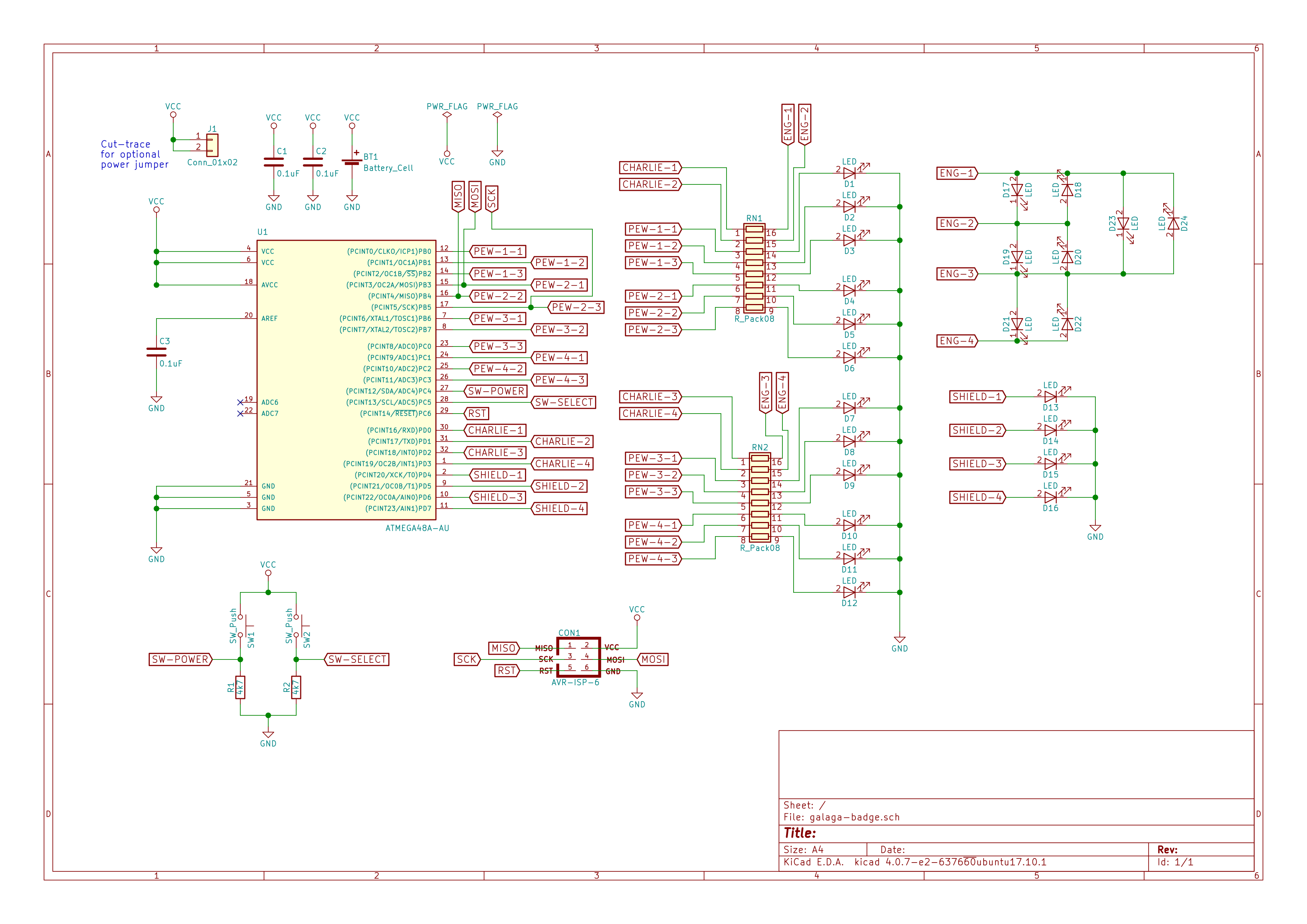
Here's a PNG of the current schematic:

 Benchoff
 blinkingthing
 facelessloser
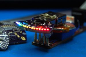
 zakqwy
did you have extras from defcon that you are intending to list on tindie ???? inquiring minds want to know if i should just get these boards made :)