 Javier Betancor
It is time to upgrade the current setup with a smart lighting system!! The aim here is to use one of the batteries to power up a headlight and a rear light. One of the three Light Dependant Resistors (LDRs) will be used to sense the environment. The other two will be used in order to decrease the light intensity when another car/bike is coming from the opposite direction. Another functionality could be that the front and rear lights will start blinking to make sure that the car spots the bike.
On the other hand, I would like to outline the usage of programmables LEDs. You can literally program anything! And I have some ideas in mind...I will keep you updated.
Please find below the list of components needed for this stage:
- 1 x 10x10 RGB LED Matrix (WS2812B)
- 3 x Light Dependant Resistor (LDR)
- 1 x 3D-printed Front Light assembly
- 1 x 3D-printed Rear Light assembly
- 5 x M3 screws + nuts for the headlight and rear light
- 3 x JSP 2.54mm XPH-3 housing (male + female + inserts)
- Different sizes of heatshrink
- Hot glue gun
- Soldering iron + soldering material
- Patience and be willing to improve your soldering skills!
First of all, I would like to show you the schematics of this stage. As I mentioned before, my aim is to show you how I am building this system, not to teach you how schematics should be represented.
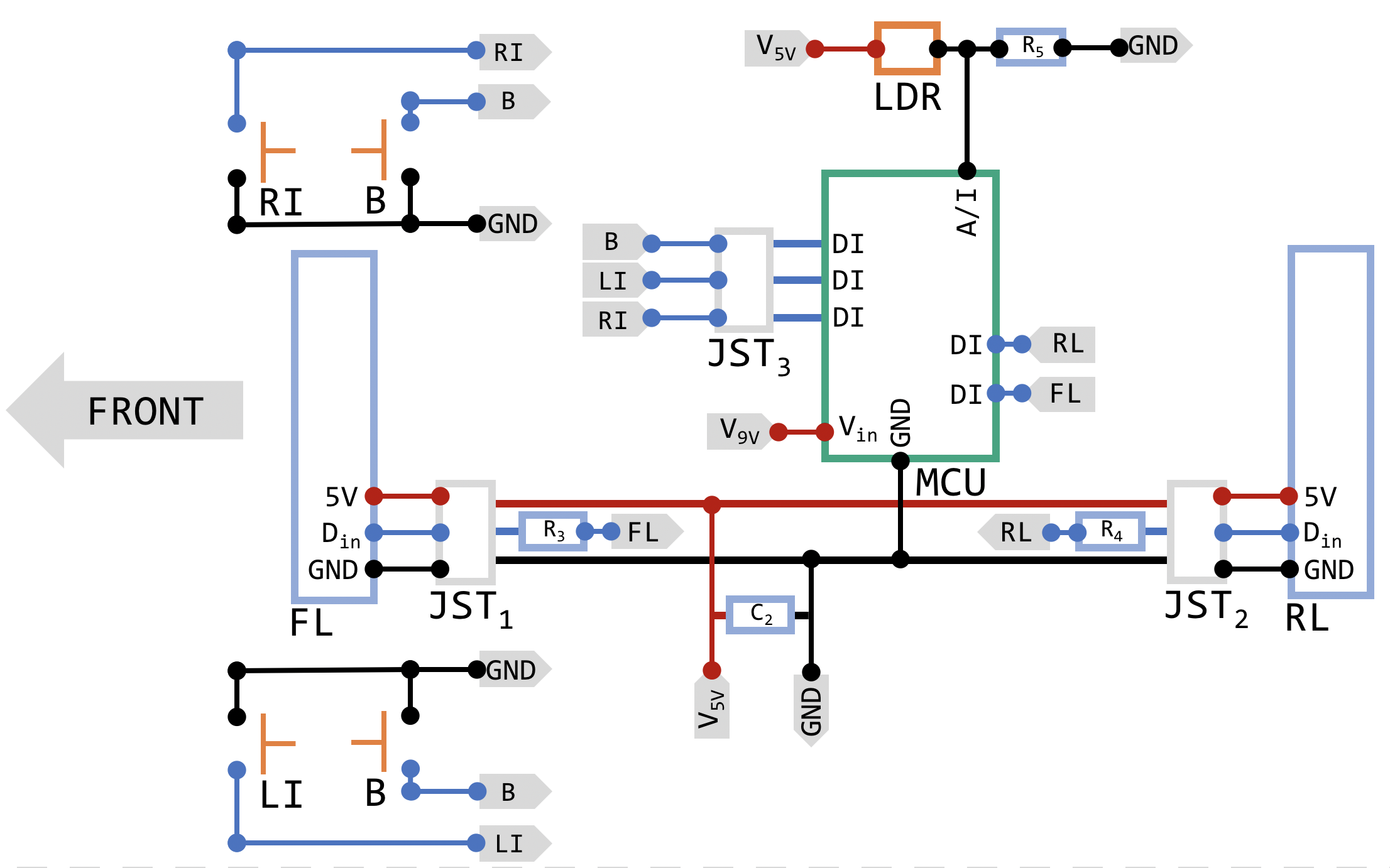
Having said that, I want you to imagine that you are currently on the bike. Now, I guess the arrow labeled as 'FRONT' makes sense. I know I mentioned 3 LDRs and I am showing only one as I managed to implement this one (I need more time!) only but the setup for the rest of them should be the same. Below you will find the list of abbreviations:
- RI - Right Indicator
- LI - Left Indicator
- B - Brake
- FL - Front Light
- RL - Rear Light
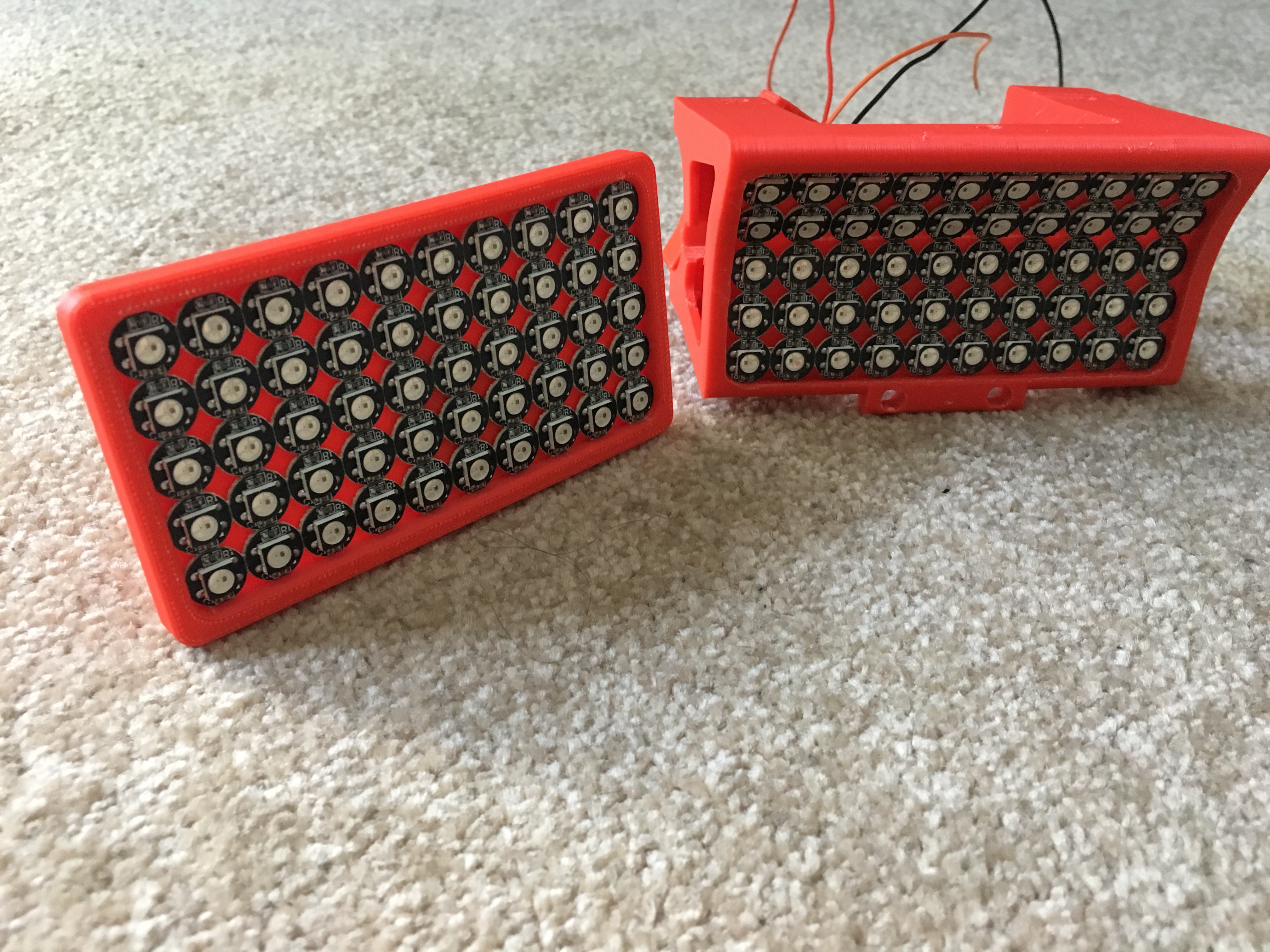
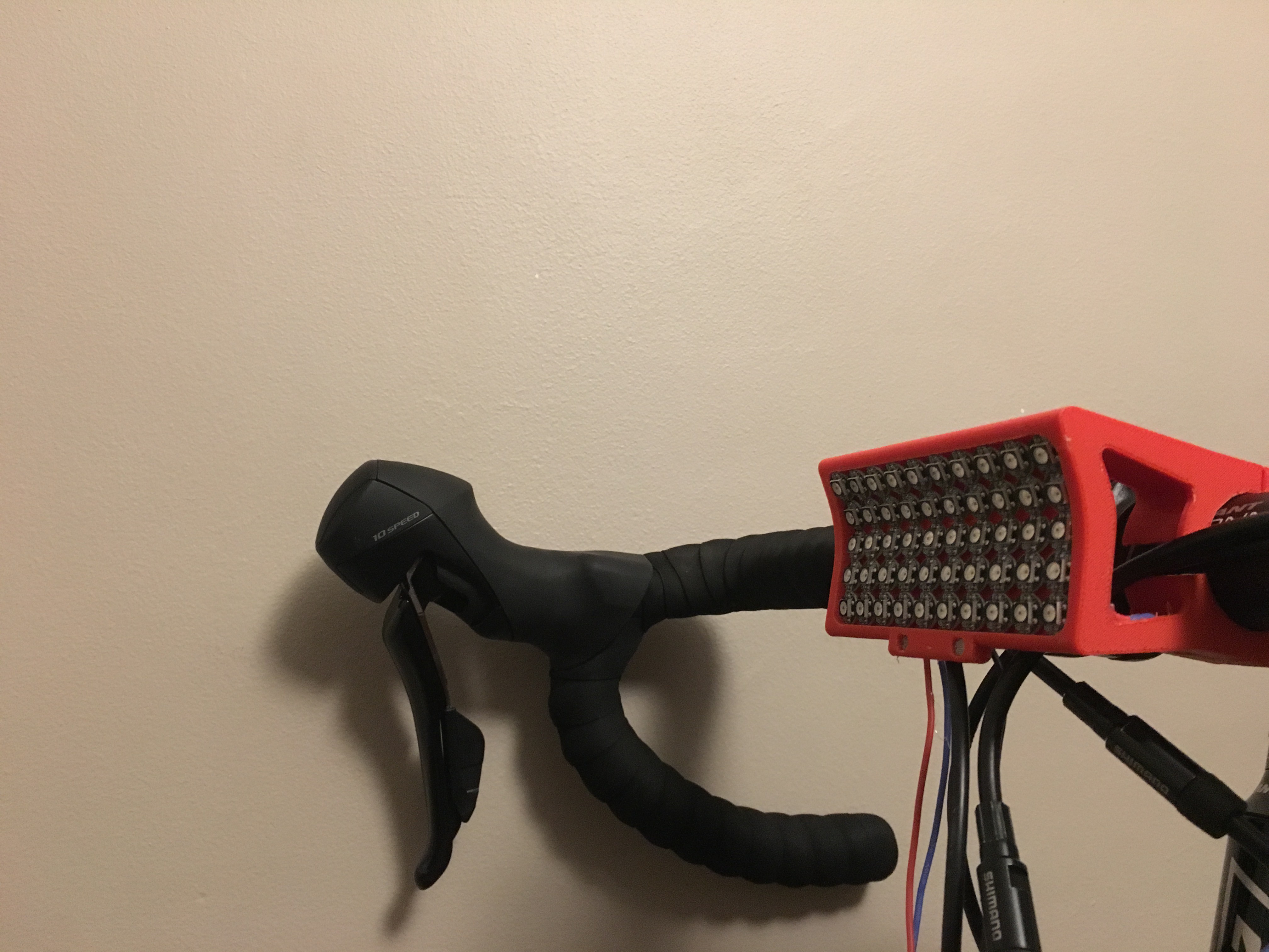
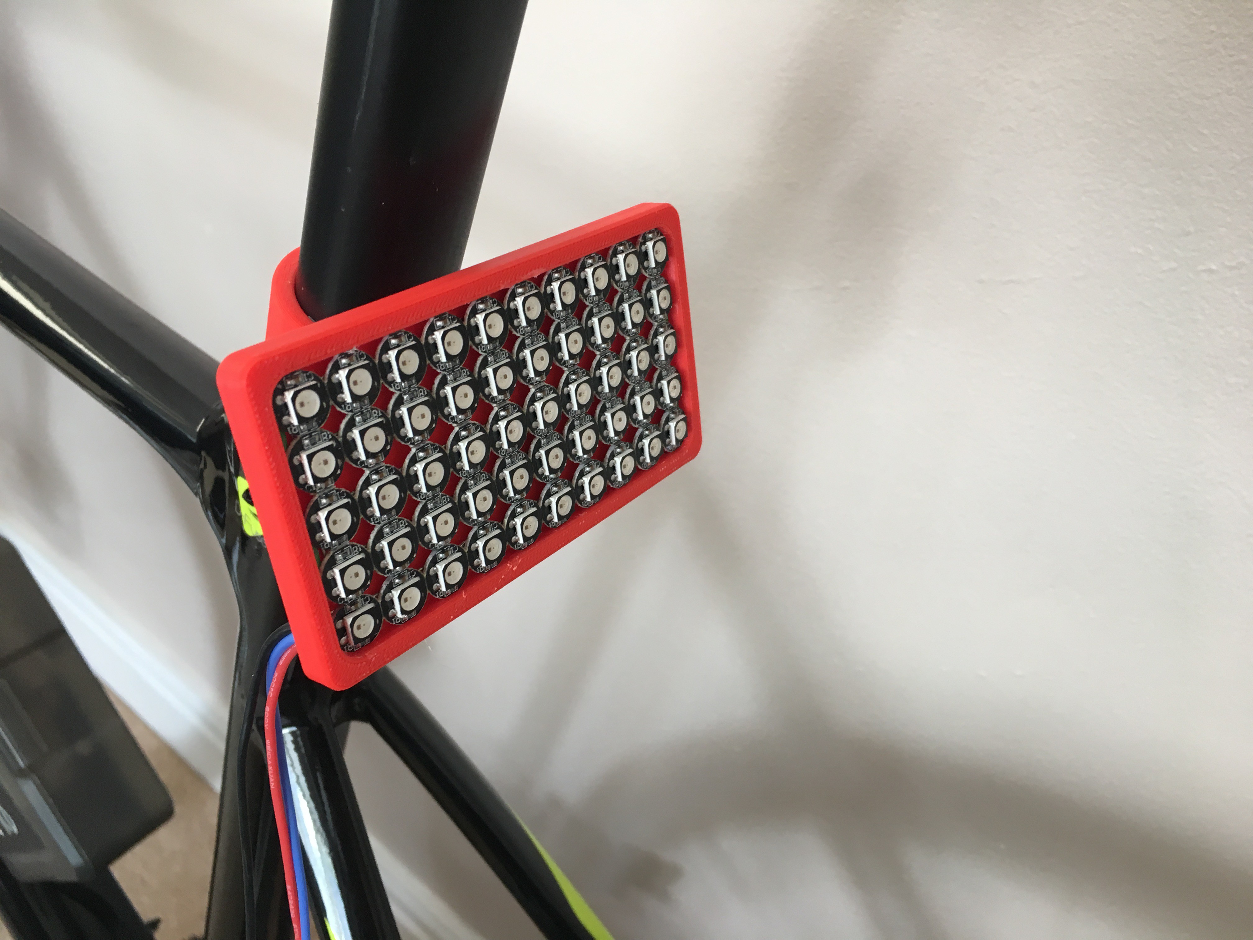
Let's start with FL and RL. I tried to make a simple design for ease of printing. However, it is not an easy task if we start thinking about the number of wires coming out and how to route them. Let me tell you something, I hate wires as they really affect aesthetics and no matter how you sort them, they are not part of the design when you first think about it. Wire routing is art, so my plan is to make them disappear!
As it can be seen, I have also added the LED matrix, but all rows still need to be connected. Now, patience and start soldering! I will treat the LED matrix as a single LED stripe, so only one 'for' loop will be needed to address all of them instead of two (rows and columns).
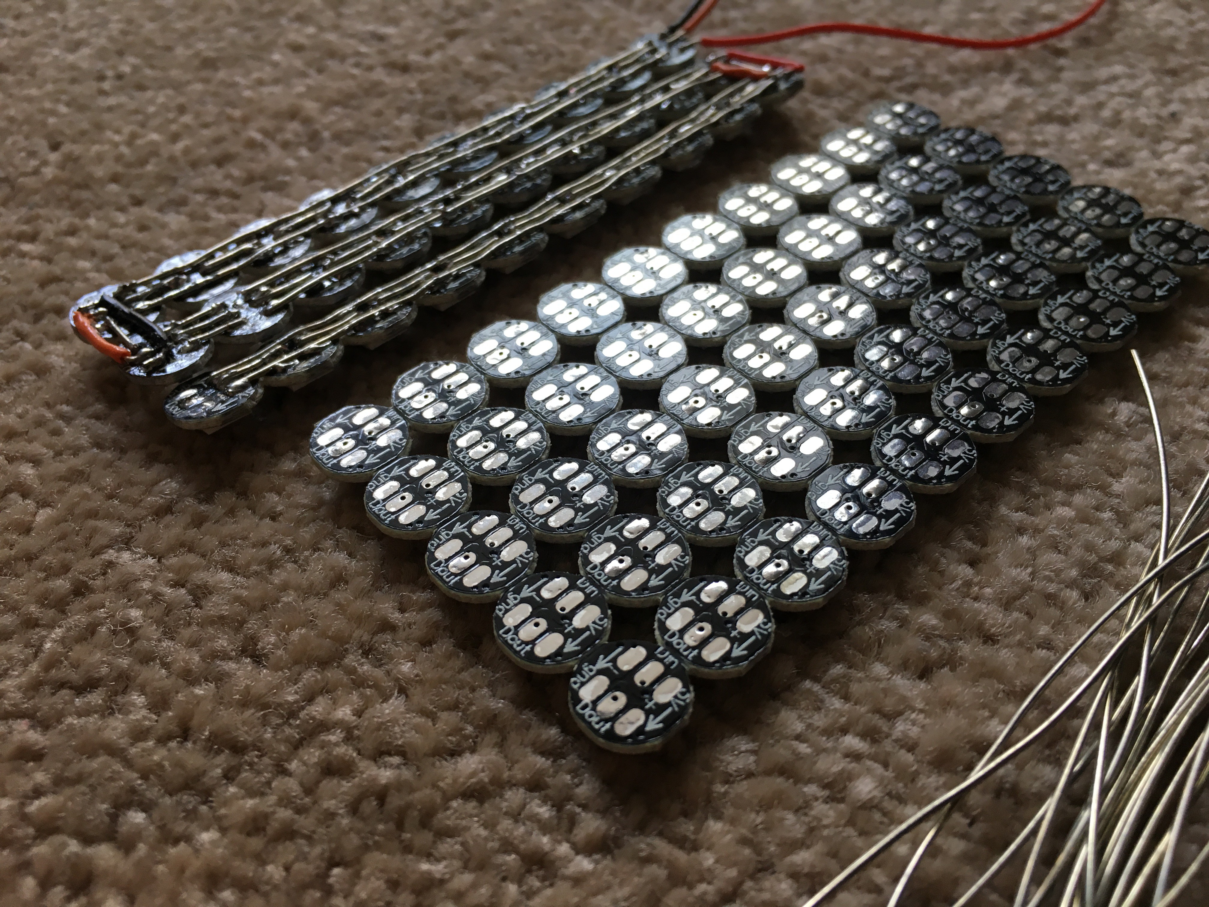
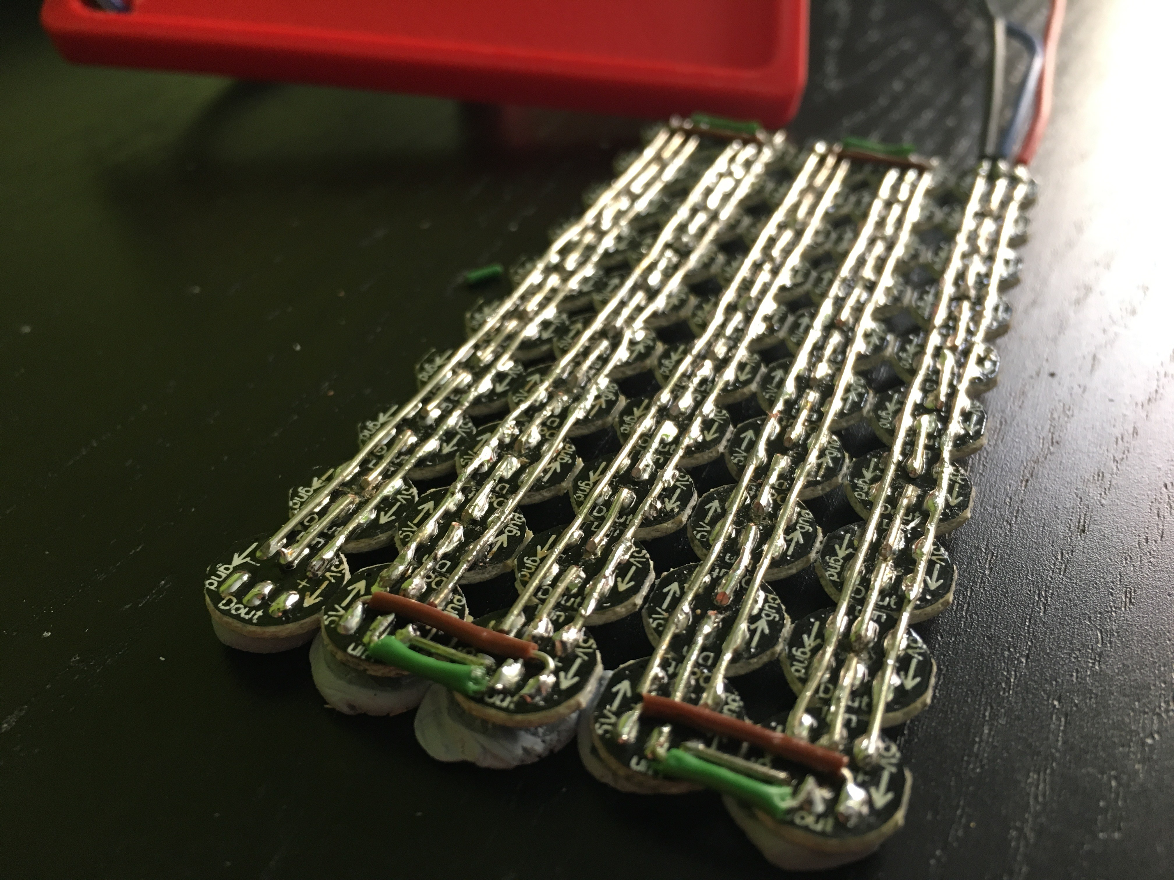
The best way I found to solder this LED matrix is to use some 'blu tack' or similar, so the matrix will be firmly attached to the bench.
Next step was to find a good library for Arduino. FastLED seemed to be a great choice, so I decided to check each LED to see if all of them are well connected. There is an example named 'Blink' that can be used to activate one LED each time and also to get familiar with the library itself. If you want to go further, I would suggest you to add a potentiometer to the setup, so you should be able to activate as many LEDs as you want by adjusting the knob.
I have to say that it was a pain!! Well, I managed to finish, so let's see how it looks like o the bike, but first check out the coupling system of the headlight. Different brackets would make it easier to adapt the system to other bikes. As it can be seen, two rows of headlight were tilted 30deg to provide light close to the bike too. I will give further details on this idea as soon as I test the light on real conditions.

I know they are very basic and it would be nice to make nicer designs, but I am now focused on making a working setup first.
As the last step, I decided to add four pushbuttons on a breadboard (emulating indicators, front light and brake light) and test my code. I had to make use of interrupts as you may see in the code and pushbuttons are internally set as pull-up inputs. I also tried to make it as simple as possible, so feel free to ask me if you have any question. I am still working on this stage, so please bear in mind that the code is not finished yet.
Now it is time to explain how I designed all different functionalities for lights. Let's start from basics... I know I am very repetitive, but I tend to forget and freak out:
Braking light - brakeLight()
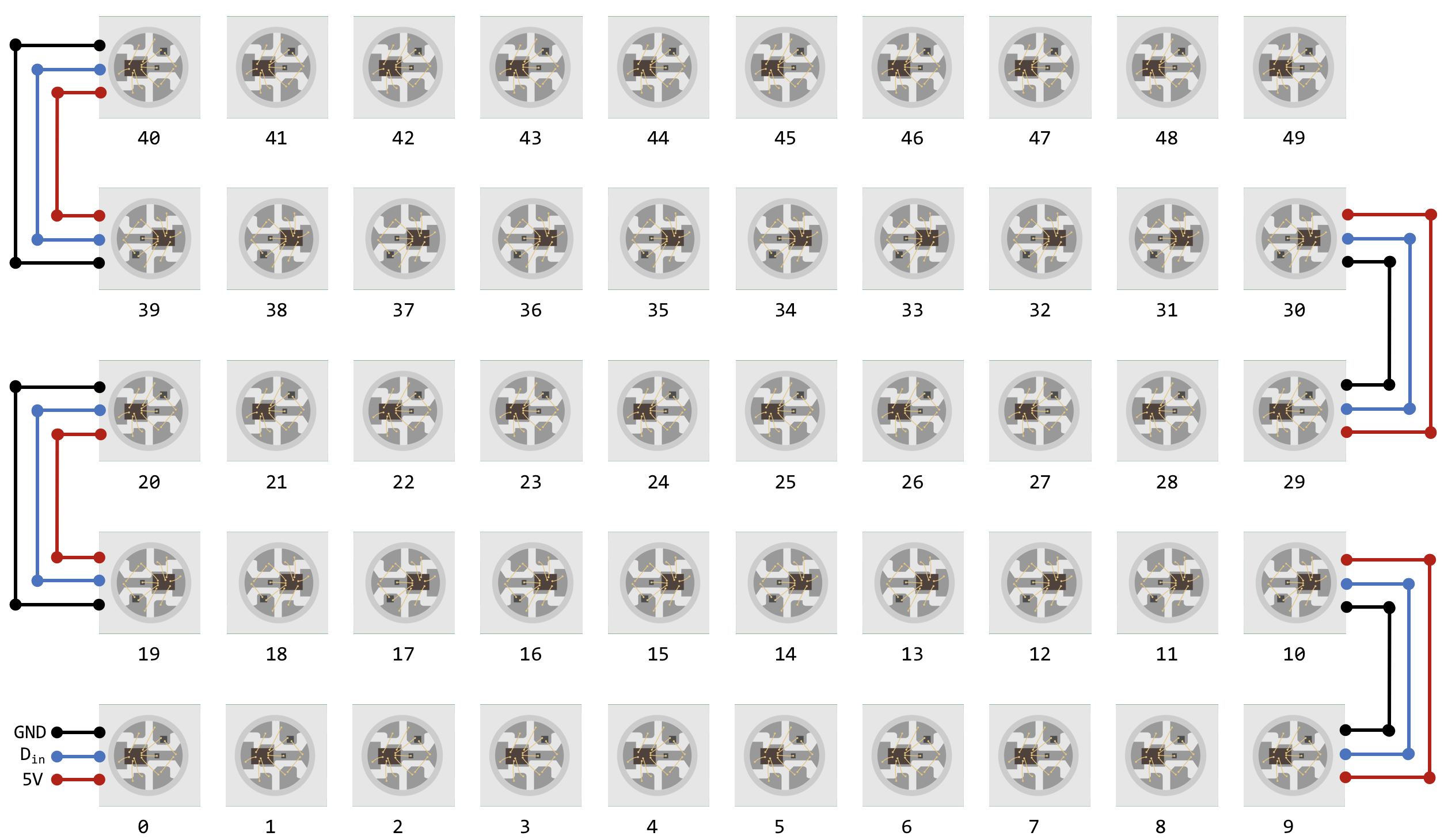
If you scroll up and check the diagram, the braking light circuit is just two pushbuttons connected to the same digital input pin. Hence, the braking light should be activated if any of the pushbutton is pressed. I am treating the WS2812B matrix as a single row of 50 LEDs, so the index should go from 0 to 49. Please see the diagram below, as graphics always help.
And here is the function that activates all LEDs in red:
void brakeLight(int k){
  FastLED.setBrightness(k);
  for (int i = 0; i<NUM_LEDS;i++){
  Rleds[i].setRGB(255, 0, 0); //Rleds - Rear Light LEDs
  FastLED.show();
  }
}
Beam Light - headLightOn()
Now that the braking light is working, you should notice that when the beam light is activated on a car, the braking light also does but with reduced brightness. In other words, another if statement should be enough to activate both lights at the same time. Here is the code for the beam light:
void headLightOn(int k){
  FastLED.setBrightness(k);
  for (int i = 0; i<NUM_LEDS;i++){
  Fleds[i].setRGB(255, 255, 255); //Fleds - Front Light LEDS
  FastLED.show();
  }
}
Indicators- indicatorOn()
Let's begin with a bit of a challenge! This is not hard because of the coding part, this is hard because you need to make it work! I love Audi's light matrix and I thought - why not?! It should be easy to switch on/off LEDs in cascade mode. In other words, on...off...on...off...got it!
After several trials, I managed to use only one function to activate the headlight and the rear light saving memory and reducing code lines!
void indicatorOn(int z,int j) {
  FastLED.setBrightness(20);
  for (int i = 0; i<=5;i++){

    //Front Light
    Fleds[(5-z)-i*j].setRGB( 255, 30, 0);
    Fleds[(14+z)+i*j].setRGB( 255, 30, 0);
    Fleds[(25-z)-i*j].setRGB( 255, 30, 0);
    Fleds[(34+z)+i*j].setRGB( 255, 30, 0);
    Fleds[(45-z)-i*j].setRGB( 255, 30, 0);

    //Rear Light
    Rleds[(5-z)+i*j].setRGB( 255, 30, 0);
    Rleds[(14+z)-i*j].setRGB( 255, 30, 0);
    Rleds[(25-z)+i*j].setRGB( 255, 30, 0);
    Rleds[(34+z)-i*j].setRGB( 255, 30, 0);
    Rleds[(45-z)+i*j].setRGB( 255, 30, 0);
    FastLED.show();
    delay(70); //Delay for cascade effect
  }
  delay(200); //Delay to start switching off with the same effect

  FastLED.setBrightness(20);
  for (int i = 0; i<=5;i++){

    //Front Light
    Fleds[(5-z)-i*j].setRGB( 0, 0, 0);
    Fleds[(14+z)+i*j].setRGB( 0, 0, 0);
    Fleds[(25-z)-i*j].setRGB( 0, 0, 0);
    Fleds[(34+z)+i*j].setRGB( 0, 0, 0);
    Fleds[(45-z)-i*j].setRGB( 0, 0, 0);

    //Rear Light
    Rleds[(5-z)+i*j].setRGB( 0, 0, 0);
    Rleds[(14+z)-i*j].setRGB( 0, 0, 0);
    Rleds[(25-z)+i*j].setRGB( 0, 0, 0);
    Rleds[(34+z)-i*j].setRGB( 0, 0, 0);
    Rleds[(45-z)+i*j].setRGB( 0, 0, 0);

    FastLED.show();
}
}
The first thing I need, is to figure out where do I want to set my starting point, which is one column further than the middle column, where LED 5 is. If LI is activated, LEDs corresponding to that column are 5, 14, 25, 34 and 45 and the index needs to go from 0 to 5 as establishing a numerical relationship between the aforementioned numbers is not recommended. The index increases in some of the rows while decreases in others (yes, go back and check the diagram). However, if RI is activated, LEDs corresponding to that column are 4, 15, 24, 35. Now the addition of 'z' makes sense as its values will be 1 for RI or 0 for LI.
Another parameter (j) is introduced to define the direction (left, -1, or right, 1) depending on which indicator is activated. Bear in mind that both lights have exactly the same layout, hence they need to have opposite signs for the indexing.
Let me show you a video of different functions I managed to program. I could not add all LDRs as I am still working on this stage.
Next update I will show you a fully working smart lighting system...on the road!
UPDATE - 01/09/2018
I know it has been a while, I am sorry. My health condition was not the best in the last two months but now I am fully recovered!
Minor changes have been carried out on the smart lighting system:
- I managed to have a fully working LDR for environment light sensing. However, when the beam light is activated, the brake light flickers. Maybe using an Arduino Uno/Nano is not enough or my way of programming is not the ideal one for this case. Anyway, I am currently optimising the code to make sure that it is robust and it does the job properly. You can find it on GitHub!
- I am planning to upgrade the controller too. I am currently testing my code with a lot of issues. It is very annoying and very time consuming... BUT I AM LEARNING! I will leave it there as this controller brings more features...
- I had some wiring issues with the LDRs and I spent some time redesigning it. The headlight works very well, but one of the LEDs needs to be soldered again. That is going to be a proper pain. I am currently working on it!
Q&A Section
Are you planning to update the headlight and rear light models?
That is for sure! As I mentioned before, I am working with very simple and easy to make designs. On the other side, the headlight requires a lot of time and material. I decided to make the least prototypes as possible as this world is already facing a huge problem with plastic waste. I would love to use recycled plastics for this models, using methodologies like in Preciousplastic while considering the amount of energy spent to recycle and how to generate energy using alternative ways.
Discussions
Become a Hackaday.io Member
Create an account to leave a comment. Already have an account? Log In.