 Javier Betancor
As this log entry says, I am now upgrading the current power generation setup. Please find below the goals for this stage:
- Aluminium pinion and spur gear manufacturing.
- Aluminium motor bracket.
- Explained power generation circuit.
So, why Aluminium everywhere? Let me show you a picture:
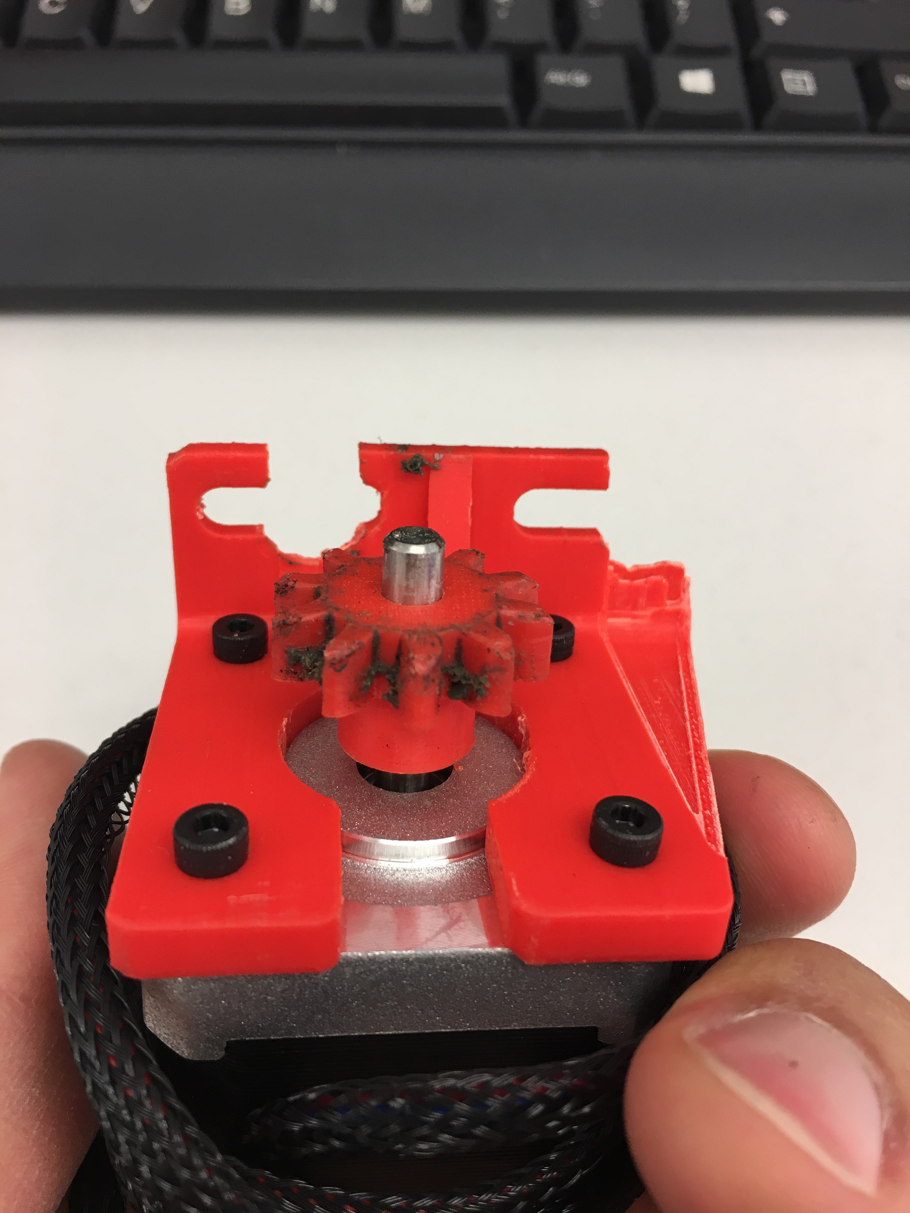
Yes, I was about to reach my working place and after an unexpected bump at 40 km/h that happened. The pinion is dirty because I tried to add some grease for noise cancellation and also for less friction as I am dealing with ABS.
That made me think. One of the main topics of my dissertation is Vibrations and Control, so let me give you a practical explanation about what (I think) really happened. Imagine you have a racket and a ball. For some reason you feel lazy and decide to attach a short elastic string to the racket and to the ball, like paddleball. Then, you start playing and I guess you will find fairly easy to predict where is the ball going to hit it.
The situation above can be described as a one Degree Of Freedom (1 DOF) system under ideal conditions, so the ball can oscillate only through one axis. That is the bike and the road. Well, now let's make it a bit more complicated by cutting the string and adding another ball (the motor + bracket). We will consider that the second ball (the furthest) is static in the air waiting to be hit. This is also know as a 2 DOF system.
The racket hits the first ball and this one will hit the second one and come back because of the string. By that time, the second one will be forced to change its trajectory while going up because the first ball came back and is being hit again by the racket. Now, the first ball will hit a MOVING second ball. That means more energy when they collide. If we add more time and also real conditions to this experiment, you will see that it is almost impossible to hit the ball because one depends on the other. In other words, this system is unstable.
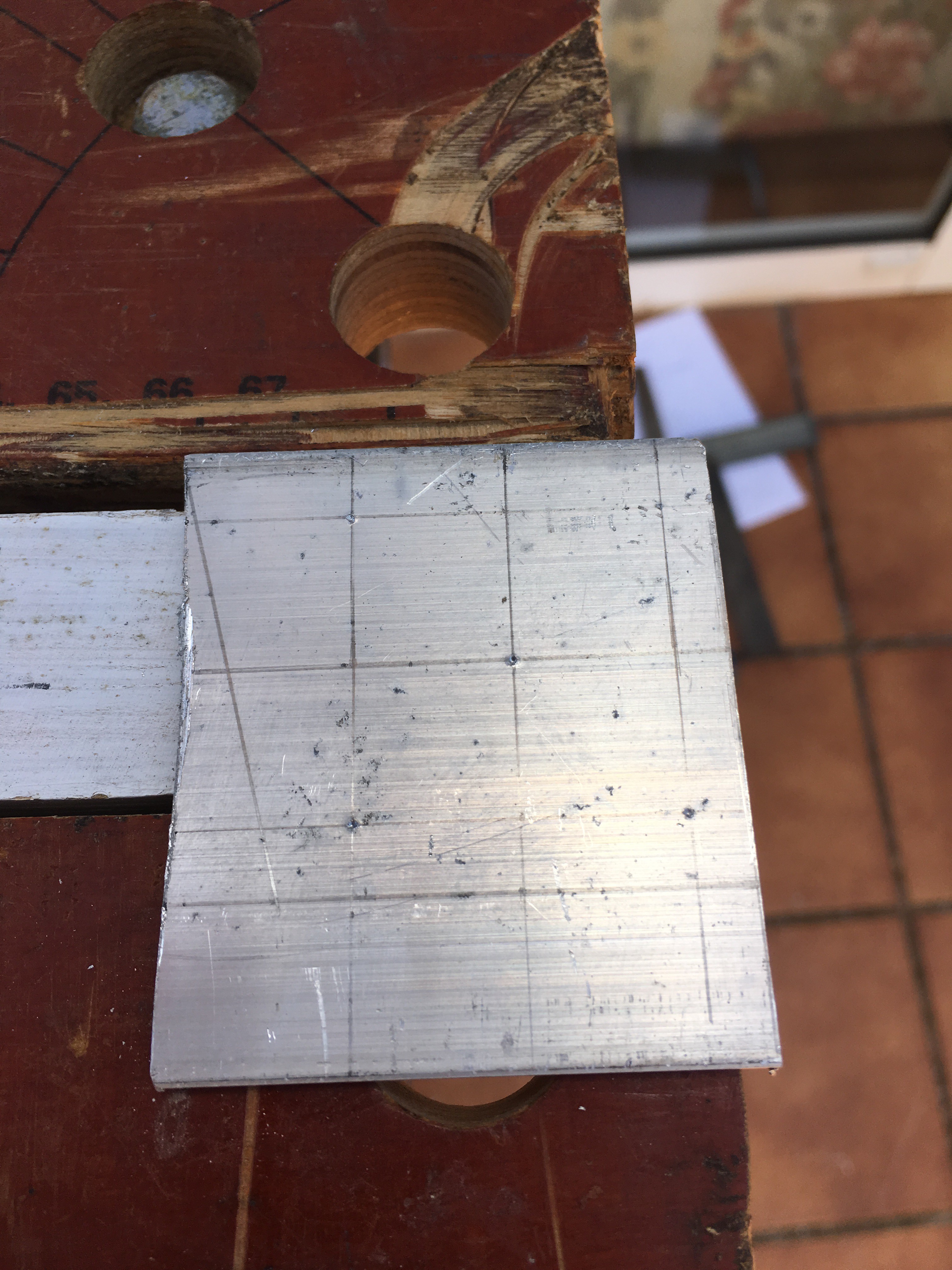
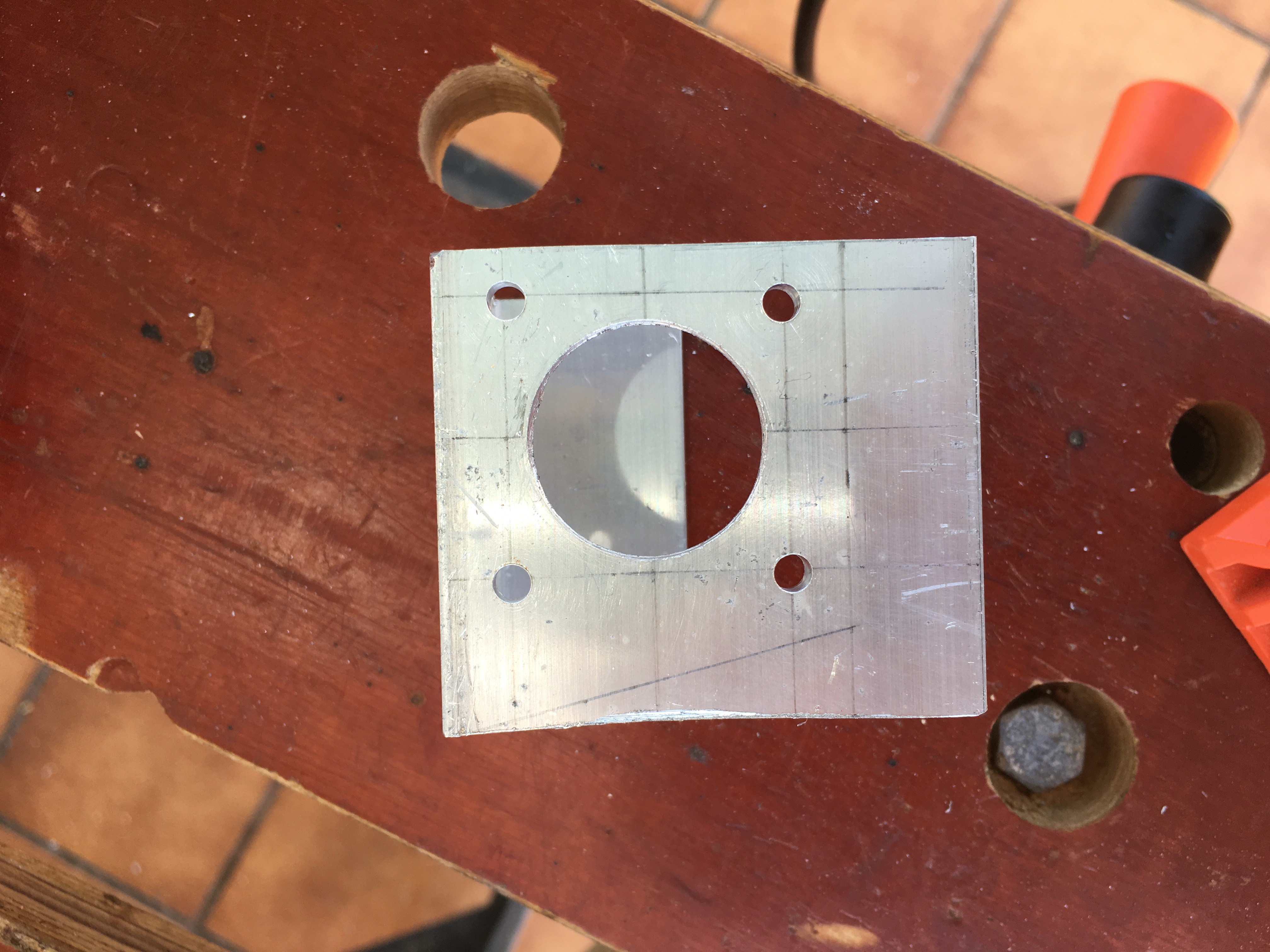
So, I had two choices: to implement a controller or make the bike + motor + bracket to oscillate as a single system. The idea of a controller is senseless since I can use a stiffer material for the motor bracket. Hence, my father had a u-shape aluminium profile back in home and cut a bit for me (pictures below).
For this part of the stage I used:
- Motor bracket drawings (GitHub)
- Angle grinder + steel disc
- Driller with several drills (from 1 to 6)
- 25mm diameter hole saw drill bit
- File tool
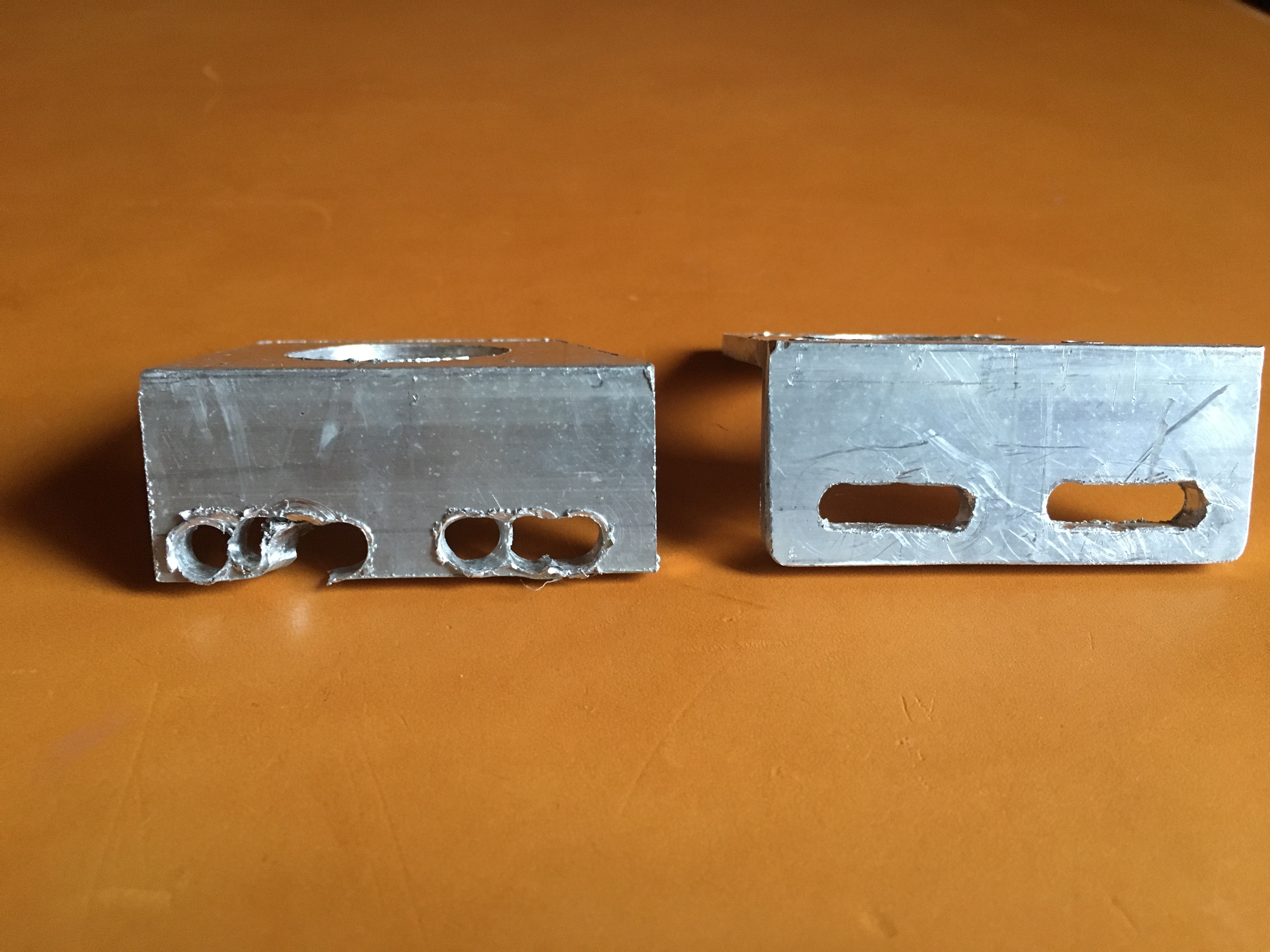
But, not everything was success! On my first try I made a little mistake by placing the bracket holes too close to the edge and this is what happened considering that tools are not perfect and I am learning:

Now, regarding the pinion and spur gear I have been in touch with manufacturers here and there and none of them want to build just one unit for prototyping, which makes sense but I do not need more than one unit. I am still trying to make a deal but in the meantime I managed to reinforce both gears and make them stronger by using a full solid plastic structure and adding a grub screw to the pinion, so it will be completely fixed to the stepper shaft. Components used for this part of the stage are the following:
- Updated 3D-printed models of the reinforced gears (CAD files on GitHub!).
- 1 x M3 Allen grub screw + tool
And this is how gears looks like:
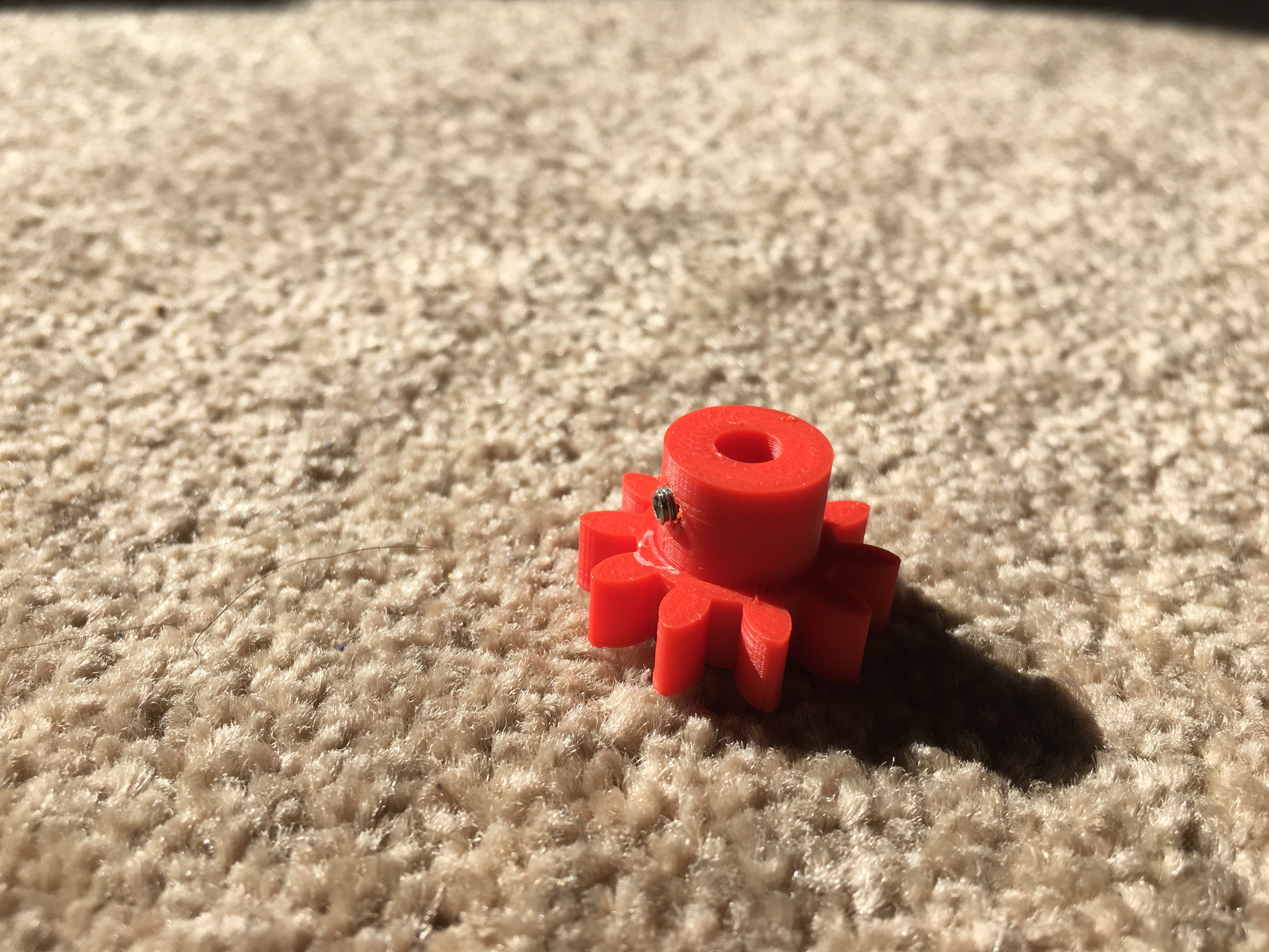
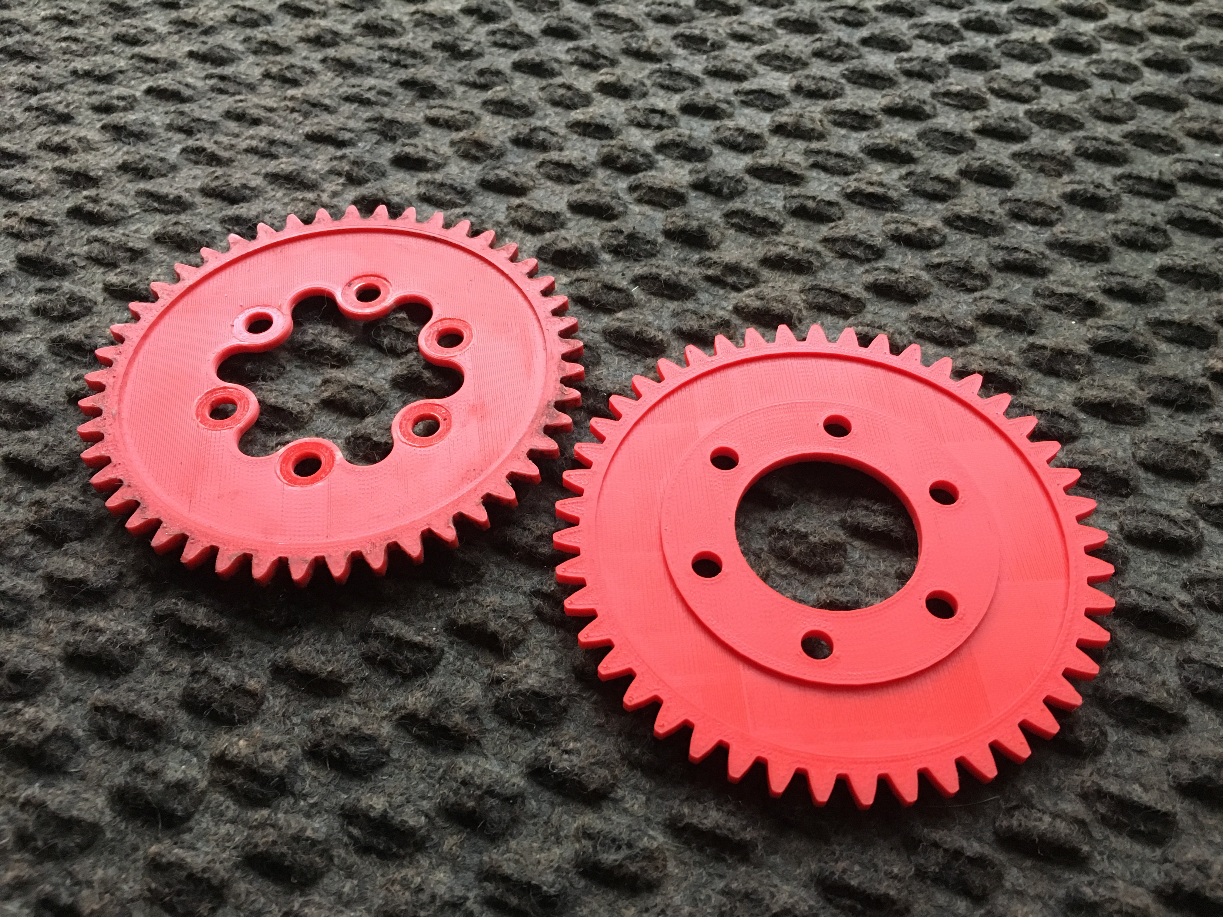
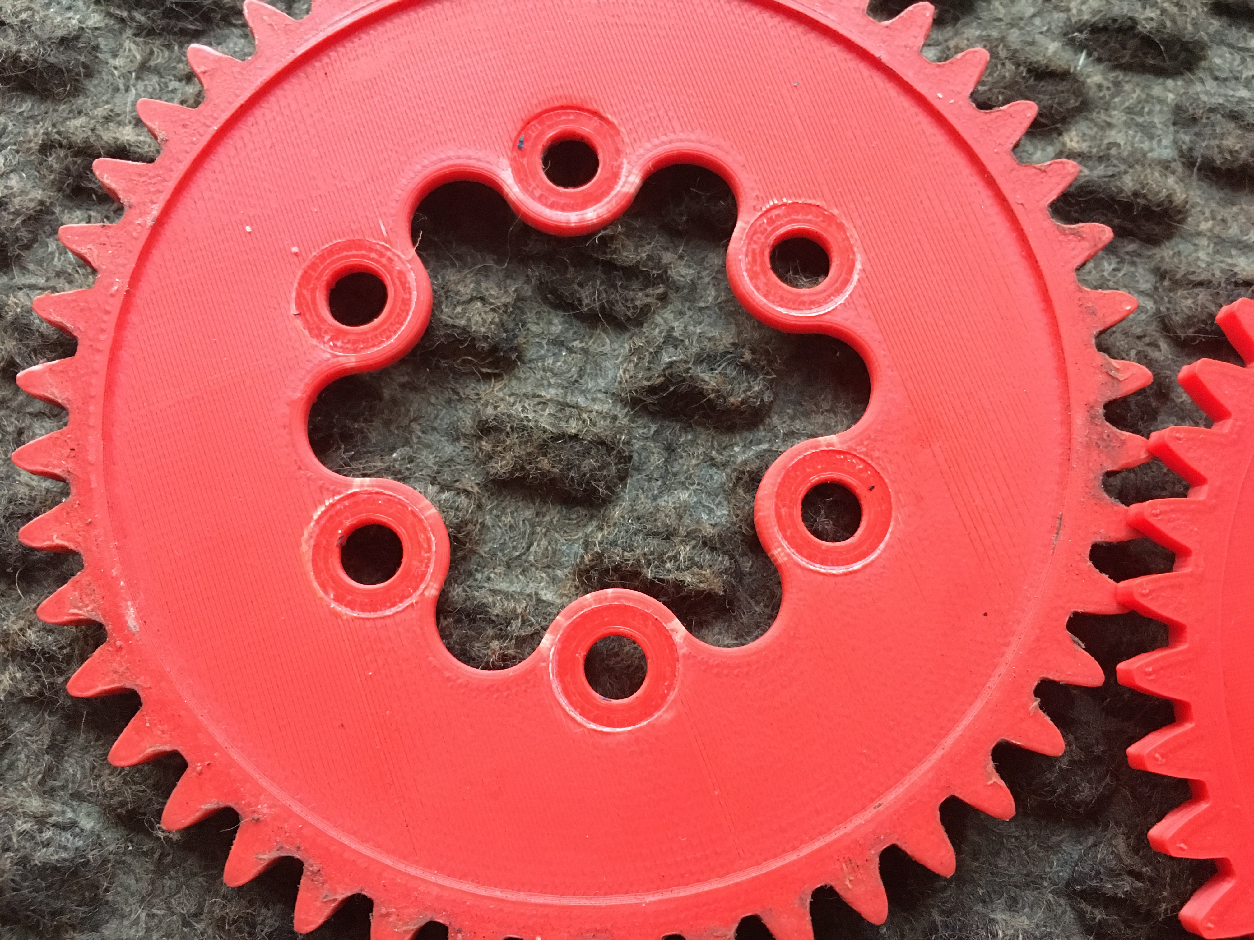
You can notice the effect of the pressure generated by the washer as it was about to break the old spur gear. You can also appreciate it in this picture:
By the way, I already did more than 200km with the same gears. I think it is a very good figure considering that we are talking about medium quality 3D-printed parts!. Well, this is how it looks like on the bike!!!

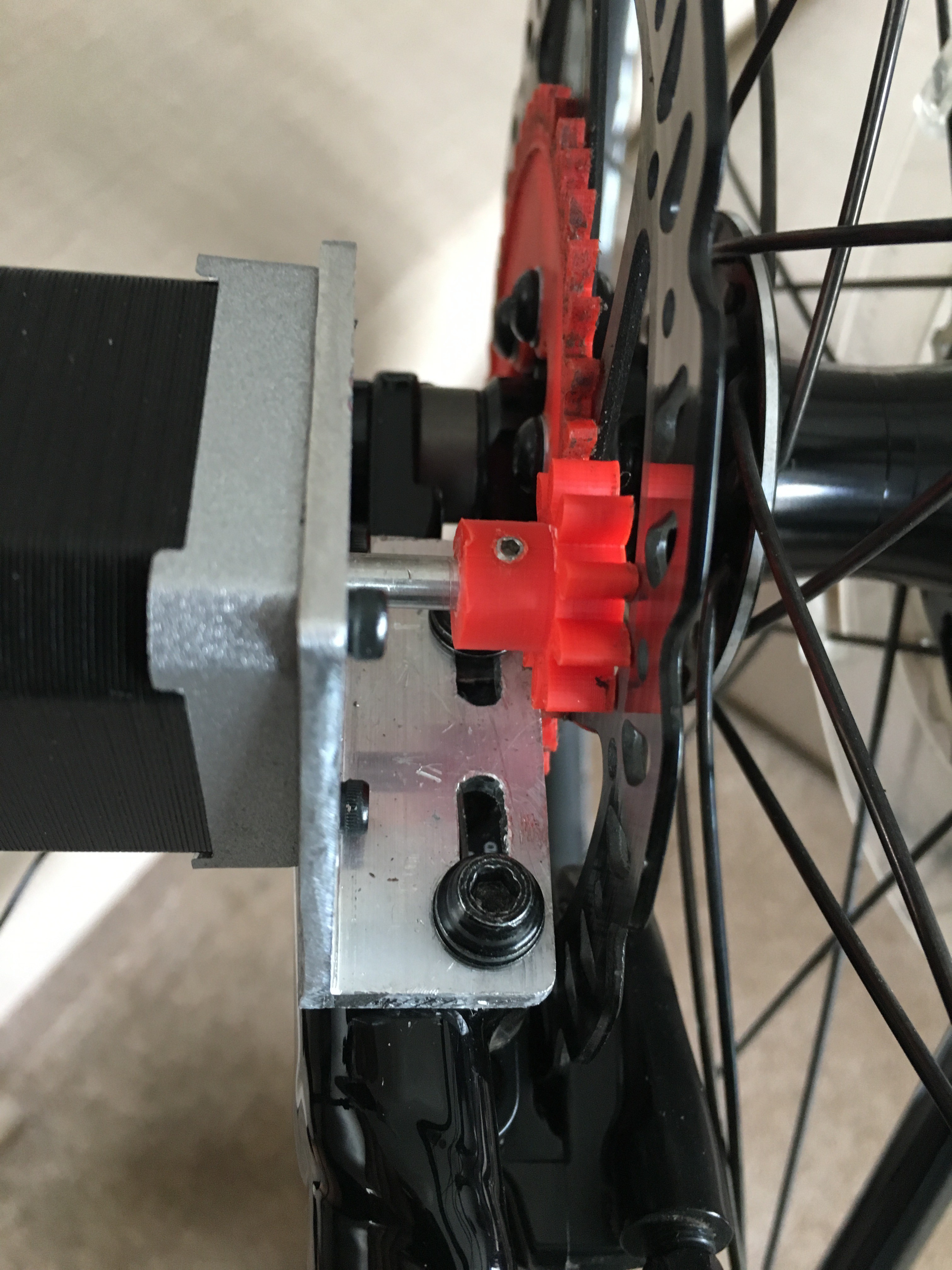
I tested it on the road and...IT WORKS!!! The bike + motor bracket + stepper motor works as a single system, no oscillations at all!
Now, the last bit for this upgrade: the rectification circuit. First of all, thank you hex4def6, electrobob and K.C. Lee for all your different ideas regarding the capacitor issue. I really appreciate it and it also made me think...a lot! I would like to share my thoughts with all of you.
I finally decided to use a 100uF@25V smoothing capacitor. I made my choice based on this post:
https://www.electronics-tutorials.ws/diode/diode_6.html
I also managed to simulate it using PartSim, but first I measured the max. voltage with no load, 50V and also the load resistance, 1.12MOhm. I also simulated it using two coils in Falstad. (Import files on GitHub):
http://www.partsim.com/simulator/#154948
Now, my options to store most of the generated energy based on your suggestions are:
- TL431 Shunt regulator - Nice option but its maximum current is 100mA, so it need to be used in conjunction with a PNP transistor to be able to handle more power. (http://www.bristolwatch.com/ccs/TL431A4.htm)
- MPPT - Excellent choice. I already bought one from Amazon (https://www.amazon.co.uk/SODIAL-Controller-Step-down-Charging-Display/dp/B076BFCGG6/ref=sr_1_3?ie=UTF8&qid=1534878476&sr=8-3&keywords=5A+MPPT) I think it would be nice to try, but it is bulky and I believe I have more choices.
- LM78XX or LM731 linear regulator - Not very efficient for this purpose as a buck converter will do the job perfectly (https://www.youtube.com/watch?v=CEhBN5_fO5o&frags=wn).
- What I had since the very beginning is a 'Step-down Buck Converter Module' (https://www.ebay.co.uk/itm/DC-6-24V-12V-24V-to-5V-3A-Car-USB-Charger-Module-Buck-Step-Down-Converter-Phone/401265883616?hash=item5d6d4f79e0:g:OjoAAOSwQctbMTOy) with the MP2315 synchronous step down converter embedded (https://www.mouser.com/ds/2/277/MP2315_r1.01-478439.pdf).
I think I am already making the most of it. To prove it I decided to quantify the amount of energy stored by charging my phone (iPhone 6S, 1,715mAh battery) instead of a power bank. Below you will find a screenshot of the phone before and after the trip:
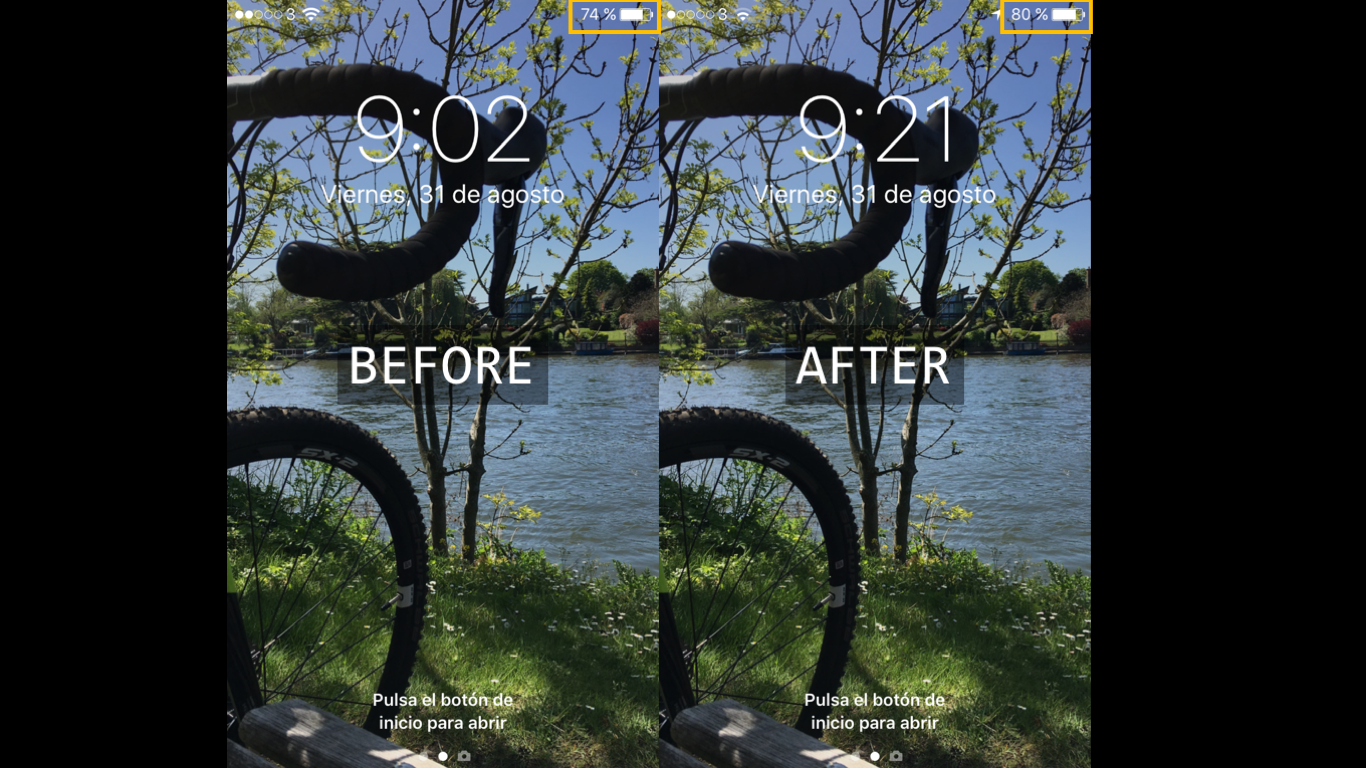
Yes, I know. I could have charged the phone for that time and that is it! That is why I decided to take my TomTom watch with me. From picture below you will be able to figure out the distance covered, time and speed:
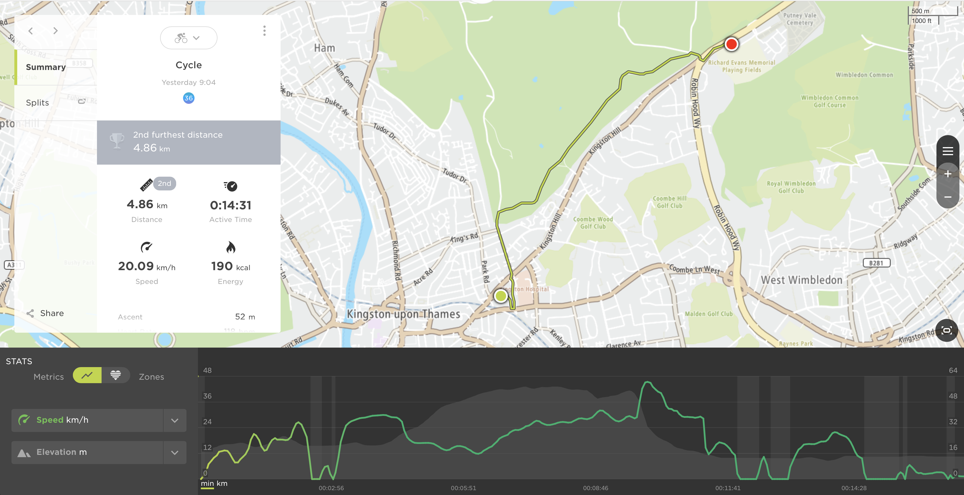
To sum up, 4.86Km in around 15min for a 6% charge. All in all, I am very happy considering that I could have also changed the motor for the same one but more powerful (bigger coils), but I will do it once I finish the project.
Just to let you know, NO DRAG AT ALL. I cannot prove it, but I could have felt it. Thank you for spending some time reading about this entertaining adventure and I hope you like it! See you on my next log!
Discussions
Become a Hackaday.io Member
Create an account to leave a comment. Already have an account? Log In.