 Lucy Fauth
Introduction Video:
0%
0%
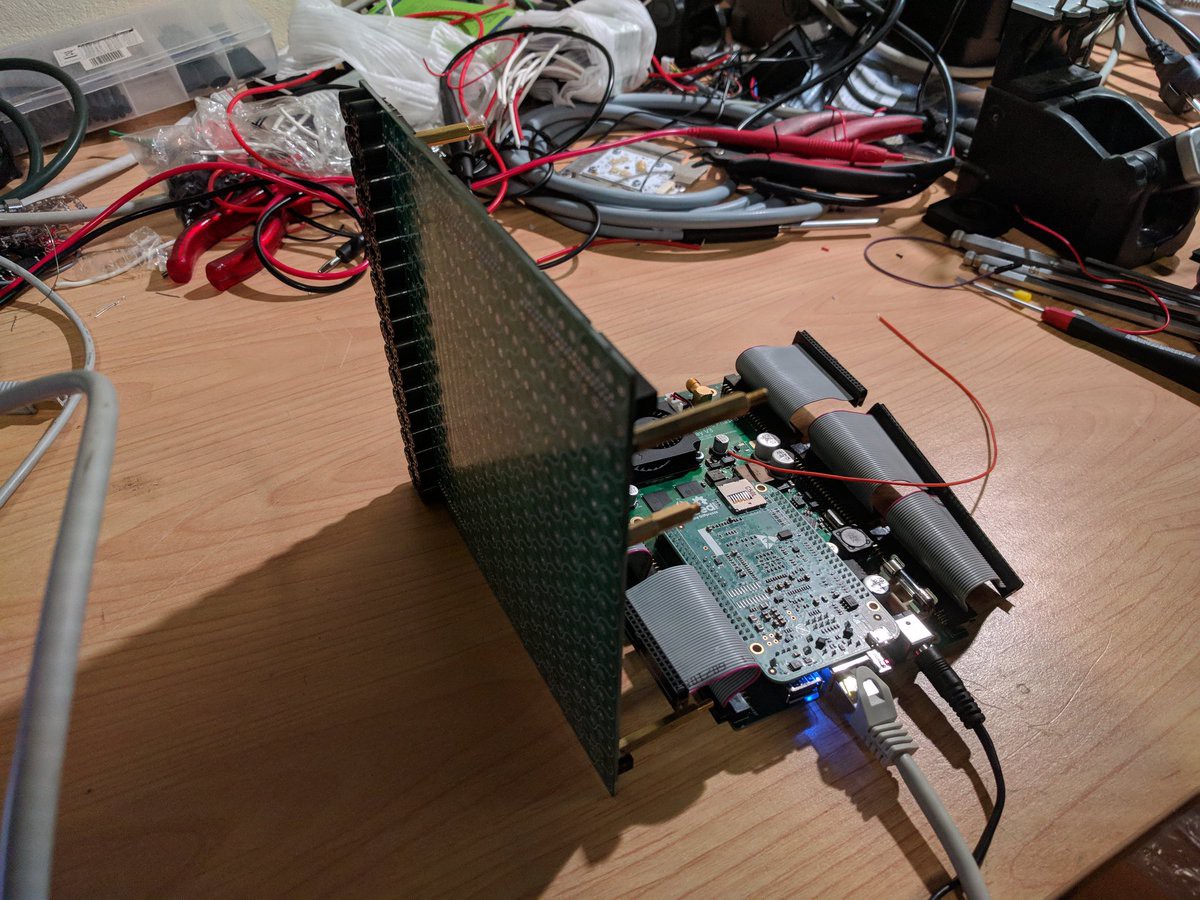
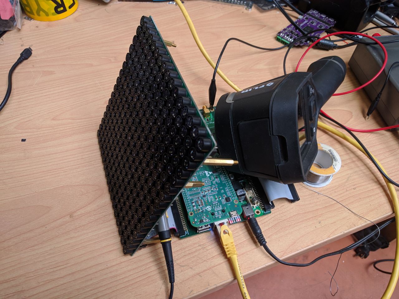
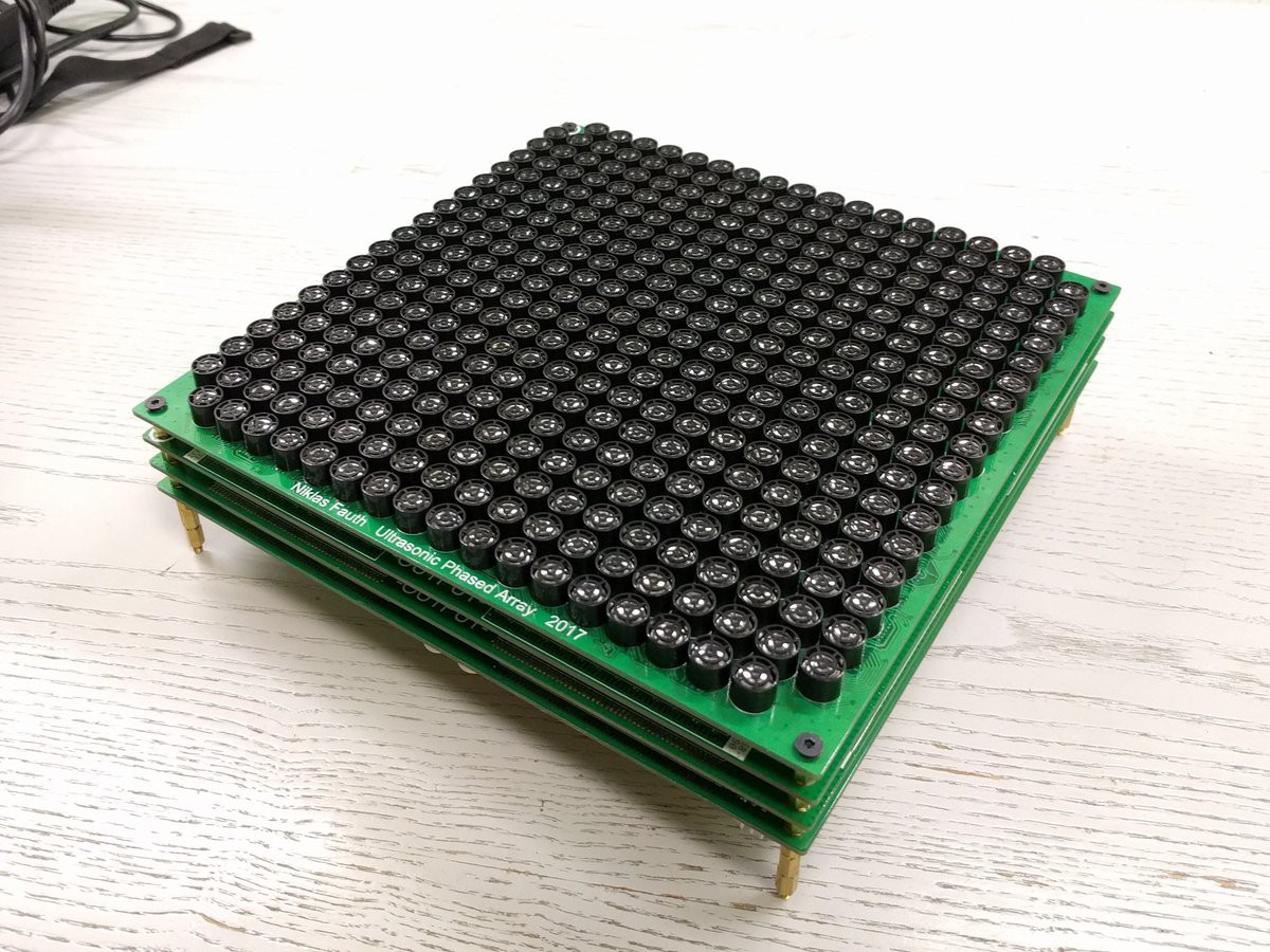
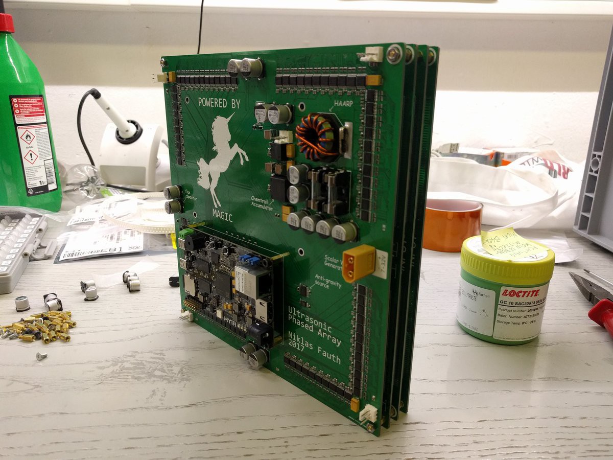
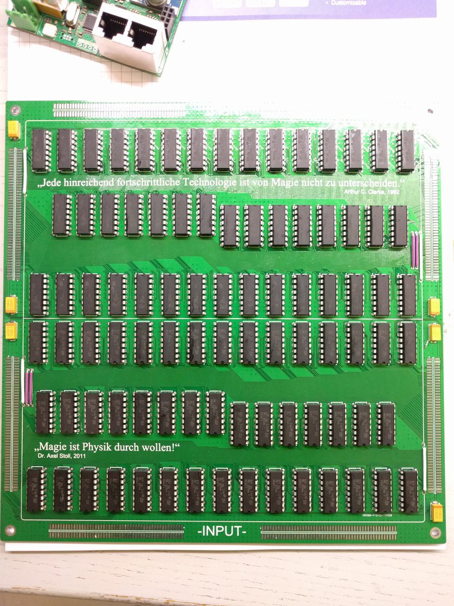
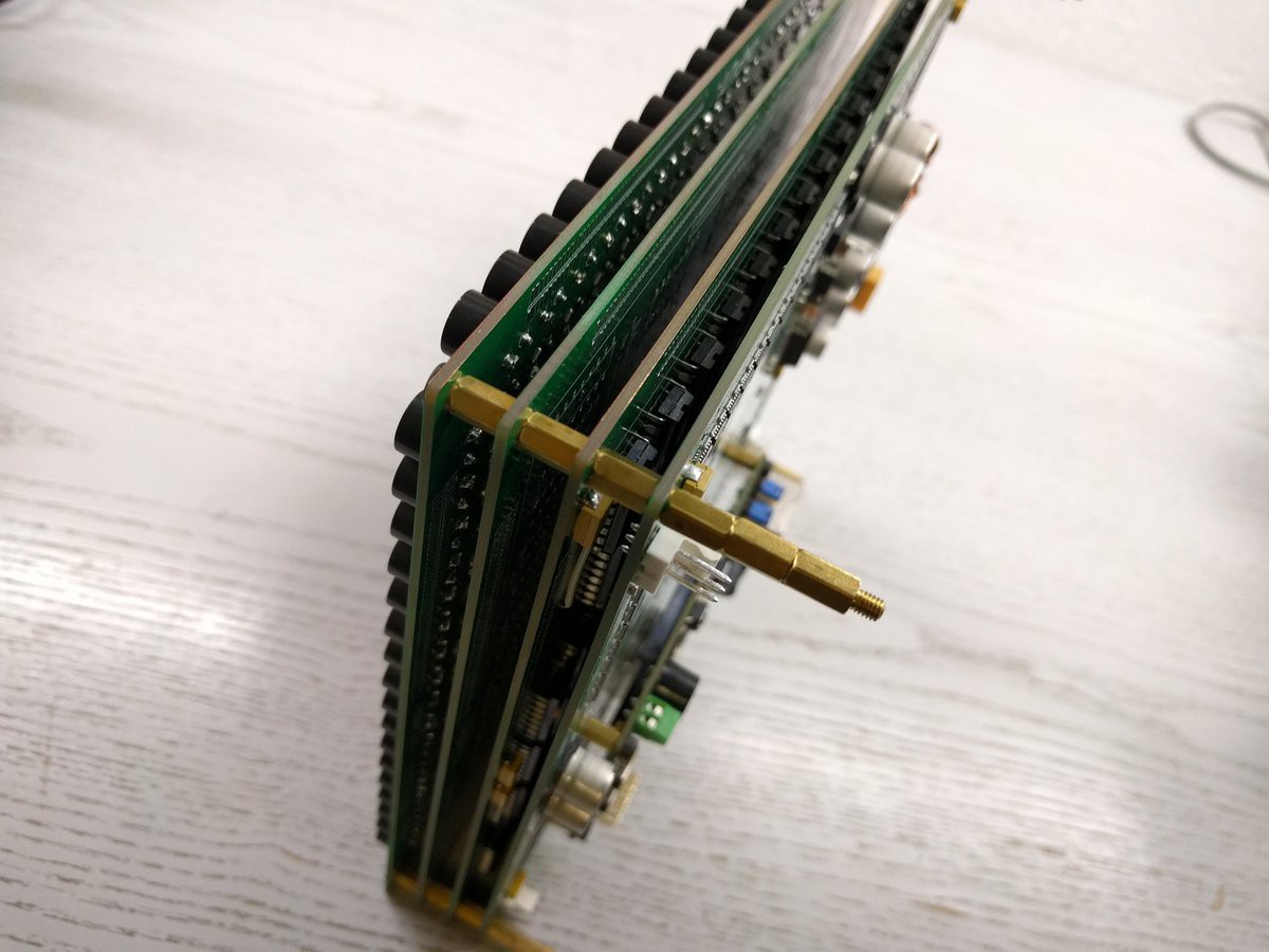
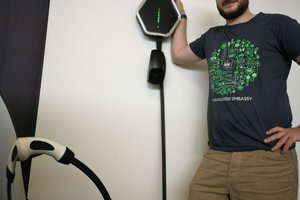
Open Source Ultrasonic Phased Array
Documentation of the 3rd generation of my ultrasonic phased array project. Levitating stuff, directional speaker, haptic feedback and more!
Become a Hackaday.io member
Already have an account? Log in.
Just one more thing
To make the experience fit your profile, pick a username and tell us what interests you.
Pick an awesome username
hackaday.io/
Your profile's URL: hackaday.io/username. Max 25 alphanumeric characters.
Pick a few interests
Projects that share your interests
People that share your interests


 Mastro Gippo
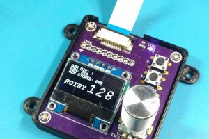
 CriptasticHacker
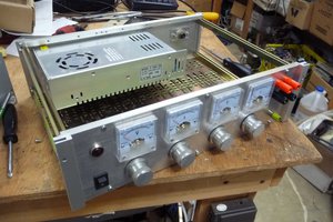
 Rue Mohr
 Jarrett
Did you ever get this to something you could sell on Tindie? I'd try it at the right price.