Close
0%
0%

Portal Point Generator

An efficient and compact generator that can be coupled with wind turbines or water wheels to produce upwards of 100W

Public Chat
Similar projects worth following
Originally designed and built to take on an expedition to Antarctica coupled with a wind turbine. Portal Point was one of the locations in Antarctica that this was set up to generate power to charge electronics, and hence named after it.

I was unable to find a cost-effective generator and using motors backward to generate power seemed too wasteful because of their inherent detent torque. I decided to go back to fundamentals and build a turbine would give the maximum possible output for its size.

This generator was used in Antarctica along with CFA2018 and the organization 2041 to generate power and power our electronics. It goes to show the resilience in 3D printed parts and what amazing things this technology can do in the future and play an important role in creating a sustainable future.

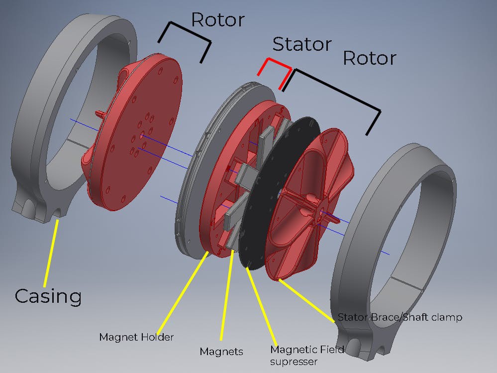
What is a Dual Axial Flux Generator?

A dual axial flux generator consists of powerful magnets placed on either side of a fixed stator winding, like a sandwich creating a very strong magnetic flux between them, and thus inducing a powerful EMF in the stator winding when in motion. Since the magnetic flux is axial to the output shaft, it is an axial flux generator, unlike a radial flux generator like that most commonly found in DC motors that are converted as dynamos.

I chose to build this kind of generator, since it creates a dense magnetic field and makes the most efficient use of the magnets. There is hardly any magnetic flux leakage outside the generator itself.

Another upside is that, it makes the generator flat, and is easy to construct, as well as integrate into power generation projects.


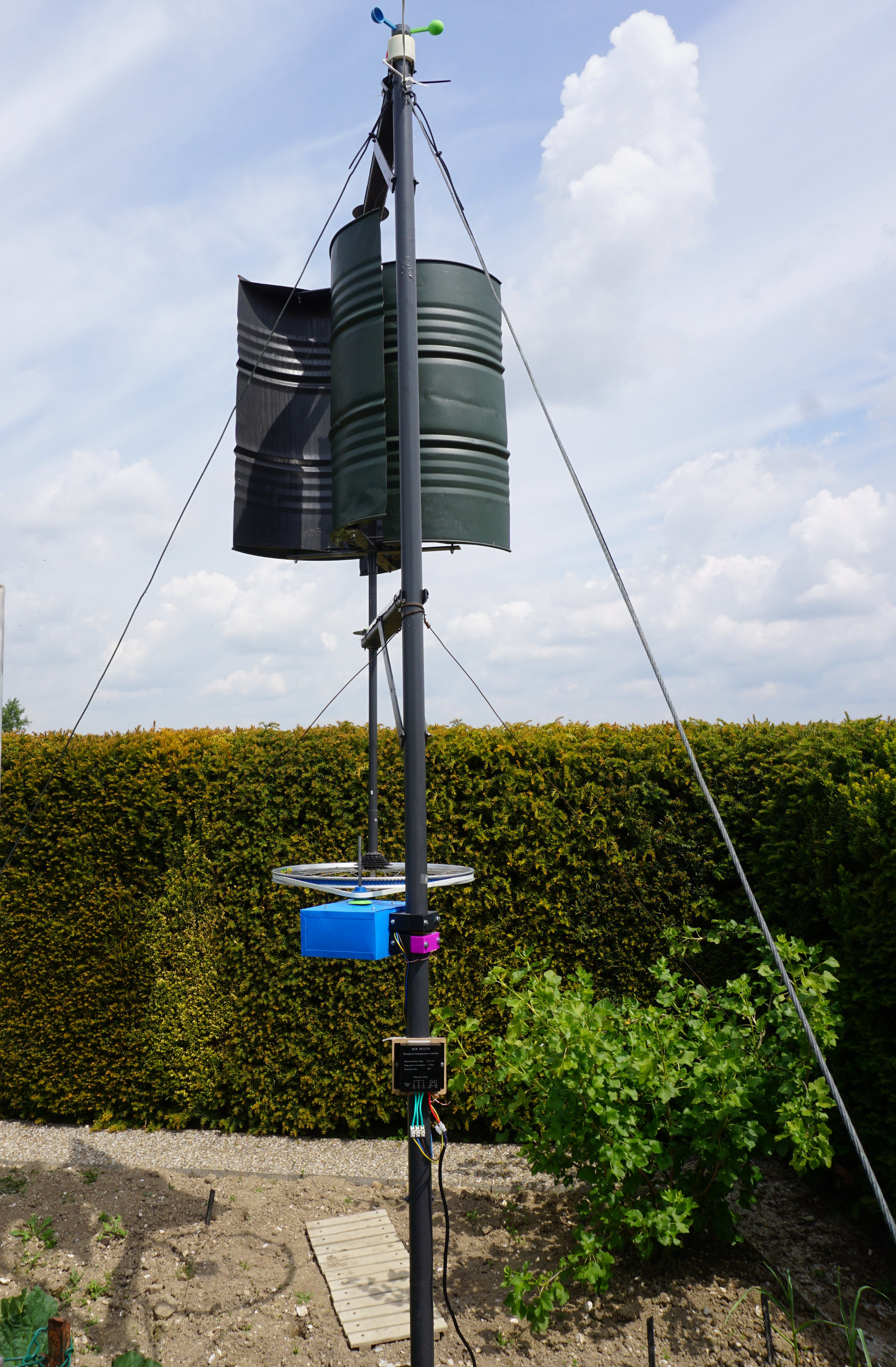
In the expedition to Antarctica,  I coupled this along with a Helical Wind Turbine Design (https://www.thingiverse.com/thing:99132) to create a Wind Turbine we could use to charge our electronics and equipment with.  In this documentation I shall also outline coupling the generator to the wind turbine project as well. 

Generator V2_WIP.stp

Heavily WIP CAD file on V2 generator

stp - 2.88 MB - 11/30/2018 at 11:32

Download

Generator.pdf

Exploded view of generator V1

Adobe Portable Document Format - 250.37 kB - 11/02/2018 at 13:25

Preview
Download

Feild stopper.dwg

DGW of MS Feild Stopper Generator V1

DWG Drawing - 199.14 kB - 11/02/2018 at 13:25

Download

Feild Stopper Drawing.pdf

PDF for MS Feild Stopper Generator V1

Adobe Portable Document Format - 3.20 kB - 11/02/2018 at 13:25

Preview
Download

Portal Point Gen V1.rar

Autodesk Inventor Pack&Go Files

RAR Archive - 20.84 MB - 10/22/2018 at 14:05

Download

View all 22 files

  • 16 × N52 Neodynium Magnets 40x20x10mm
  • 3 × 30 AWG Enamel insulated Copper Wire (M)
  • 1 × 50A 3 Phase Bridge Rectifier
  • 250 × M4 Threaded Road (mm)
  • 1 × 1.2mm Mild Steel Sheet 200x400mm

View all 10 components

  • Open Source FTW

    Vijay09/10/2019 at 08:44 0 comments

    There is so much joy in sharing projects and getting recognition for it (Portal Point Generator was a Hackaday Prize 2018 finalist). But what feels even more awesome, is the community actually taking up the project and realizing it for themselves, and to make the project even better. 

    This is the essence of Open Source community innovation. 

    When I started the project, with the plan to demonstrate it in Antarctica with 2041 (https://www.2041foundation.org/) , the intention was to create a story around the project  to attract innovators from the community to build on the generator and make it better and move the needle on personalized power and giving people control of their own resources.


    We are in the middle of a sea change in how electricity is generated, managed, distributed, stored, and consumed. New technologies in electricity generation, such as small-scale wind turbines, wave energy, and micro-harvesting are primed to bring electricity to places on the globe without access to reliable and affordable electricity. These new technologies bring with them opportunities in employment, healthcare, communication, and education.

    Thus, it was so heartening to see @MaKoTo realizing the generator and adapting and customizing it to his needs, and doing such a brilliant job and documenting his process, implementation and findings.


    Above: The portal point generator with some slight modifications

    Above: The final implementation, housed in a weather proof box, and a wind turbine charge controller

    Above: The pulley arrangement to experiment with various gearing ratios  

    He even made some improvements with the bearings that I had planned for V2, in the current version itself that was one of the biggest flaws of the design.

    I'm very excited about the automated coil winding jig for precise winding of the stator coils ( Which I brute forced in a very "unscientific" way in V1). I secretly hoped someone if the community would make one, and I was overjoyed to see his implementation of it. 

    I was initially very apprehensive about anyone being able to recreate the project for themselves, owing to the complexity of the parts and assembly, but I feel much better now that there is more content out there to help people build on the project. 

    You can read about his entire process at:

    https://burogu.makotoworkshop.org/index.php?post/2019/02/22/eolienne-axe-vertical-13

    https://burogu.makotoworkshop.org/index.php?post/2019/05/15/eolienne-axe-vertical-15

    Thigiverse links to the 3D Printable files:

    https://www.thingiverse.com/thing:3675471

    I'm inspired by this work, and look forward to implement some of his improvements in the next version of the turbine. 

    If you are working on the portal point generator yourself, do let me know, I'd love to give you a shutout and log it here!

  • Stator V2

    Vijay10/22/2018 at 10:12 2 comments

    Just finished designing and 3D Printing the new Stator, which is one of the-most critical parts of the generator. It supports most of the weight of the stators that are heavy with the large magnets in them if the generator is placed vertically. 

    I did have some issues with V1,  Where the stator would bend if the rotors were fastened incorrectly to the drive staft and hence improperly distributing the weight across the bearings. 

    V2 is waaaaay more stiffer, and is printed with Carbin Fiber ABS. The circular groove in the center is where the thrust bearing sits, which would make assembling the generator, especially dealing with the extremely strong magnets alot easier. 

    The stator itself if alot bigger than V2, since i'm gunning for atleast 500W with it. It fits on a printer with 250x250 bed size, but you may need to dissable the Skirt option. 

  • Generator V2 Update

    Vijay10/05/2018 at 17:03 0 comments

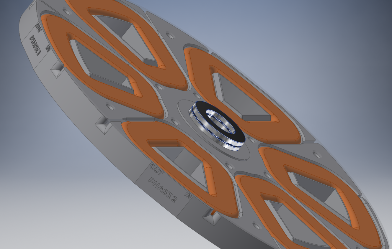
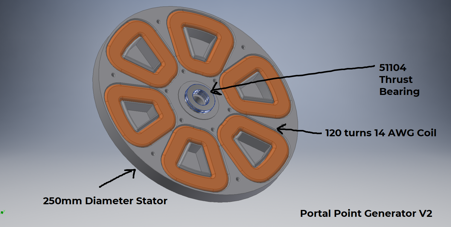
    Its time to go big or go home. Portal Point V2 is going to be a 500W generator, while still trying to be compact enough to fit on a commercially available 3D printer.  I'm still using the same 40x20x10 N52 grade magnets, but increasing size of the coils. 
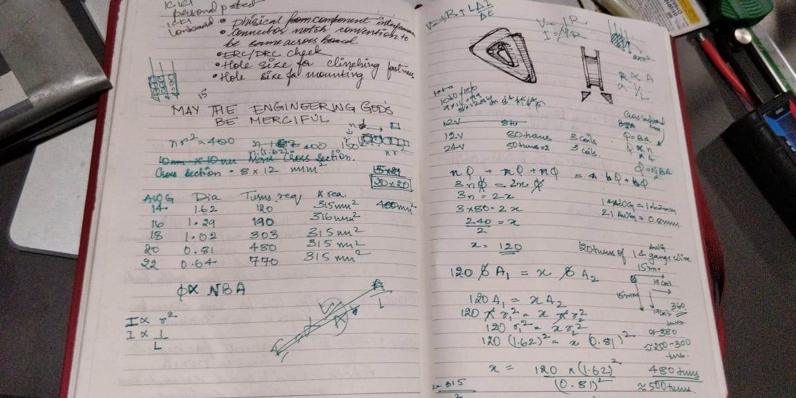
    According to my ( very dirty ) calculations  I need about 120 turns on 14 AWG copper, to keep resistive losses at a minimum. Ill explain the calculations later, but I'm working on the following assumptions to end up atleast at a 500W 12V generator:

    1) Another 3 phase generator, that uses 3 coils instead of 2 per phase claimed 800W 12V using 14 AWG wire of 80 turns. it used slightly larger 52 grade magnets

    2) To determine the optimum packing,  area of the coil etc, I approximated the of the wire to be a square  of side equal to the diameter, so i have a size I can start CAD modelling with.  I didn't no any other calculations other than that with this approximation

    With that, I came down to a coil of 120 Turns, and a stator of diameter 250mm which can house 2 coils per phase.

    I decided to use a couple of thrust bearings to keep the distance between the rotor and stator constant, that differ from the previous design that can to be fastened to the drive shaft to maintain proper clearance. It was a pain to assemble. 

    I'm looking at DFA as a side goal for this version. 

    I labeled the coils as well, so i'm sure of the wiring.

  • From Asia to Antarctica : Worlds first 3D Printed wind turbine in Antarctica

    Vijay10/03/2018 at 05:59 0 comments

    I was lucky enough to get documented as a part of the efforts of a film crew during the expedition to Antarctica,  with others who have made fighting climate change their life's mission.  I come up somewhere towards the end, but the entire short documentary is  worth the watch beginning to end. 

  • Generator Optimization

    Vijay08/23/2018 at 13:27 0 comments

    With the one version done and tested,  I wanted to address and fix some of the design and construction issues I faced while building and designing version one. The following are the list of changes I am aiming for:

    1) Rotor Assembly

    Assembling the rotor was literally a bloody nightmare resulting in cuts and bruises from shattered magnets flying all over the place.  The rotor will be modified to aid easier assembly

    2) Stator rigidity

    Owing to the weight of the stater assembly with the large number of magnets, the stater began to show signs of fatigue after a few days of continuous use ( When kept in vertical position). A large amount of weight from the heavy rotors were being concentrated at the center of the stator. I will be beefing up the stator with ribs, and redesigning the casing such that it takes away the loading from the stator as much as possible. 

    3) Coil Winding Rig

    A coil winding rig with a arduino and encoder which can repeatably reproduce the number of coils on the stator winding's

    4) Using a Wind Turbine Charge Controller 

    I had used a buck converter with a bridge rectifier initially which did the job of charging a phone, but I think its not the best way to do things. For one, there is no over-speed protection which shunts the output of the turbine to prevent it spinning wildly out of control in case of a storm or something.  Image result for wind turbine charge controller

    So I ordered this relatively cheap wind turbine charge controller. I'm still unsure what wizardry is going on inside it, but hope it does a better job than a buck regulator. 

  • Voltage Output

    Vijay08/06/2018 at 06:33 0 comments

    I peaked the voltage output at about 75V with a drilling machine before I screwed up my multi-meter, probably by going over its rated current, but it was producing a cool 24V from a ceiling fan.
    I was able to step down the voltage using a buck regulator and charge things, but think I would need to Charge Controller of sorts to better regulate the voltages and give a decent amount of current, especially if the voltages peaks go above 40V which would damage the buck converter. 

  • Rotors

    Vijay07/15/2018 at 15:43 0 comments

    The picture below shows of the rotor stacks up into an assembly. The magnets get embedded into the magnet housing, and is covered by a laser cut sheet metal cover. The sheet metal cover prevents magnetic flux of the powerful magnets from going out of the generator, and also makes the flux stronger on one side of the Magnets.

    The rotor brace prevents the powerful magnets from collapsing into each other ( THE MAGNETS ARE FREGGIN POWERFUL), as well as provides a way to mount the drive shaft. Use M3x16 CSK screws to mount everything together.


  • Star Topology Arrangement​

    Vijay07/15/2018 at 15:34 0 comments

    Connect the phases in a delta pattern. There are 2 Coils for each phase. The coil on the opposite sides are of a single phase.

    Connection coils of the same phase in series first, the "OUT" of the first coil with the "IN" of the second coil of the same phase.

    The above picture shows 9 coils, but its connected the similar way for 6 coils as well

    Then connect all the remaining "IN"s of the three phases together which would be the common ground. All the "OUT"s will be the three phase output.

    In the below images, I covered the coils with the stater cover, and marked the IN's and OUT's of the coils to aid wiring.

    Figure 24: Twisting joints of wire pairings (as per description)

    removed the enamel from the ends of the wires with sand paper:

    Figure 21: Stripping enamel off the copper wire with the help of sand paper

    (My desk is messy, i know)

    here im' soldering two coils of the same phase together. 
    Figure 23: Soldering pairings of copper wires

  • Stator Assembly

    Vijay07/14/2018 at 11:23 0 comments

    Coil Placement:

    Place the coils inside the Coil Holder/ Stator. There are three pins inside which the coils will sit.

    The "IN" and "OUT" of the coils where the winding started and ended need to the placed in the appropriate notches. These will help identify how the coils would be wound.

    Figure 15: Coils placed in coil housing

    Coil Housing Preparation:

    Glue gun the coils in place.

    Figure 16: Glue applied to raised edges of the coil housingApply glue to the edges of the coil housingFigure 18: Coil housing being coveredThe coil housing is covered with the 3DP Housing CoverFigure 19: Coil housing being covered

  • Assembly Process: Jig Preparation + Coiling

    Vijay07/13/2018 at 13:59 0 comments

    Jig Preparation:

    The winding jig is used to wind the coil. The Jig and the Jig holder are fastened together using M3 fasteners.

    Figure 1: Both jigs affixed together along their shape and their elevations facing each otherPrint 2 Jigs,  fix them along their shape, and elevations facing each other.

    Figure 2: Jig handle attached to the jigs on one faceAttach the 3DP Jig Holder on one of the faces. I recommend marking this face, and you should use the same convention when winding all the coils., and the winding direction should match. 

    Figure 3: Jig handle attached to the jigs on one faceFasten everything togehter

    Figure 4: Wire inserted through hole in the jig to help the wire sit in the grooveThere is a small hole in the jig through which you can slot the wire, to keep it in place while winding.  Put the 30 AWG wire into this from the inside of the jig, coming out.

    Figure 5: Attach kapton tape to the face of each edge in a reverse manner to help get the coil out of the grooveAttach kapton tape in the 3 slots . Once the coiling is done, the kapton will be folded onto the finished coil to hold its shape.

    Coil Preparation:

    The jig is mounted on a power screw driver/drilling machine using a HEX bit. There is a notch on the jig to indicate when the maximum number of coils are reached.

    Try and maintain a constant level of tension on the coils to get a roughly same number of coils. 6 coils will need to me made like this.

    Use kapton tape to keep the cool from unwinding. Keep the kapton in place on the inside of the coil, and wind on top of it.

    There is a hole on the jig where the start of the coil is placed. As long as you use the same convention for winding, and placing into the coil holder, you should be alright, only the polarity of the DC would change.

    To Do: Automate this process with a encoder and counter to be more accurate.

    Figure 7: Wire being wound around the jig with the help of a hand drill and drill bit

     If you have the patience, you can hold the handle and wind by hand, or use a drill/power driver to make this faster. You need 6 coils.

    Figure 8: Unscrewing the jig handle

    Fold the Kapton tape over the coil to hold it in place. Now work backwards to remove the coil.

    Figure 9: Removing the jig handle

View all 11 project logs

  • 1
    Generator V1: Coil Jig Preparation

    Jig Preparation:

    The winding jig is used to wind the coil. The Jig and the Jig holder are fastened together using M3 fasteners.

    Attach the 3DP Jig Holder on one of the faces. I recommend marking this face, and you should use the same convention when winding all the coils., and the winding direction should match. 

    There is a small hole in the jig through which you can slot the wire, to keep it in place while winding.  Put the 30 AWG wire into this from the inside of the jig, coming out.

    Attach kapton tape in the 3 slots . Once the coiling is done, the kapton will be folded onto the finished coil to hold its shape.

  • 2
    Generator V1: Coil Preparation

    Coil Preparation:

    The jig is mounted on a power screw driver/drilling machine using a HEX bit. There is a notch on the jig to indicate when the maximum number of coils are reached.

    Try and maintain a constant level of tension on the coils to get a roughly same number of coils. 6 coils will need to me made like this.

    Use kapton tape to keep the cool from unwinding. Keep the kapton in place on the inside of the coil, and wind on top of it.

    There is a hole on the jig where the start of the coil is placed. As long as you use the same convention for winding, and placing into the coil holder, you should be alright, only the polarity of the DC would change.

  • 3
    Generator V1: Removing coil from Jig

    Fold the Kapton tape over the coil to hold it in place. Now work backwards to remove the coil.

View all 7 instructions

Enjoy this project?

Share

Discussions

Cecil Victor wrote 02/22/2019 at 09:37 point

Hey vijay, first off, being from Tamilnadu myself, I am really proud of what you have achieved with this project. If you dont mind me saying, you are living the engineer's dream (congrats!). I have been wanting to build a generator for a while now, purchased a CR-10s recently and I am overwhelmed by the world of 3d printing and its infinite possibilities. I always wanted to explore the scope of 3d printed parts in real world industrial applications but your project has proven that and has given enough motivation to build my own. I have a couple of questions 

1. I know that carbon fiber filaments are lot stronger than the regular PLA. How did you print each of these parts ? 100 % infill, 0.2mm layer height ? I know that setting up the prints also play a part in how strong the finished part is. 

2. Does the filament hold up well (melting) against heat generated from the coils. ?

3. Since i am pretty much going to be your design as the inspiration in building my own generator, any advice on the do's and dont's. Thanks !!

  Are you sure? yes | no

Vijay wrote 06/22/2019 at 09:09 point

PLA does well, but then again, i was in Antarctica :p
If you are going for outdoor application, i would recommend going got PETG, or CF-PETG. 

I used a 0.8mm nozzle, so my layer to layer bonding would be much stronger and i was able to get away with 2 shells and 30% infill. You will probably need to double that if you are doing 0.4mm nozzle. 

Only advice: get your calculations right, and careful with the magnets!

  Are you sure? yes | no

Sixunderground wrote 11/30/2018 at 23:48 point

Hey Vijay, really like the project.  I am having a hard time finding the magnets that you used in that size (and V2), can you post a link to where you purchase them ?

  Are you sure? yes | no

Mike Fair wrote 11/30/2018 at 18:01 point

Have you considered allowing the jigs to be wound and mounted directly without removing the coils? Leaving some leads for wiring up, then simply "snap" the coils into their proper positions, and then screw down the leads?  It seems much easier to mass produce winding and assembling that way...

  Are you sure? yes | no

SwiftyTheFox001 wrote 10/22/2018 at 10:49 point

Hi! Your project has motivated me to reactivate my own wind turbine project that I ditched because of the lack of a proper generator. 

Two questions though regarding your new design: 

1) why did you drop the 3 coils per phase in favour of the 2 coils? The more coils in series, the higher the output voltage at the same power. Higher currents are to avoid because of the coil losses (I^2*R) - so a third coil is less painful than a higher current. 

2) I personally go for a wave wound stator which is mechanically more complex, but has some electrical advantages over your chosen winding method. Did you do any trials with these?

Anyhow, I totally agree with the bigger diameter. The more diameter, the higher the radial velocity, the higher the delta phi / delta t (=Voltage)

Please post also some test results from your test bench in the future. I miss these always in other generator projects. ;)

Br

  Are you sure? yes | no

Vijay wrote 10/22/2018 at 13:27 point

Hi Swifty, thanks for your comment!

For the V1 turbine, which I had to take with me to Antarctica, I had limitations because of the size of the 3D printer I had at the time. Also the 40x20x10 Neodynium magnets were getting pretty heavy, and I had a weight limitation on the expedition. I would have to use 24 for 3 coils per phase instead of 16 for 2 per phase. 

I now have a larger printer, but decided to go for a higher gauge (14AWG) instead of 3 coils per phase for lesser resistance. instead of stepping down the voltage that I had to do in V1, I wanted to design it such that it would give me 12-14V without any losses because of the voltage/current conversion.

I hope to be able to get at-least 500W with the new design, which should be possible seeing other generator designs

When it comes to the configuration of the stator, I would love to hear your inputs. I'm very new to generator's, and my experience is mainly in mechanical and CAD design.

  Are you sure? yes | no

SwiftyTheFox001 wrote 10/22/2018 at 14:54 point

Larger printers help a lot. :)

Regarding the windings, I can give you a youtube video of someone who knows what he does (not from me, and turn down the volume...): https://www.youtube.com/watch?v=53GIT3c0M3M 

You can also use two smaller wire gauges in parallel to get less resistance that you wind at the same time . It also helps a bit to increase the amount of windings for the same cross section.

But, please go on with your version, I'd like to see the outcome! As I said, I am in the middle of the development process myself.

  Are you sure? yes | no

Vijay wrote 10/27/2018 at 14:10 point

Ill try these different combinations and see how it effects the output. Thanks for sharing! 

Keep me posted if you come across anything else useful. 

  Are you sure? yes | no

Adarsha wrote 08/09/2018 at 13:10 point

Very cool project Vijay. Wondering how the magnets are oriented? entire face of the rotor are all of same side (so one face is south pole and other is north pole)? or inside each rotor you will have balanced number of S and N poles?

  Are you sure? yes | no

Vijay wrote 08/11/2018 at 06:16 point

On each rotor face, N and S alternate, which get coupled to the opposite  pole on the other rotor.  There is a metal disk on the outer face of the rotors to prevent magnetic flux getting lost outside the motor and concentrates it inside and between the rotors only.
The magnetic forces are so strong, its impossible to get the rotors apart without tools once they are on the shaft, even with a significant gap in between.  
God save the person that would have got them stuck together :p

  Are you sure? yes | no

TJ wrote 08/02/2018 at 01:11 point

I think there is a STL missing from the posted files. It seems to be listed as "Stator Brace/Shaft Clamp". Is it possible to make this available with the other files? Thanks in advance Love the project.

  Are you sure? yes | no

Vijay wrote 08/11/2018 at 06:06 point

Sure let me check this out.  I was planning on doing a once-over with the prints and designs and make sure everything is proper, I had to do some amount of filing and sliding to get everything to fit and not scrape parts inside the generator for this version, so I imagine it may be a little frustrating for people. 

  Are you sure? yes | no

Vijay wrote 08/11/2018 at 06:33 point

I've added Generator.rar to the files, it has the full assembly. 

  Are you sure? yes | no

Jeff Cooper wrote 07/31/2018 at 20:37 point

Thanks for sharing your project.  This should definitely spur some 3DP green energy projects as well as be a great teaching instrument.  Did you record the numbers of turns in the individual coils?  Thanks again!

  Are you sure? yes | no

Vijay wrote 08/11/2018 at 06:11 point

Almost everything was empirically determined. I chose the N52 grade magnets first, which were available locally, and just designed everything around that, right to the maximum number of coils that would fit. 
I plan to make a coil winding machine with an encoder and arduino to recreate this project in a more systematic manner than flying by the seat of my pants. 

You are very welcome!

  Are you sure? yes | no

Tinkerloonllc wrote 07/15/2018 at 17:08 point

I love this!

  Are you sure? yes | no

Carlos wrote 07/12/2018 at 00:04 point

Amazing. I can definitely use this on disaster relief deployments.

  Are you sure? yes | no

Vijay wrote 07/15/2018 at 15:57 point

I hope it comes of use to you!

  Are you sure? yes | no

Dennis wrote 07/11/2018 at 18:29 point

You had better weather in Portal Point than I did!

  Are you sure? yes | no

Earl Baugh wrote 07/11/2018 at 17:38 point

Are you going to make the plans available for others to print?

  Are you sure? yes | no

Vijay wrote 07/13/2018 at 10:52 point

They are up now,  will update process and procedure by today.

  Are you sure? yes | no

Aayush Khanna wrote 07/11/2018 at 17:08 point

Pretty cool stuff ! 

  Are you sure? yes | no

Vijay wrote 07/15/2018 at 15:57 point

Thankyou!

  Are you sure? yes | no

Shah Selbe wrote 07/11/2018 at 17:02 point

Awesome project! I can see us using this in the field.

  Are you sure? yes | no

Vijay wrote 07/15/2018 at 15:57 point

Thankyou! I hope the design comes of use to you!

  Are you sure? yes | no

Mike Szczys wrote 07/09/2018 at 21:18 point

A very cool build, and amazing that you tested it out in Antarctica, wow!

  Are you sure? yes | no

Vijay wrote 07/16/2018 at 06:44 point

Thankyou Mike!

  Are you sure? yes | no

Similar Projects

Does this project spark your interest?

Become a member to follow this project and never miss any updates