I didn’t include one in the original design but with the current setup I now have the ability to quantify the EMI footprint. Spoiler alert: I’ve concluded one isn’t needed. Here’s why.
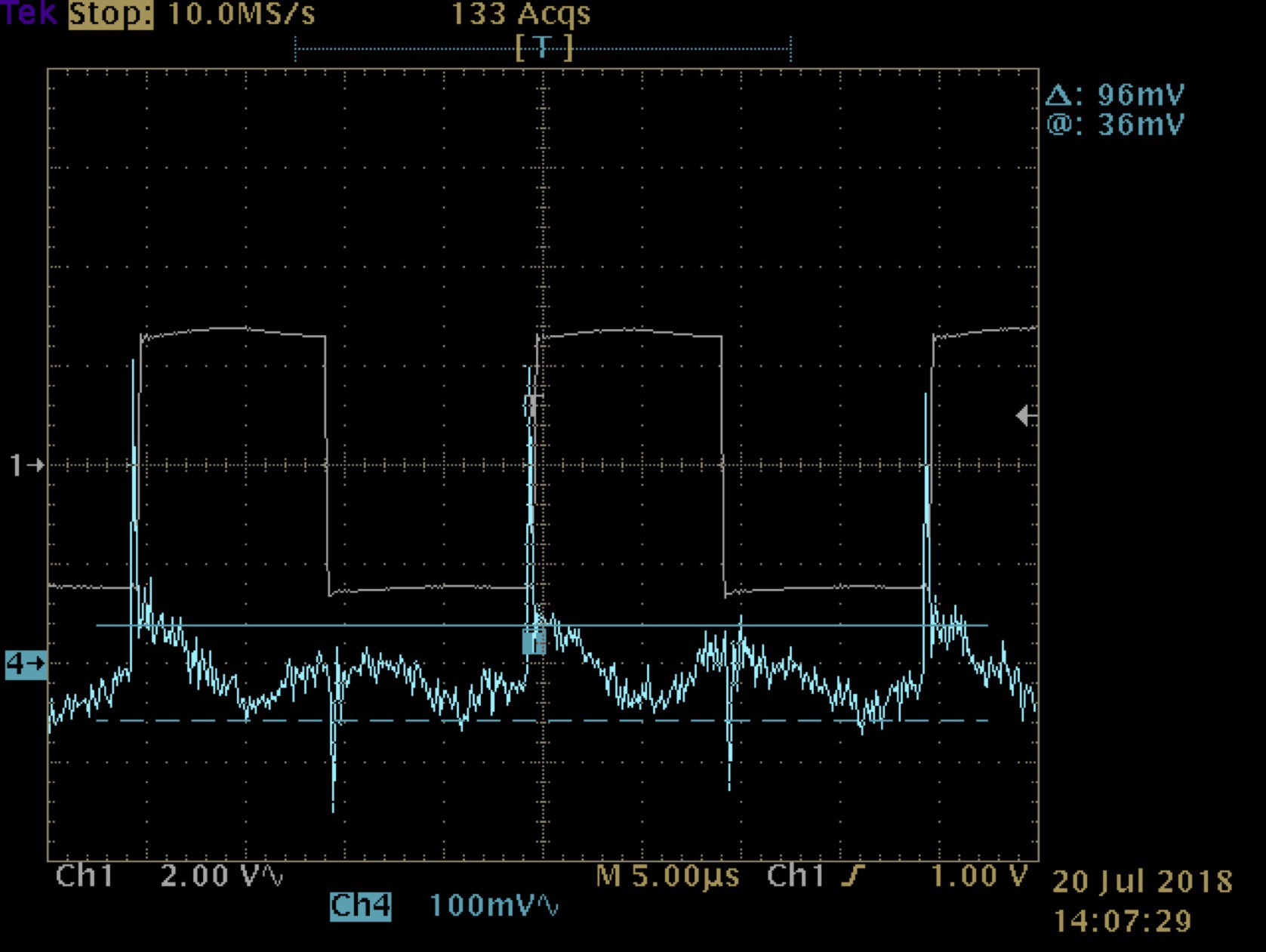
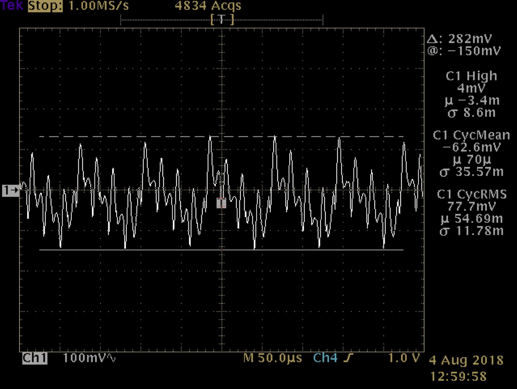
With a 350W load the voltage ripple across the power source (a battery) is ~ 100mV P-P. With a 400W output the current ripple is 3.56A P-P. Why the discrepancy in loads? These are the measurements I had on-hand and was too lazy to go back & redo. Besides, they favor a worst case. Here are the waveforms, voltage & current respectively.
The required inductance for the filter can be calculated with the formula: L=(Vr/Ir)TonToffT where Ton & Toff are time on & off in percent and T is the period in seconds. Substituting:
L = (0.1 / 3.56) x 0.95 x 0.05 x 1e-5
L = 13nH
Hardly worth it. Note that this is with power leads measuring about 2 ft (66cm) each. In a real-world application the power leads will likely be longer and even if they are paralleled or twisted will present a similar or larger inductance. It also assumes a low impedance power source which is a necessity for this thing to operate correctly. Using the above figures: R = V/I = 12 / 3.56 = 28mΩ. Assuming a 12V supply: 12 / 0.028 = 427A. That’s probably a bit high for a 9Ah battery but even at half of that its impedance is only 56mΩ.
While on the subject of input filters I’m not looking at common mode. This board has a lot of EMI coming from the sine section with much of it due to poor layout. Also the transformer doesn’t incorporate faraday screens so this will be left to evaluation in the revised build.
Discussions
Become a Hackaday.io Member
Create an account to leave a comment. Already have an account? Log In.