 Nicolò
To add the GSM / GPRS I opted for the SIM800C chip (The one witch castelled mounting holes) , it is small and does not cost much and it sends SMS. It could also call, but when I designed this module, I still did not know where I was going with the project.
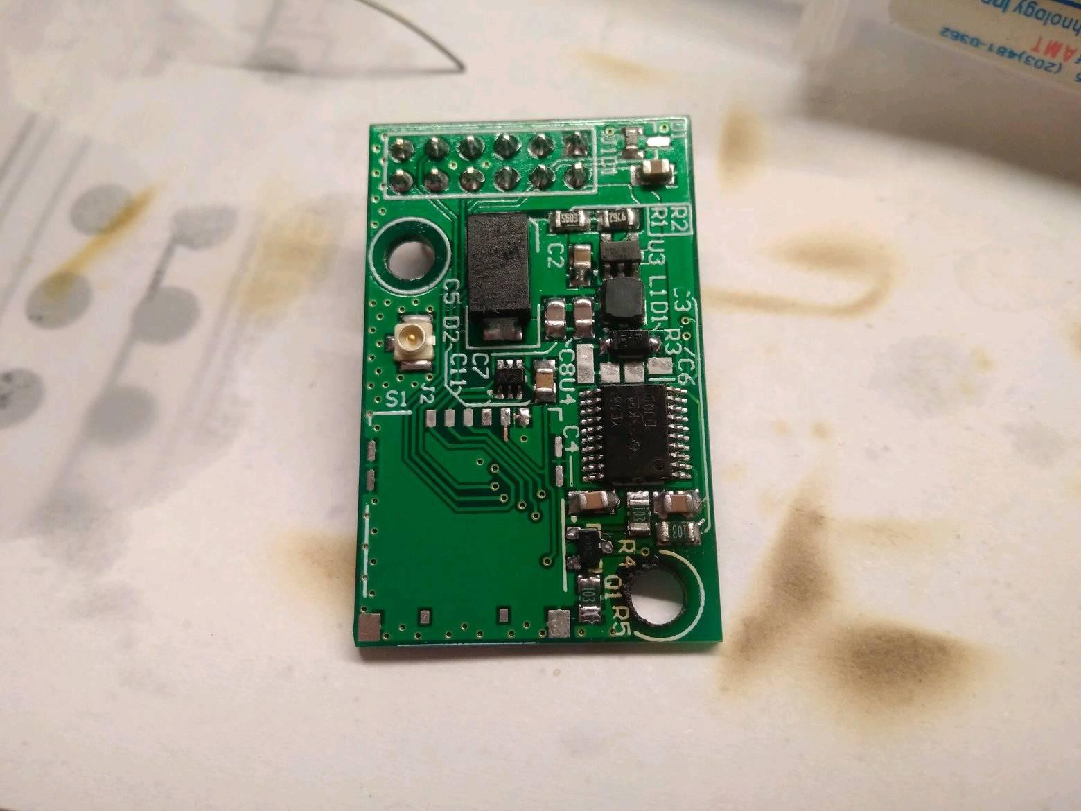
First of all it should be said that a regulator is integrated in the SoC used inside these modules (it is designed for battery-powered cellphone). The module must therefore be powered at a voltage of 4V. Could not they make everything simpler? Having 5V from the switcing power supply I would have a fall of around one volt. Chinese manufacturers use diodes (with poor success), so I have opted for a switching regulator.
For the purpose I choosed a TI TLV62569, small footprint (The board is 35mmX24mm) and needs few external components.
Having never used a regulator of this type (I am self-taught) I read multiple times the datasheet, some things unfortunately I wasn't abe to understand properly. Despite this I made the circuit, the fact that the module in transmission can use up to 2A still worries me. (I don't have a load tester)
Using the documentation found online I started doing the schematic for the SIM, a condenser here, one there for the bypass, one zener, and the ESD protection diodes for the SIM.
The development seemed to spin smooth, but at some point, I was reading the "UART Communication" section of the hardware design of the SIM800: The I/O is at a voltage lower than 3.3V, damn!
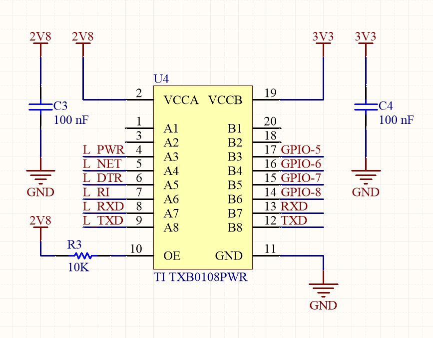
I then started looking through the components drawers to see if I still had logical translators of an old project ... fortunately I still had many. This is the TI TXB0108PWR. (I had used these for the same purpose in my project of the car controlled via the internet. The model had an ArduIMU board with sensors and worked at 5V and the raspberry instead has a 3.3V IO.)
This is commonly used for the same needs I have so I decided to use that on my design. And here is where the nightmare started: Back on by RCWeb Car i had similar problems but I solved it by buing chips from a official distributor instead of ebay. But this time it don't worlk even if I use the "original" chip. The schematic looks ok to me. There are the two bypass caps on the voltage rail A and B, the enable pull-up resistor but for some odd reason if I apply a square wave on one side this is not present on the other.
I tried to load that pin using a resistor divider but also in that case I got a stuck HI output on a voltage level different from both sides A or B. I also tried with pull-up and pull-down resistor and tried to measure the values on the other side but if I change the logic state the "output" is locked on a mid value below the side A supply rail. This happens also on the reverse. I think that this have something to do with the auto detect direction system that the chip have.
Unfotunatly after two days of attempt I'm not able to make this IC working. If you have suggestions you'r welcome to join the discussion!
Discussions
Become a Hackaday.io Member
Create an account to leave a comment. Already have an account? Log In.
The SIM800 Expansion board is a new expansion board for the SIM800. It allows the SIM800 to be used as a server in a network. The expansion board is designed to be used with the SIM800 and can be connected to it via USB. I need to read https://www.pwmania.com/how-to-combine-wrestling-classes-and-coursework-writing-without-any-loss-of-performance article now to do extra activities without hurting my education.
Are you sure? yes | no