Although I have ordered PCBs several months ago, they have only been delivered this week!
I have no idea how they managed to pack together all this stuff. I had to split it up into 3 different boxes after opening the package!
The boards quality looks good to me!
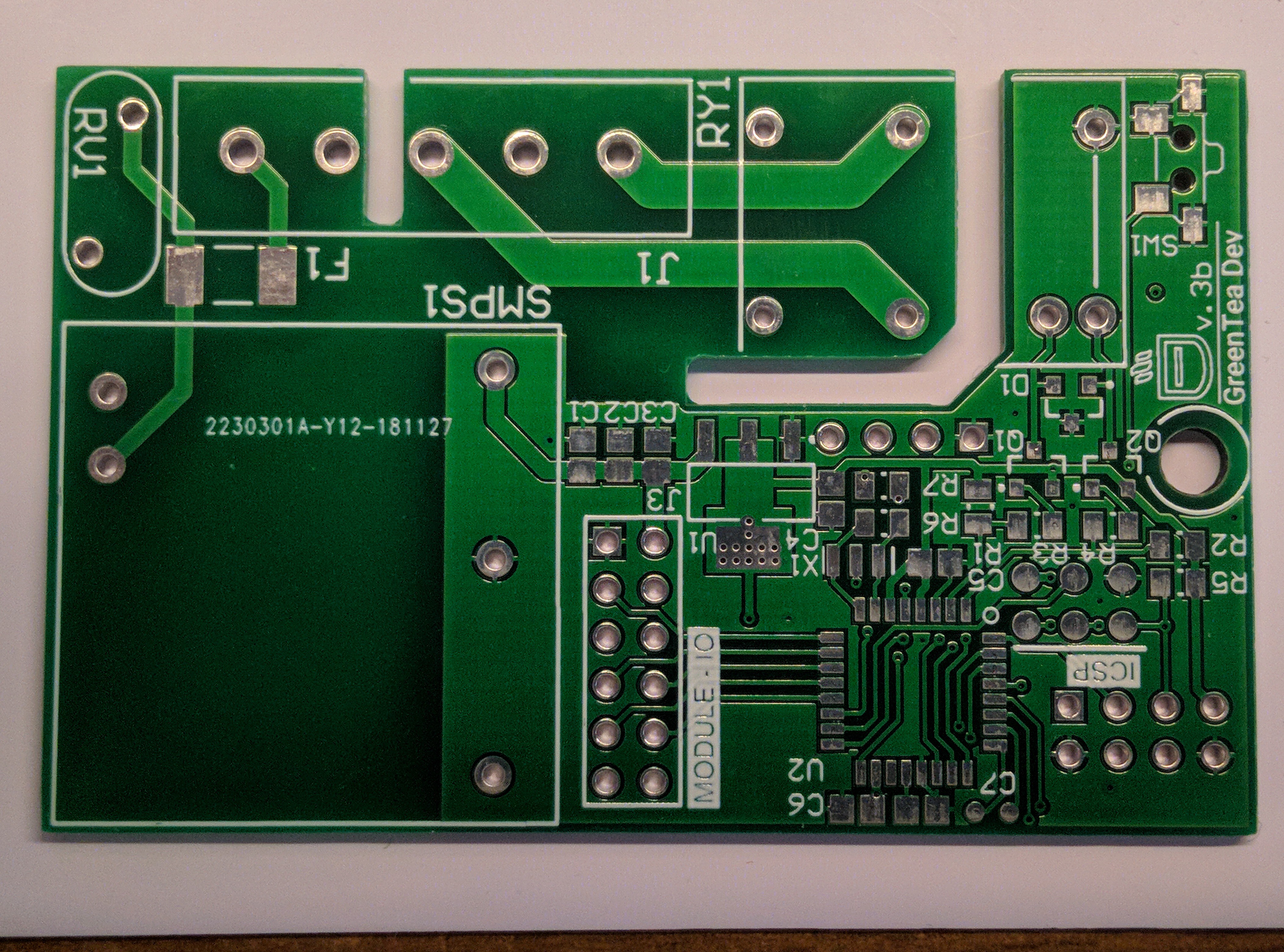
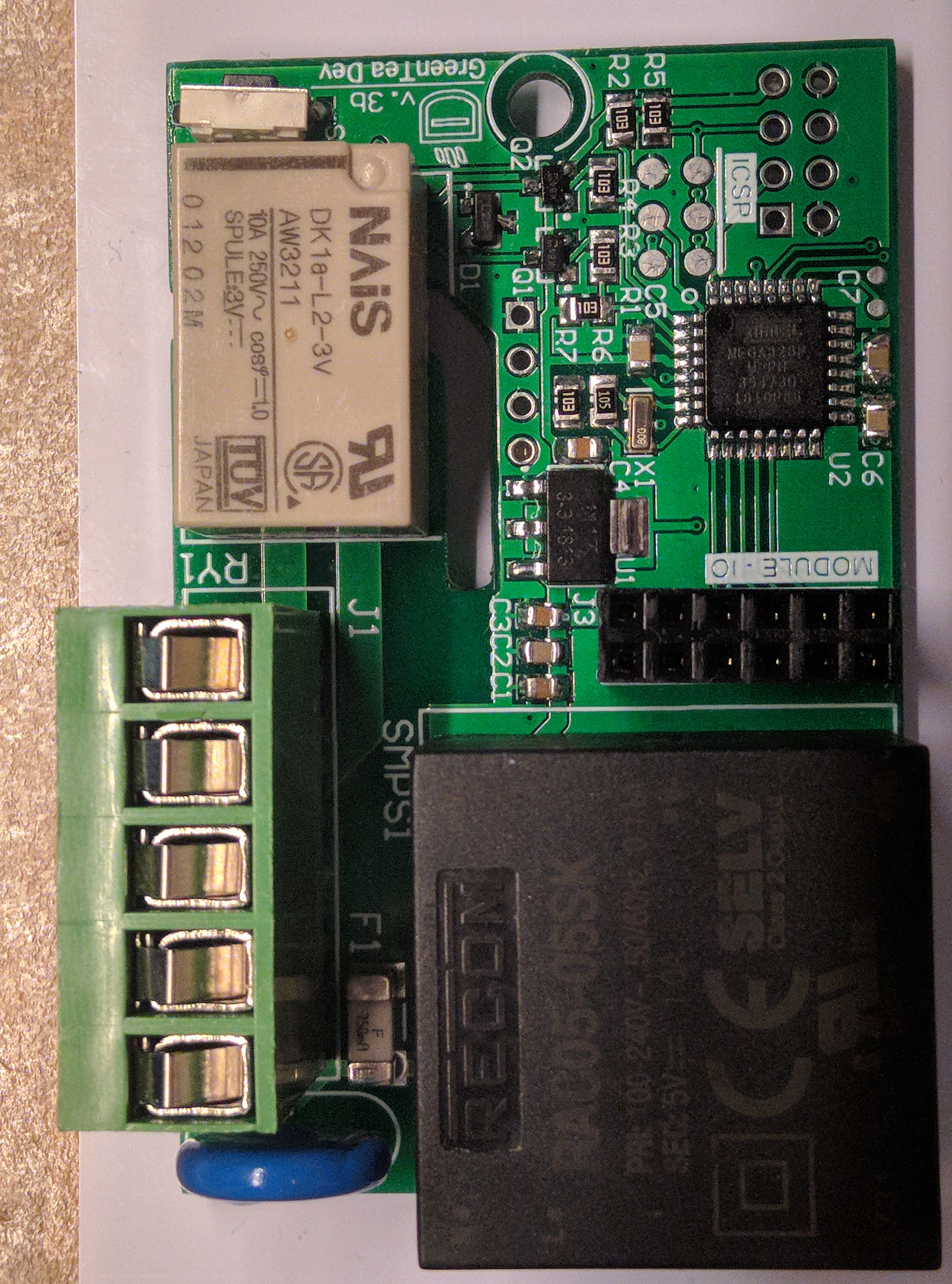
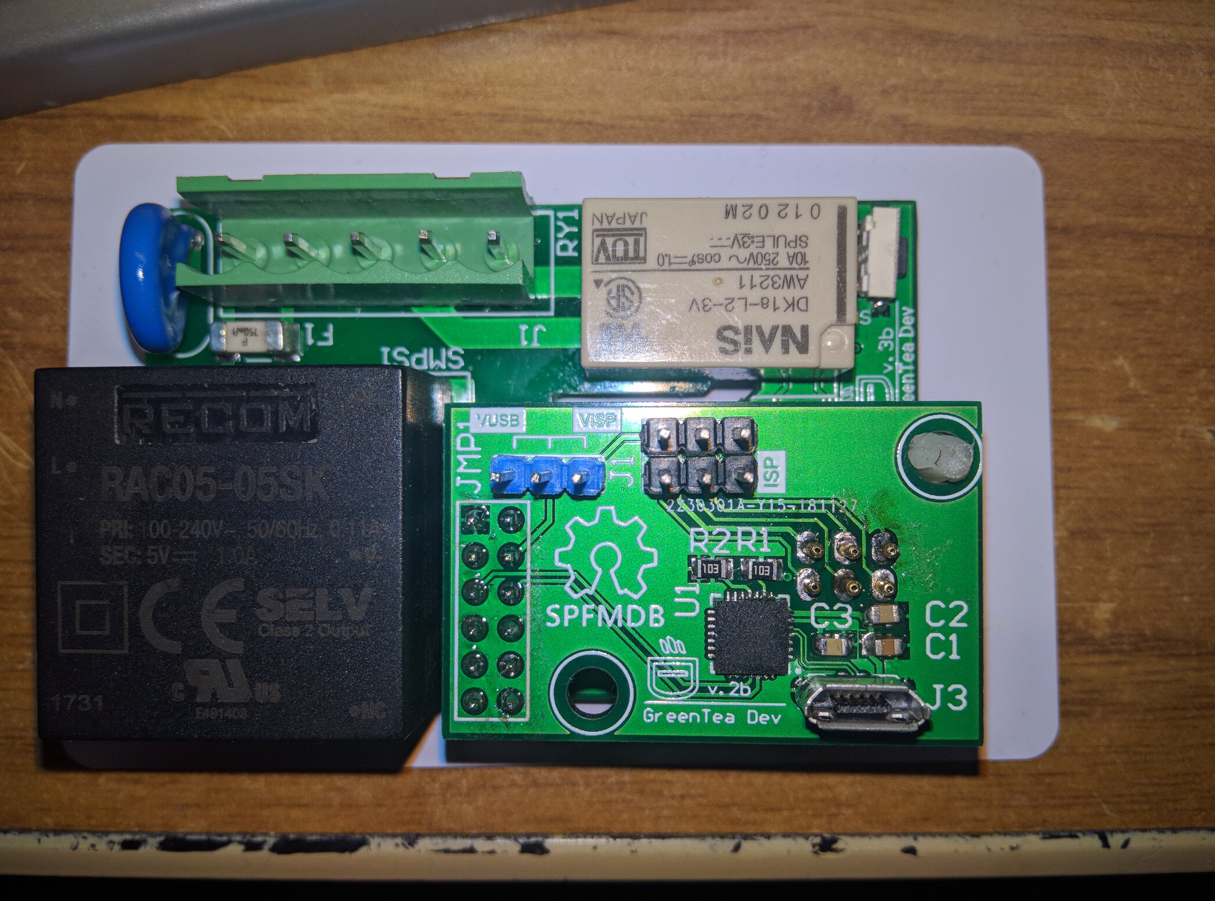
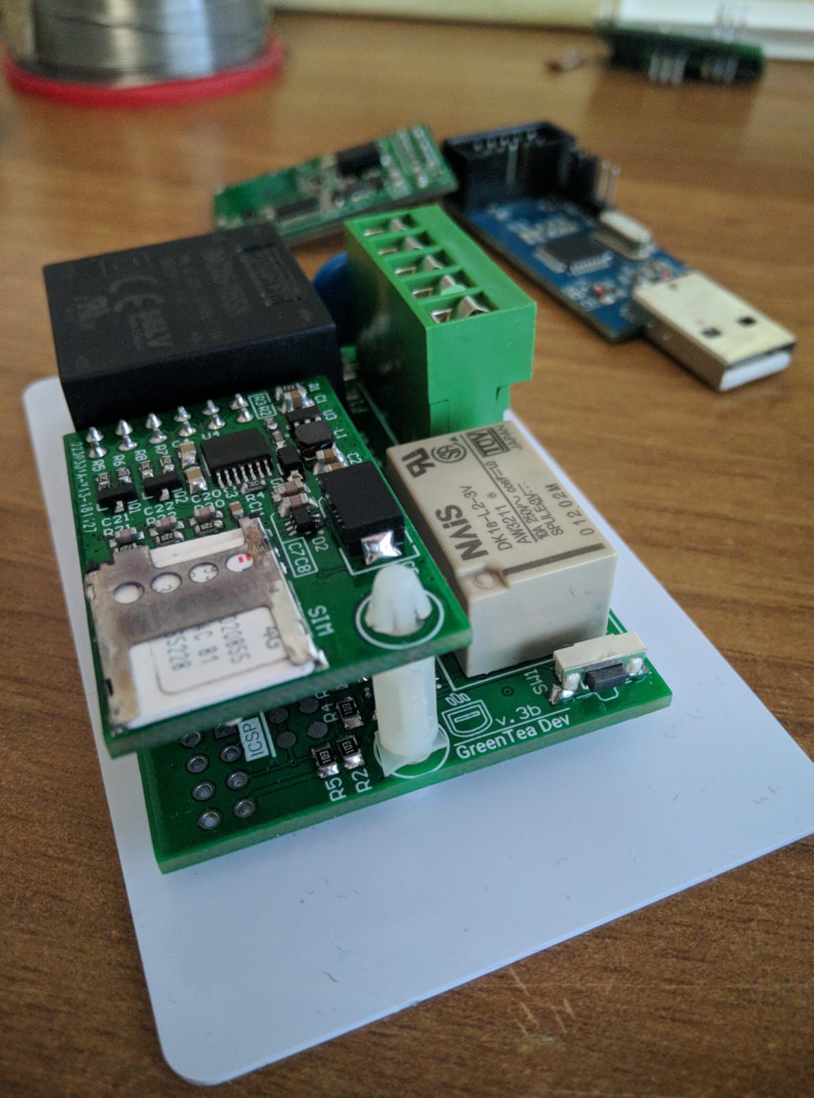
So I proceeded to assemble the Baseboard, everything went smoothly. The Phoenix connector fits perfectly, I had to move some connectors but in this way I got:
The shorter board of 1 mm
SMD components all from one side
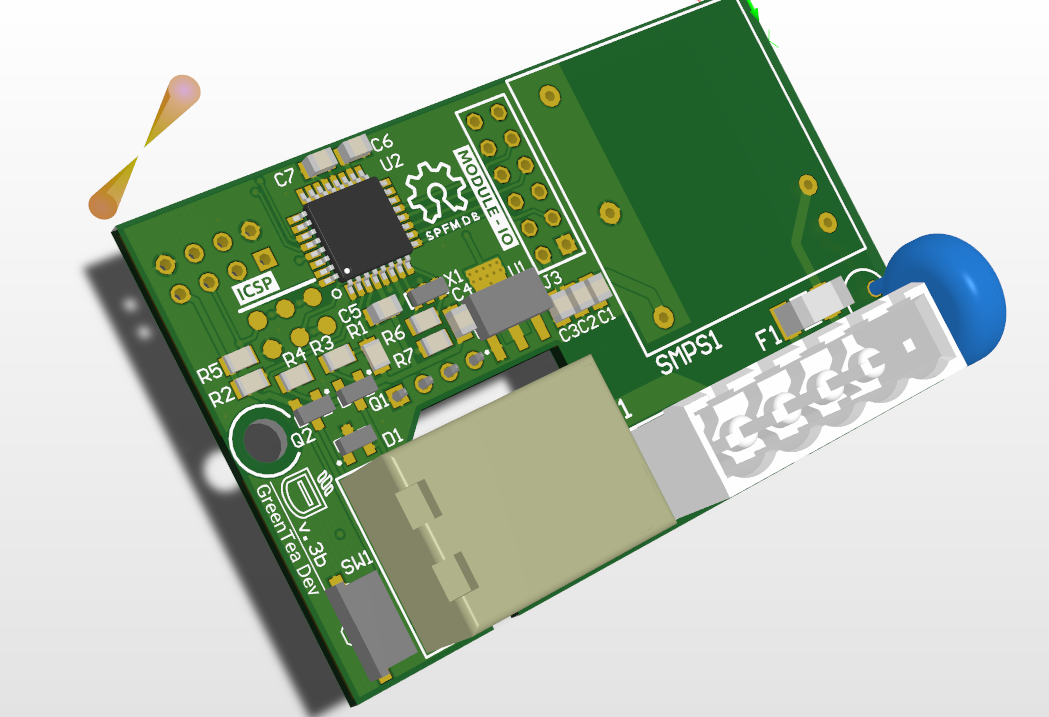
As already mentioned, reducing the size has also caused some boredom on other boards. One of these is the programming card.
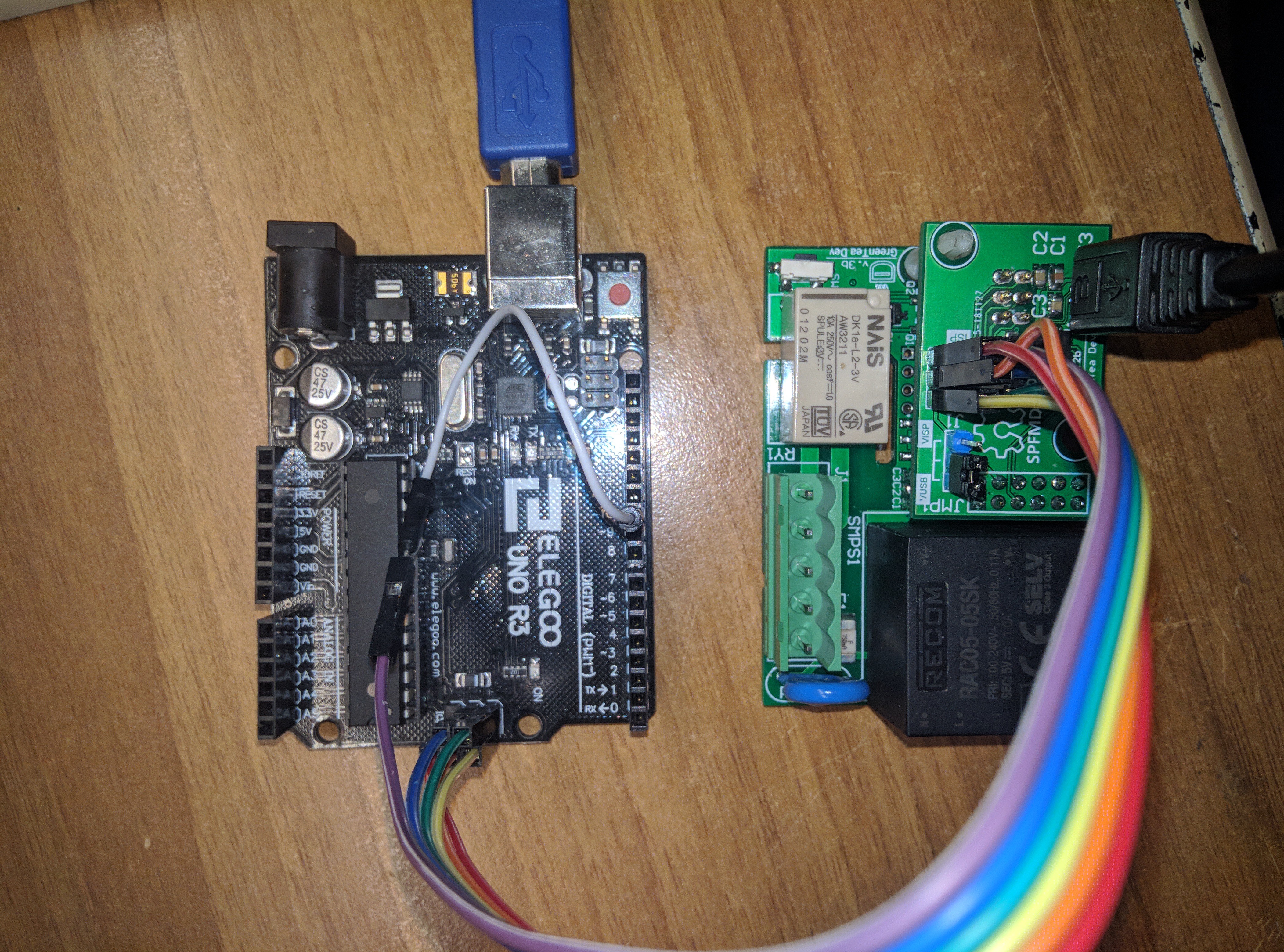
The latter has been updated to have a USB / Serial adapter so as to reprogram the Atmega 328p on the fly.
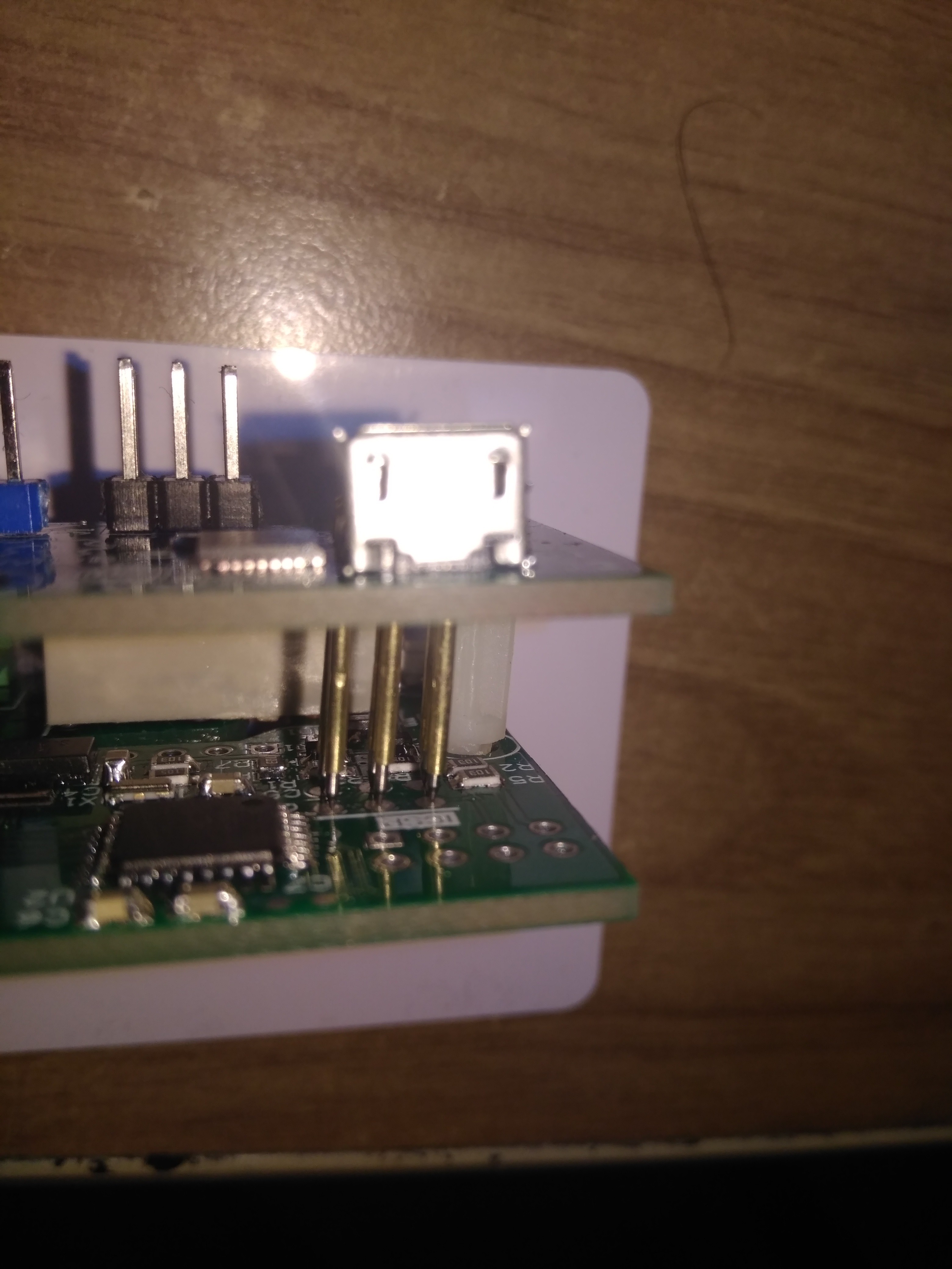
In addition to serial programming, the programming module has pogo-pins to write the bootloader to the MCU.
The board works perfectly, pity for a small mistake: I have not moved the pogo pin pads after resizing the baseboard, this translates into having the pins diagonally. (The important thing is that it works)
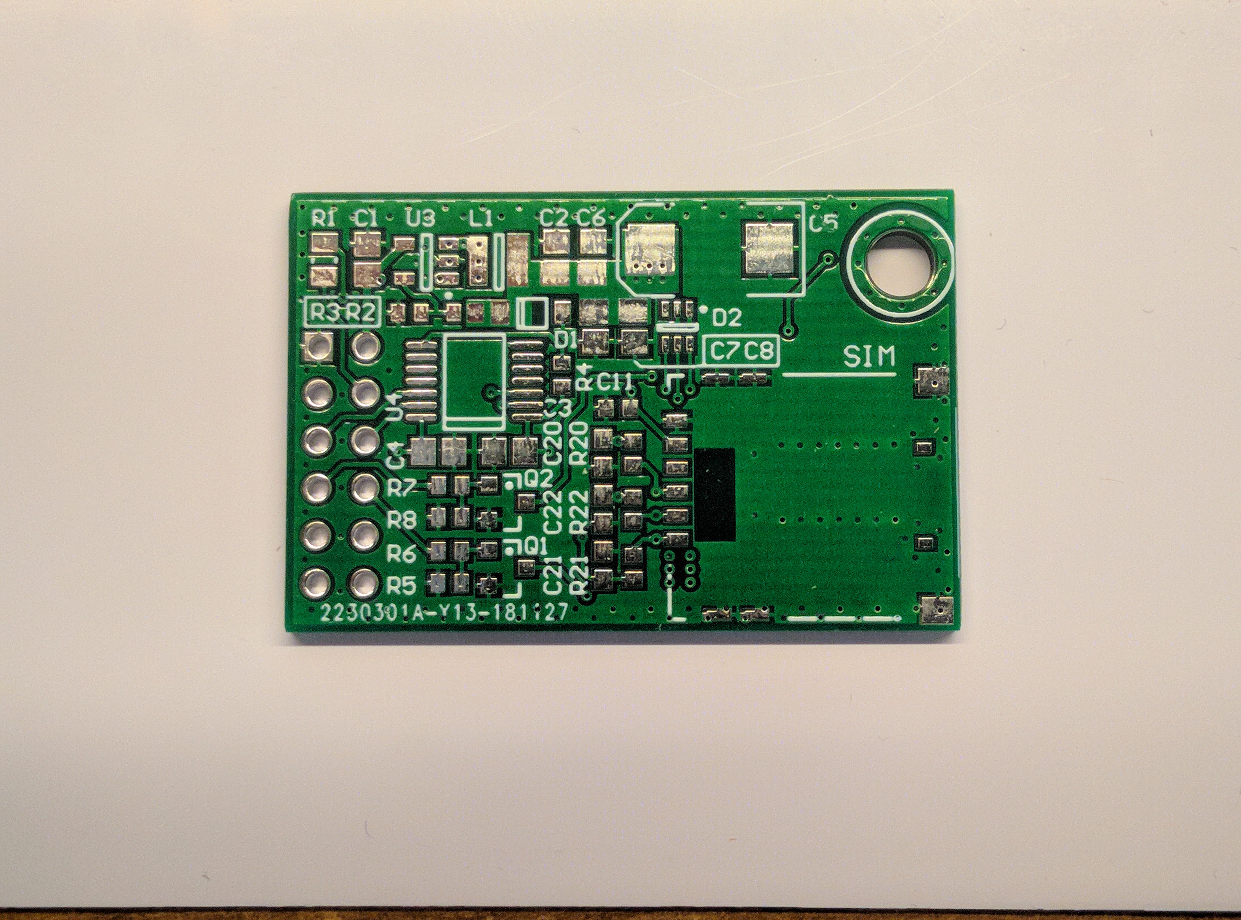
NB-IOT, the module is assembled, AT commands the SIM7020 module responds correctly but I can not connect to a network. I'm looking for information at local TLC to understand if I need a particular sim.
The board itself with the SIM800C should work perfectly! (I have not yet been able to assemble one)
Unfortunately due to the various holidays all shipments are delayed and I could not make a new prototype in time to end this 2018 with a working board.
But I made some progress with the Atmega 328 firmware. I can read and write on the slave UART. For now no interrupt only polling.
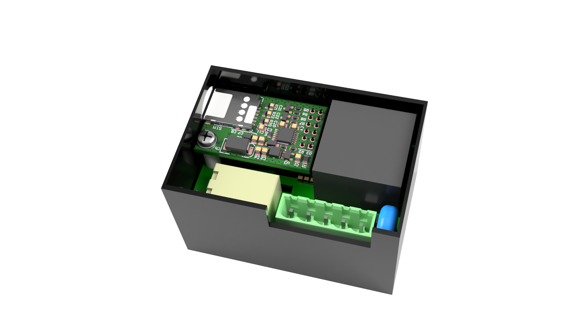
Some time ago I changed the size of the boards because I had noticed that the thickness of the electronics box was too thin. Not being able to change the size of the box I opted to edit the one of the pcbs.
Only one millimeter in width has caused quite a few problems. (Shield redesign and I had to move components around on baseboard) My poor skills in the parametric cad did not help, after altering the parameters the model was "broken". I thus proceeded to start from scratch.
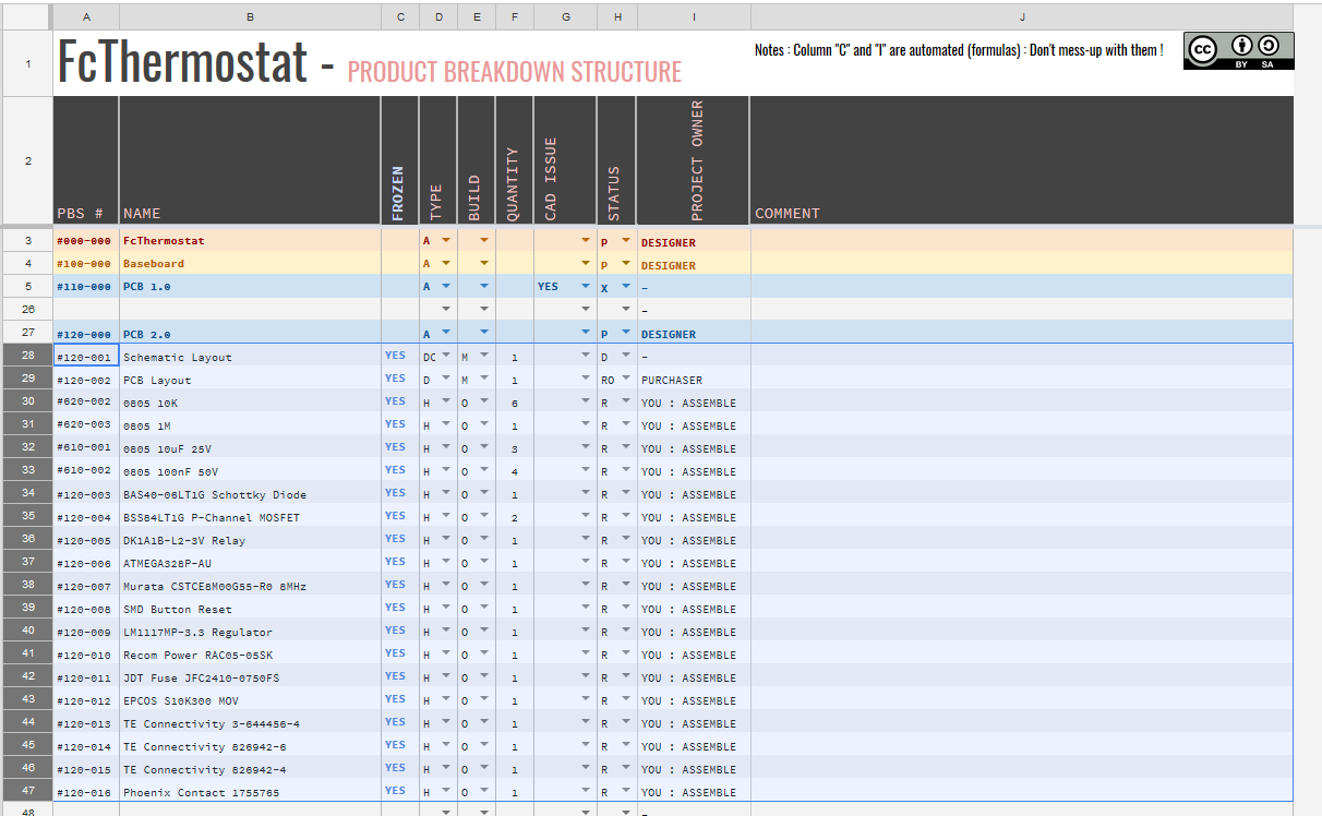
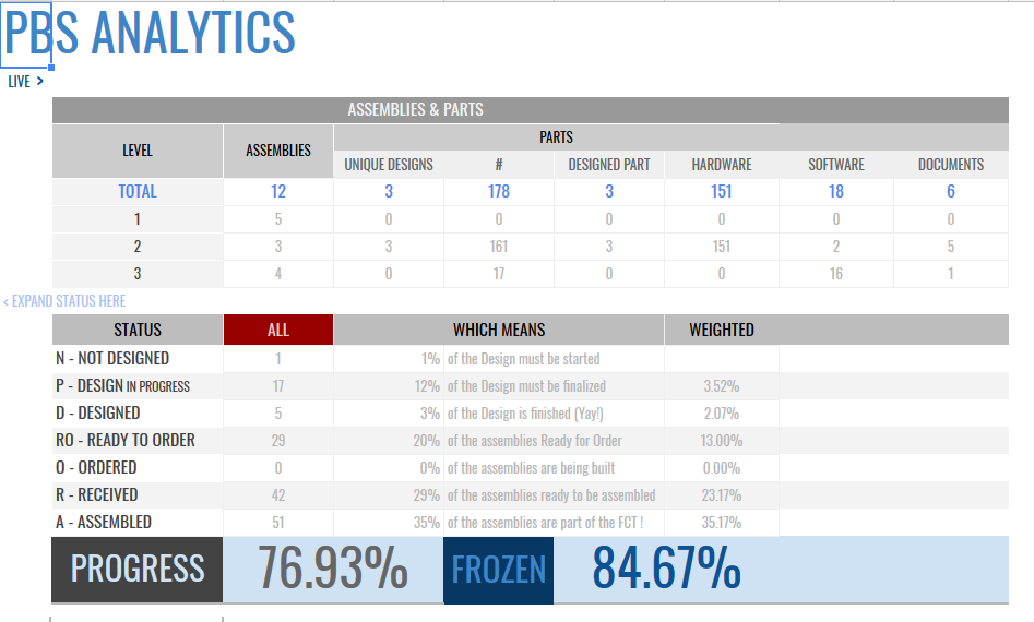
Adoring the music and having taste for particular machines I discovered the MMX project (in reality, I have been following the project for a long time), the author of this project has recently made available a spreadsheet to create a PBS.
I then entered all the information of my project into a new sheet based on the one published by Martin and taking advantage of the features now I can easily see what there is and there is no need to do!
WOW 76% Hah I still have to add all the info about the front board!
Taking advantage of the 11.11 sales, I have bought some new parts for the project, at this moment I'm compiling the BOM to then order the new PCBs.
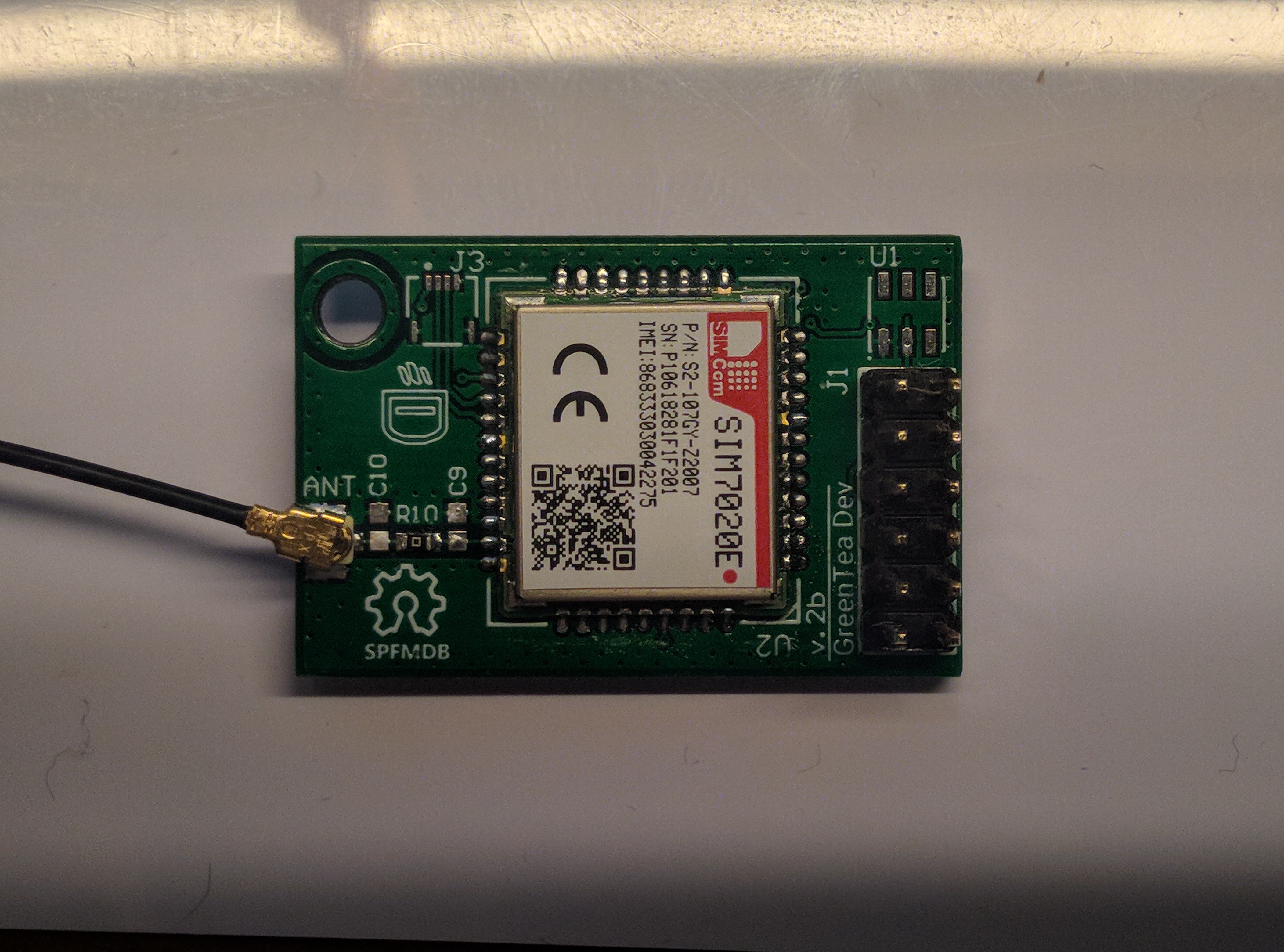
Say "HI" to the SIM7020, Raúl Luna first suggestion was to use an LTE modem, although in Italy the GSM network is still active and will still be due to some very old infrastructures, I decided to try this module.
It should be compatible 1:1 with the old SIM800C (So I don't have to redesign the board again!), maybe the AT commands will be different, I'll have to find out as soon as I get the module!
The development of the firmware continues, now it is possible to read and write the 1Wire EEPROM through the slave processor.
I still have difficulty implementing interrupts for the Serial, and reading from serial. Perhaps this time I complicated the project too much!
Hi, as you may have noticed from the title of this thread I'm working on creating my own SBC. You will wonder why this crazy idea, when the market is full of these products. Unfortunately all the products already present in the market are "huge" compared to the dimensions that I need to respect. (Some are just a couple of mm off )... Initiallyct my project was meant to use the SOM "C.H.I.P. Pro" but, as many will know, they went bankrupt.
I do not need a lot of processing power, the only fiew requirements are:
No SD card for boot, but eMMC or Nand
I2C bus
SPI buses to drive a Display (at least one, the second could be using gpio bit-banging)
Analog or Digital Audio. (If analog I need a microphone input)
The need to have at least one armv7 due to some closed source libraries that I will have to use.
Fiew GPIOs
Wireless connectivity
I started looking at other SBCs in the market, many had only the SD, or a NOR SPI.
Initially I wanted to use a MIPS chip (like a mediatek MT7688 or MT7628) for convenience and available choices... but mother Google did not allow me because of its proprietary library.
I kept looking. By now disappointed by the solutions I started to print some SoC product briefs. I am an open source lover and for this reason I opted for Allwinner. (Despite the poor collaboration of the company the sunxi community has done a really good job on porting the drivers to mainline linux and datasheets are avilable for free). I started reading the datasheet for my selected chip the R16 or the A33 and with a little patience I started to realize the wiring diagram. (I used a already made board to understand some stuff the datasheet provided/found on the net sucks at describing what some pins does/works). Time passed and I was still deciding which interfaces to use, how much RAM and so on. Then I discovered the Neutis N5 module, they were doing what I had started. I remember that I was happy, just a few weeks left to release the board. Suddenly the date was moved, it kept changing month after month. Fed up I decided to resume the project of my SBC.
Being a hobbyist I have always used Circuit Maker to make my PCBs, I have never had to use more complex software. (Before I used Eagle but Autodesk licensing ruined it). The project continued, and using a reference board similar to the one I wanted to realize I started to position the components, to create the nets and everything else. It's been less than two years since I started. From the initial project I had to make several changes: the most important was that manufacturers have discontinued the 8Gb RAM DDR3 chip, now there is a scarcity of 100nF capacitors and who knows what else will come out.
The Neutis N5 module is almost close to release (if they don't keep changing the shipping date) and so I no longer need to continue making this SBC. Al the work I did was done by a hobbyist, I'm not an electronic engineer, no one taught me how to make these boards. I used the informations available on the internet to document me. My SBC will not see the light of sun, because the production cost of that PCB is close to 2k with assembly and parts).
Today I'm stuck because of this Front board that is still a concept, and the fact that the Neutis module continues to delaydoes not bode me well.
I'm testing out the firmware for the baseboard. Right now I have basic UART bridge (I have only tested the TX from Master to Slave) and the IO Expander functions. Interrupts are not implemented yet. I'm working on PinChangeInterrupts for the IO Expander.
This is part of the sketch of the master:
#include <Wire.h>
voidsetup(){
Wire.begin();
Wire.beginTransmission(42); // Transmit to device #42
Wire.write(0x02); // Write to the port direction register
Wire.write(0xF0); // Register data
Wire.endTransmission(); // Stop transmitting
delay(500); // Some delay to make is easy to see on the logic analyzer
Wire.beginTransmission(42); // Transmit to device #42
Wire.write(0x07); // Write to the TX buffer register
Wire.write("HELLO!\n"); // Register data
Wire.endTransmission(); // Stop transmitting
}
voidloop(){
bool changed = false;
uint8_tbyte_t = 0;
unsignedlong currentMillis = millis();
// See "Examples > Blink without delay" to understand how this workif (currentMillis - red_millis >= red_int) {
red_millis = currentMillis;
// Instead of writing the pin we toggle a bit on the register
bitWrite(byte_t, 1, !state_red);
state_red = !state_red;
changed = true;
}
if (changed) {
Wire.beginTransmission(42); // Transmit to device #42
Wire.write(0x04); // Port status register
Wire.write(byte_t); // Port data
Wire.endTransmission(); // Stop transmitting
}
}
As I have already said, Atmega allows communication with the various modules installed on the baseboard.
The functions of the chip are:
IO Expander
Serial bridge
1Wire Eeprom reader
My current aim is to emulate a simplified version of a pcf8574 and a MAX3107 so as to be able to easily adapt the linux drivers already present in the mainline.
While for the emulation of the PCF8574 I already have a working draft of the code (with the exception of the interrupt on the GPIO) the work for the serial bridge is more complex also because of the Arduino core.
In the last period I'm working on the functionality of serial bridge. I'm working on both the code and the documentation. I then decided to uplaod a draft of my registers map for my serial bridge.
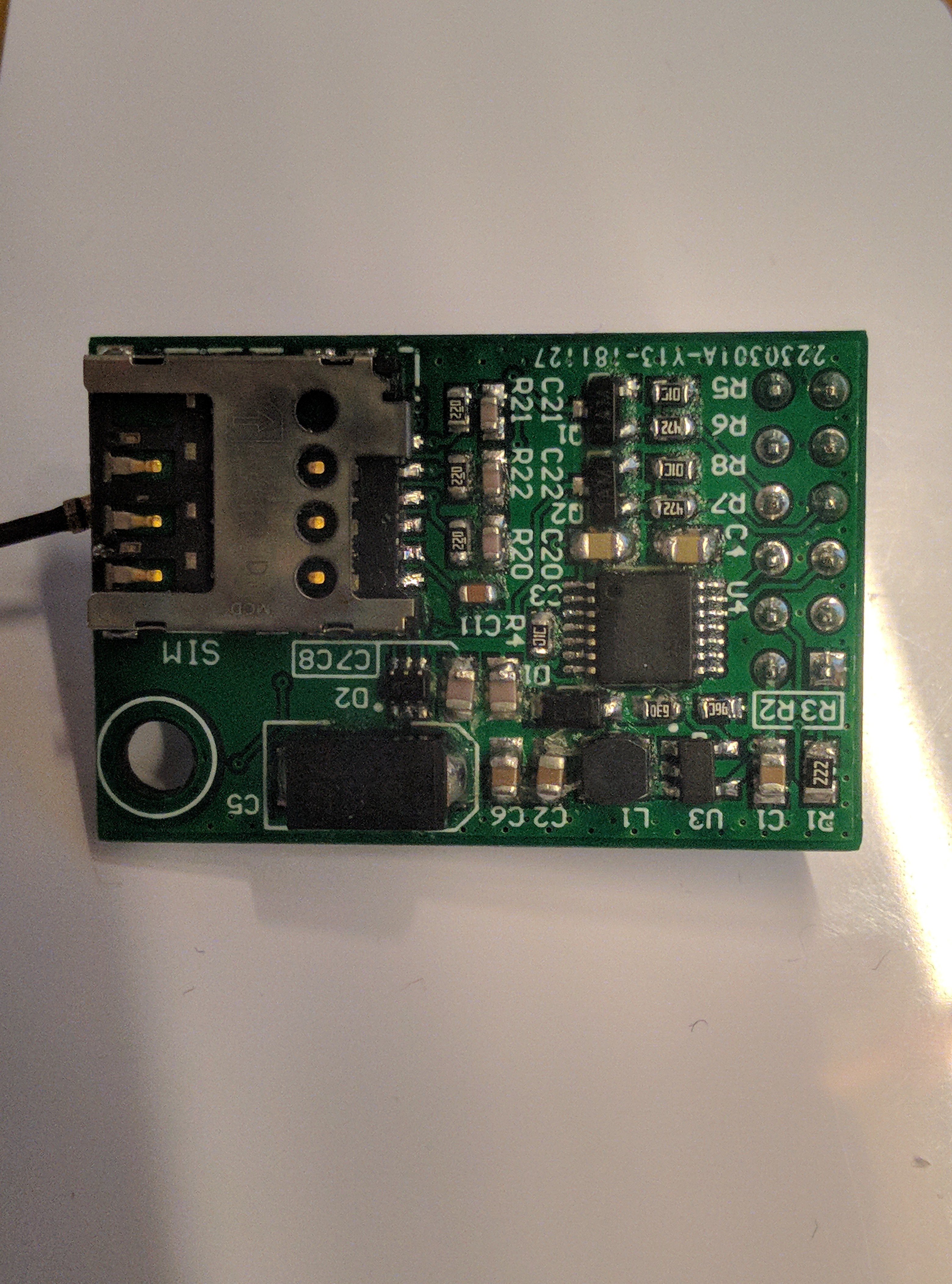
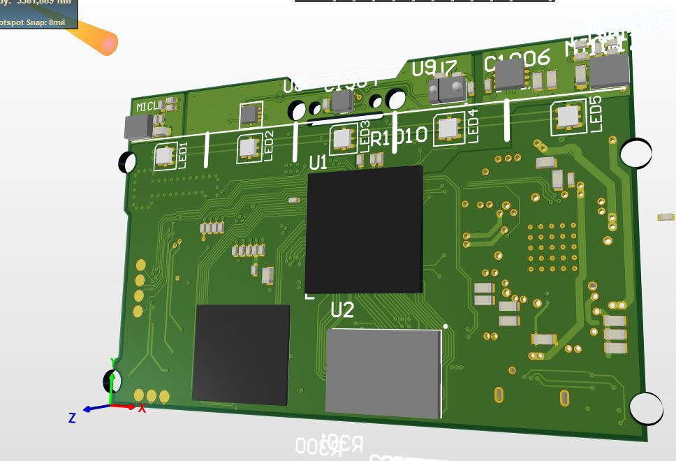
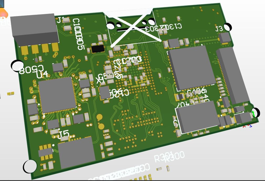
The baseboard and the programmer module has been reworked. The baseboard now have the the Atmega on the top side, one of the mout hole has been removed. In this way I have more space to route stuff on both the baseboard and on modules. The baseboard had a mirrored footprint for the SMPS, I have fixed that and in the meanwhile I rerouted the whole board! The main bg differenc of this layout that the connector of the module io now is connected to the main I2C bus in that way the front board can directly manage the shield without sending commands through the slave Atmega. The Atmega only works as a dummy IO Expander and Serial Bridge in case something need to be accesed by serial Also the programmer has been modified, now it have a built in USB to serial converter in this way I can program the Atmega with both the bootlaoder and the firmware itself. The board have a jumper to select the voltage source in this way I can use the 3V3 regulator inside the CP2102 or the one that is inside the ISP programmer. I have also reworked the SIM module, now it should work without problems. I have added more vias to shield it and with the tips from Raúl I created this layout: This one have all the necessary components for the SIM holder, and the PI network on the antenna. The big step was to replace the 0805 components with 0603. (With the exceptions of some caps in this way I can use the one I have at home). The GSM board now is a 4 Layer one, so the tracks for USB and the antenna have the right impedance!
Now the GSM moduel have also the USB routed out to a FPC connector! In this way I couldmake the front board capabel to connect to the internet instead of just sending SMS! (I still have no idea how to enable the USB on the SIM module)
Raúl Luna asked me to participate in the project, as noted, joined the team; he has a lot more experience than me in modems. He immediately offered to help me fix the GSM module I created.
I redesigned the GSM module with his advice, while Raúl (Despite the tight deadlines of his project) took a few moments to create a more updated version of the GSM module.
Also I have been quite busy and I have not had the chance to continue the project. Next step is to update the various boards and preparing a new panel to be implemented hoping not to find other mistakes!
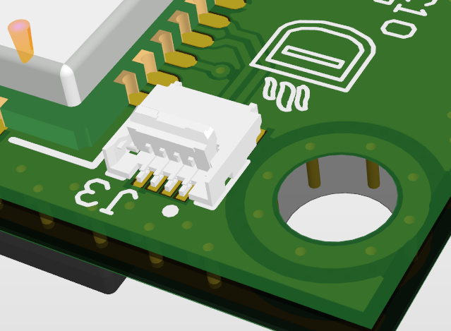
I started cheking power lines for the SIM, it wasn't fine with the multimeter. Then I checked with the scope and I got a similar resoult like this one. According to that topic I moved on to see if there was some cold joints. In fact looks like that the module is really sensible of the soldering temperature. So I cheked the circuit with the multimeter and all was looking fine. I then tested with the scope each sim tray pin. And probing the DATA pin I got a simple pulse.... like a RESET.
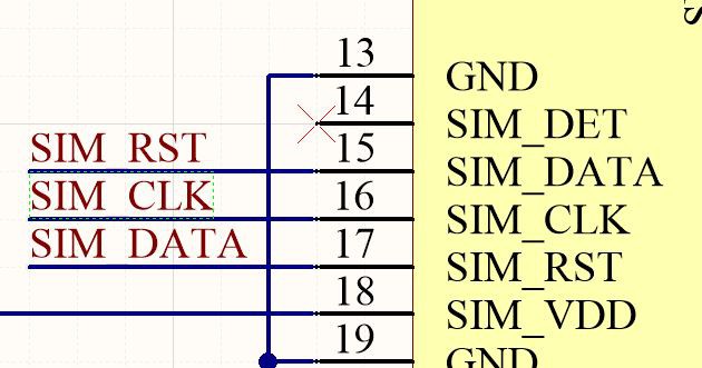
Dammit it happened again! I have no idea how this could have happened but I reversed the two signals during the shematic phase of this board. (How can I have missed that, NO ERC was coming up)
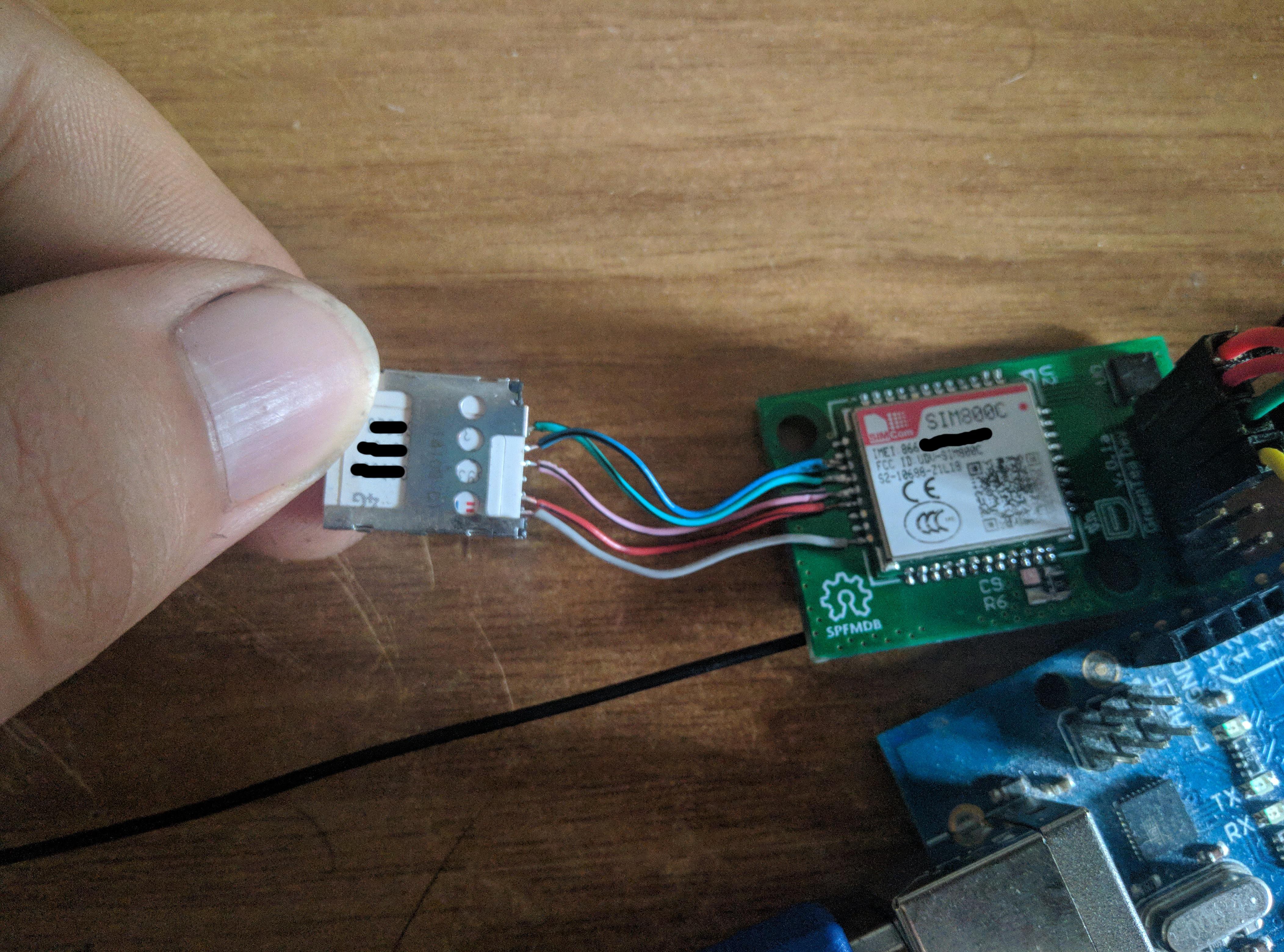
With a some patience I removed the SIM slot and soldered it with wires directly to the SIM800
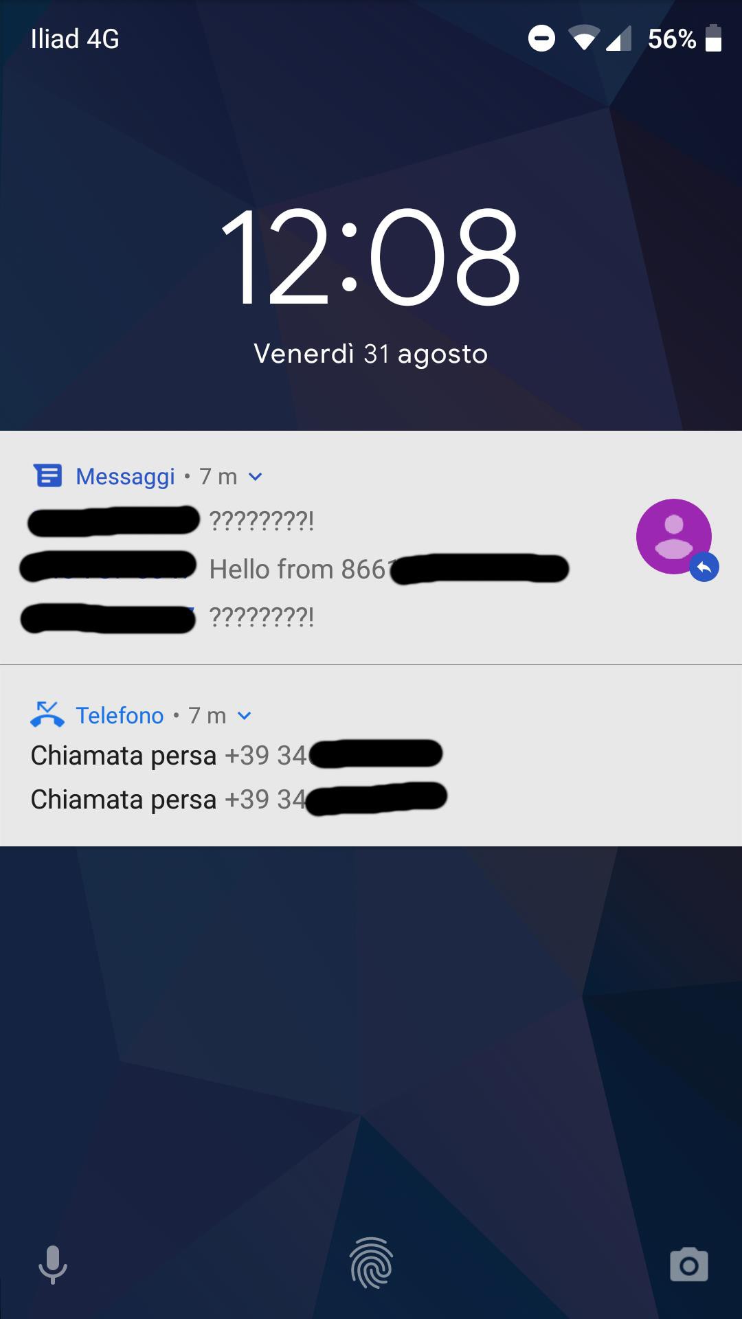
At the end I got it working, I received the test SMS and the call.
I'm still testing all the features of the module, for now I have seen that some don't works:
GSM Date & Time
GSM Location
I'm not sure if it is due to the provider or the module itself. The antenna is also working fine the AT command replayed with a -60dBm as signal value. Also without the antenna the module is able to connect to the network but with a very low signal!
 Nicolò
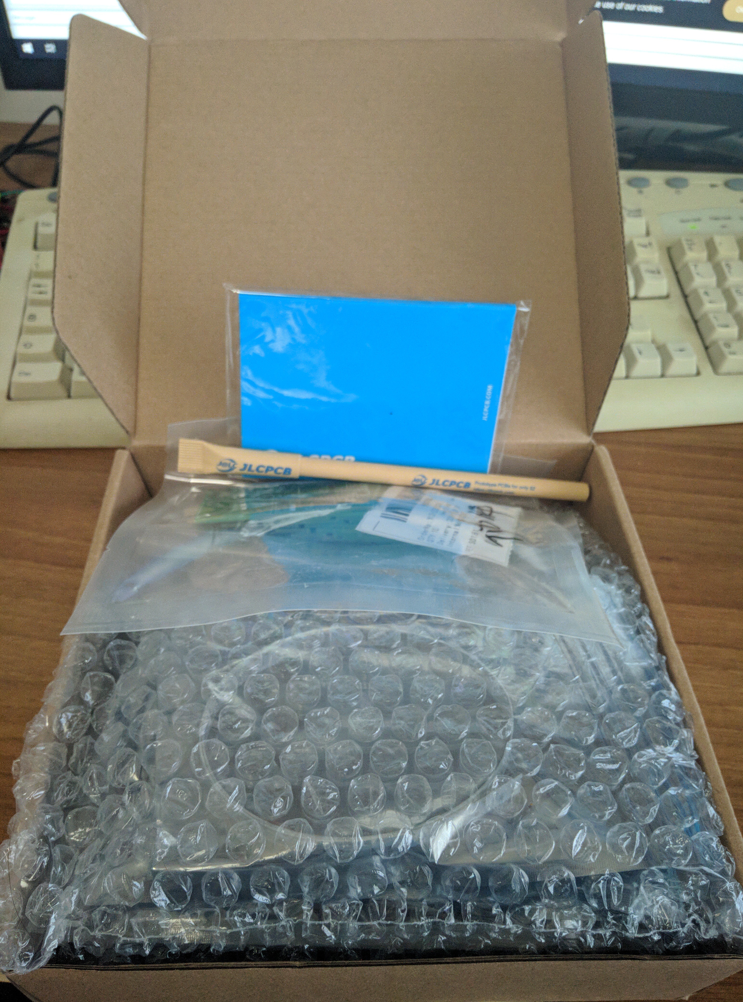

 Also the programmer has been modified, now it have a built in USB to serial converter in this way I can program the Atmega with both the bootlaoder and the firmware itself.
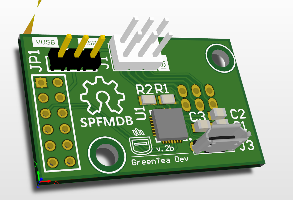 The board have a jumper to select the voltage source in this way I can use the 3V3 regulator inside the CP2102 or the one that is inside the ISP programmer.
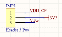 I have also reworked the SIM module, now it should work without problems. I have added more vias to shield it and with the tips from Raúl I created this layout:
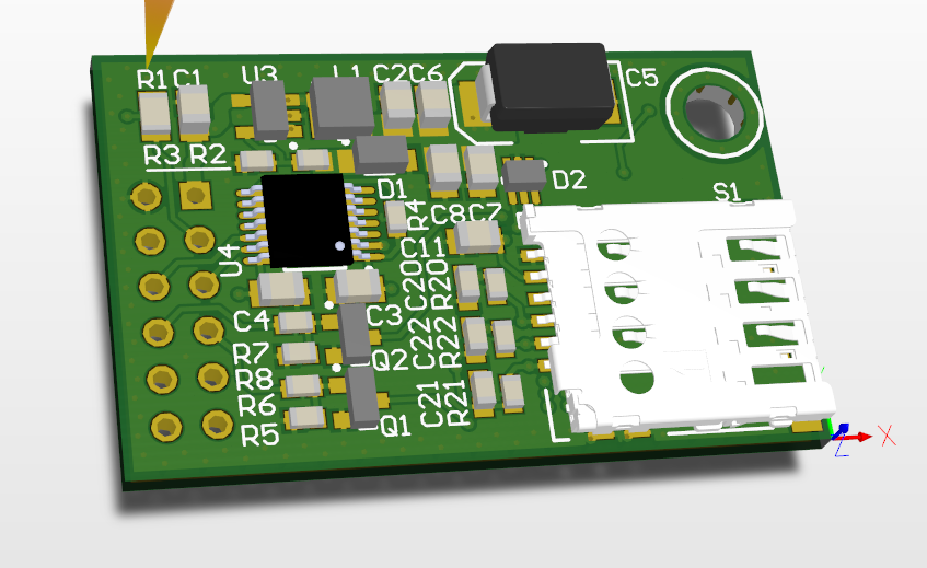 This one have all the necessary components for the SIM holder, and the PI network on the antenna. The big step was to replace the 0805 components with 0603. (With the exceptions of some