
This EMUI (ElectroMechanical User Interface) is a subproject of #YGREC8 using the advances of #Numitron Hexadecimal display module and reusing the experience of #YGREC-РЭС15-bis :-) (actually it's a 2nd version or generation of panel, after this log)
This project builds the user interface / front panel of a neovintage / electropunk 8-bits computer. It's pretty simple : diodes, buttons, switches, relays, lamps (and a few extras to interface with modern stuff). But the organisation and the ease of use are better than most computers built before the 80s.
Since no computer today uses that sort of interface, it's being designed "for educational purposes" : it's much less confusing for beginners who get easily scared by rows of buttons, since they are grouped in ways that make much more sense. Nobody would otherwise use such an interface for actual work, right ? ;-)
In this project, I explore why front panels were so cumbersome.
Of course there is the argument of cost and price. By the 70s, few people would actually toggle switches to program a computer, except those too poor to get a real computer system (or the kids undergoing training). Those miserable folks would have to
- write their code in assembly language (on paper !)
- translate their code into binary (by hand !)
- input the binary codes with switches on the front panel (without error !)
This is an error-prone procedure that would be suitable only for short sequences of code, such as a bootloader or a deadstart routine. For example, the CDC6600 had a panel of 144 switches to encode the bootstrap sequence.
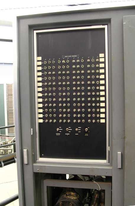
But the CDC6600 is a "high end" system (the top of the line !) that could afford the marginal expense of so many switches. Low-end, cheap, affordable computers make a lot of compromises and the user's time is a commodity. Save a hundred switches and let the user do the work !
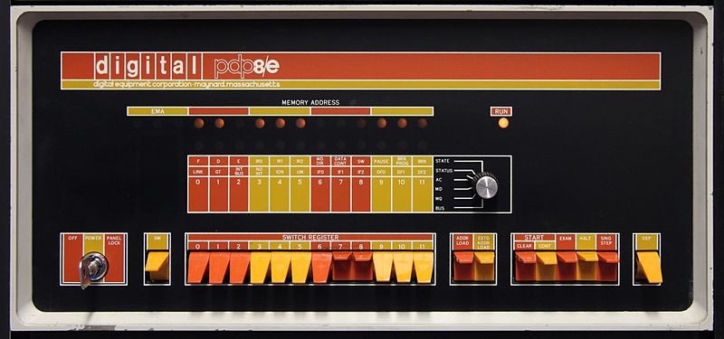
And even as microprocessors arrived, this archaic tradition persisted. But WHY BINARY ? The above front panel has a 6-position rotary encoder and, as this IBM System/34 panel shows, people knew that hexadecimal rotary encoders existed in the 70s:
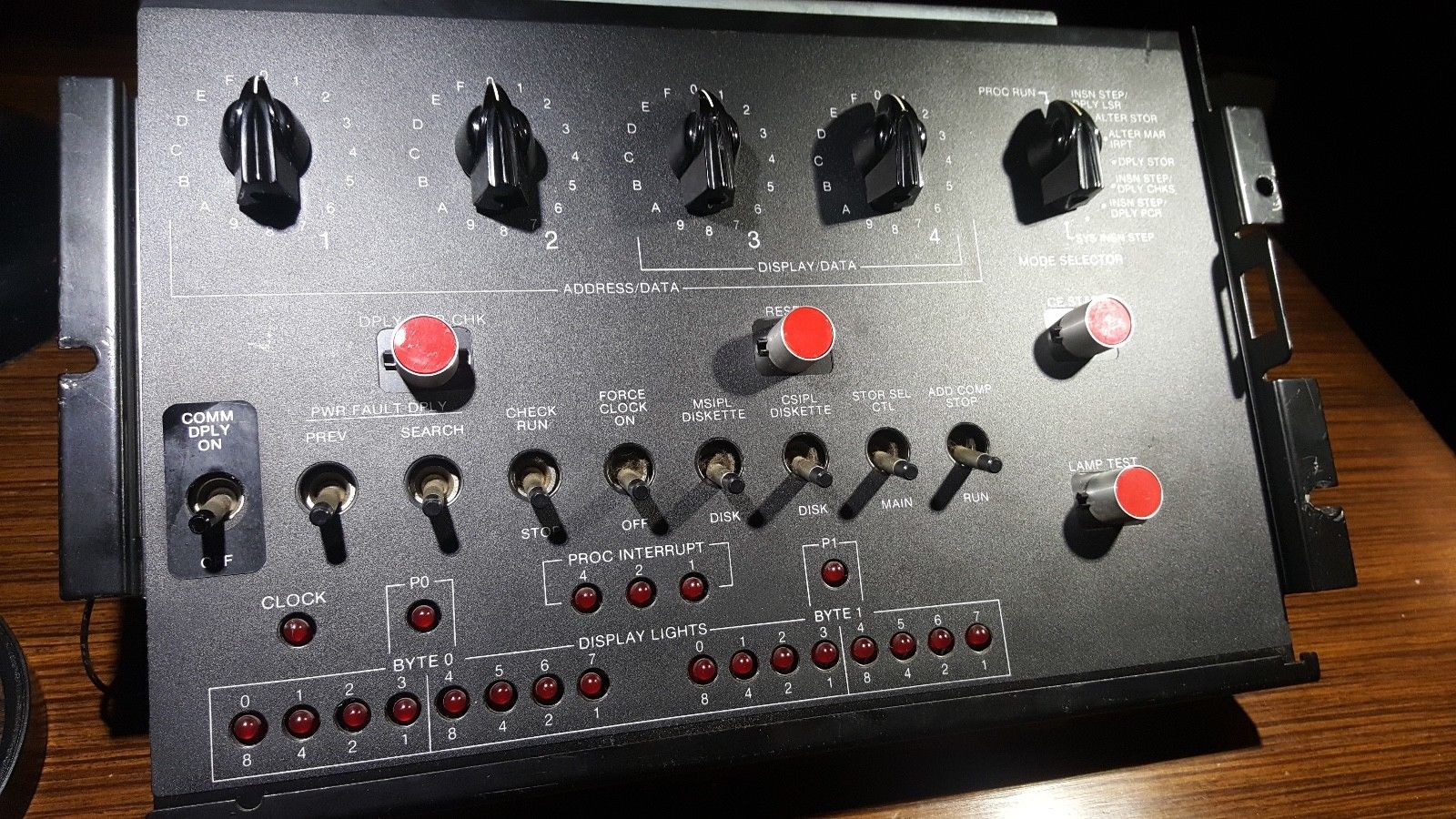
Isn't it way better than toggling countless buttons ? Hexadecimal encoders are awesome, no ? So I bought some on eBay when I found them, many years ago :-)
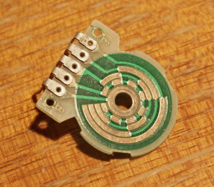
I have featured them on past projects such as my frequency generator:
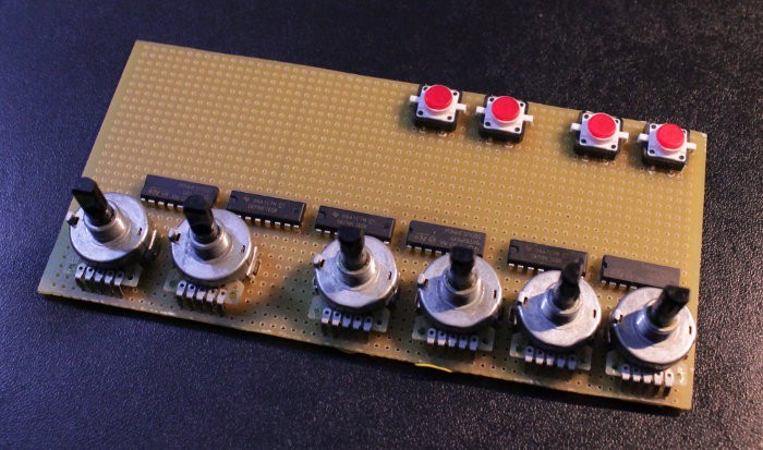
And for #YGREC16 - YG's 16bits Relay Electric Computer I used more of them :-D
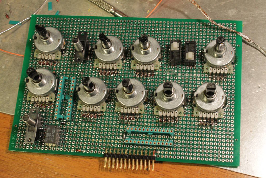
The front panel has two main purposes.
- enter programs
- diagnose, inspect, control the hardware
It appears that 1) is a special case of 2) and the front panel must be carefully designed to provide enough introspection features. Actually, it's even part of a larger 3) debug software. So the panel of this project is in fact the central module of the debug system of the processor.
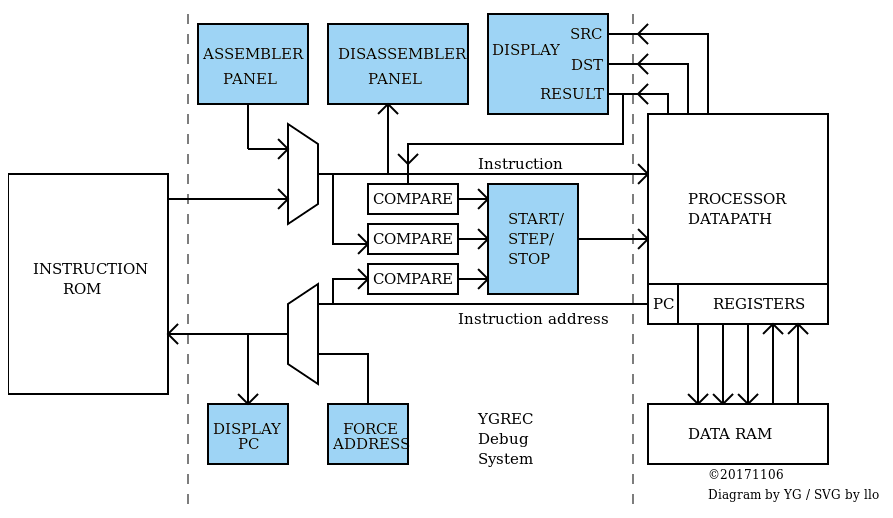
The above diagram shows the modules (in light blue) that this project aims to build.
- There are entry modules (switches and buttons) : the assembler panel, the start/step/stop logic, and the Force Address module.
- Most entry panels are coupled with a display panel : PC, Result, DST, SRC, Instruction (the disassembly panel).
Most values (except the instruction word) are 8-bits wide so 2 Hexadecimal modules are used for PC, Res, DST, SRC and the immediate field of the instruction. That's 2×5=10 modules to assemble. Which by chance is how many PCB I have ordered :-) (the 5 prototype boards would be used later for other purposes because their pinout and dimensions are not compatible so it would break the modularity of the whole design)
- The easiest part is what forces and displays the instruction address : it's a set of encoders and display modules, just 8 bits, with a multiplexer. And this byte force/display couple would be useful in other places later. The hack aspect would be with the multiplexing :-)
- Then the assembler and disassembler boards will follow the path already explored by the YGREC16, using the YGREC8's shorter and simpler instruction format.
Note : This is an electromechanical system, that also uses some diodes, but it will be easily interfaced with integrated circuits (via some electrical buffering). The switches would be operated by hand or via some software (a Pi, an Arduino or whatever) and the outputs could drive a YGREC8 implemented with transistors or integrated circuits.
It means that this EMUI will be useful later when the YGREC8 migrates to more modern technologies, and modularity is very important. It will speed up the implementation and debug of the planned transistors, CMOS and FPGA versions !
Logs:
1. Multiplexing
2. Tales of PDPs
3. Panel layout
4. Start/Step/Stop
5. The dawn of the micros
6. Numitron display modules
7. 25PDT
8. binary counter/divider with relays
9. Can I enhance the basic hysteretic latch circuit ?
10. Another relay-based divider... or is it ?
11. Don't go full Numitron ! Unless... OK whatever.
12. The assembler panel is working !
13. The importance of a good programming UI
14. Relay-based frequency divider
.
 Yann Guidon / YGDES