 Yann Guidon / YGDES
In this log we look at the electrical design of the instruction address bus, which drives the ROM address decoder and the display modules. The address is set by either the PC register, the EMUI switches or an external electronic controller.
The instruction bus has a similar design, except it has 16 bits and is driven by the diode ROM.
The obvious constraint is parts count since relays are not free and they dissipate a lot of power...
So in the beginning, we have the ROM decoder, driven in series with the display module. By design, the #Numitron Hexadecimal display module has a controlled and constant input impedance (one relay coil) that greatly simplifies the series connection. They are tied to the high side, so one only has to tie it to 0V to toggle the bit.
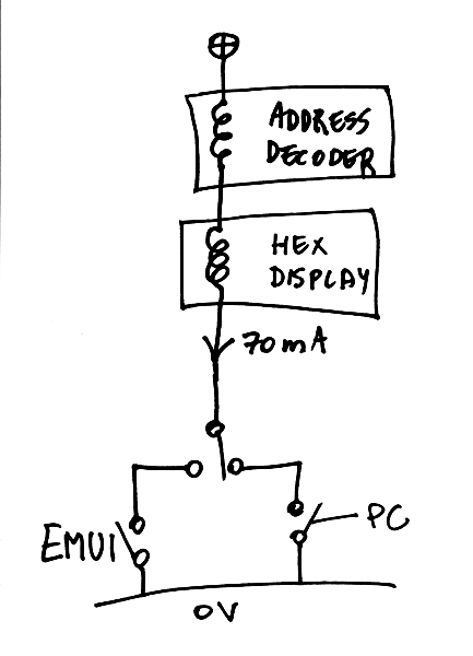
At 70mA, the relays are well driven, so the + side can be set at about 4V, or more if the decoder needs more coils in series.
The tricky part is the multiplexing : there is one SPDT switch that selects the source of data, and there are 8 bits to select. That would require an OPDT (Octuple Pole Dual Throw) switch, which, even though I have a few, is far from practical...
It is possible to remove the OPDT with the help of diodes and a single SPDT switch is required :
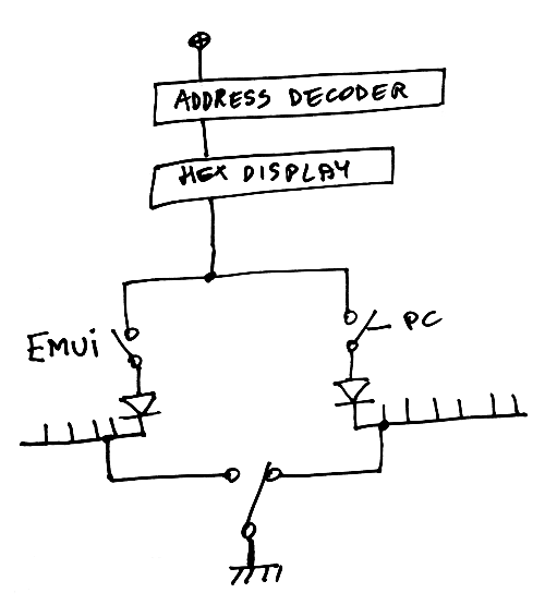
This adds about 0.7V to the supply voltage but it saves complexity elsewhere. And without the diodes, there would be shorts here and there...
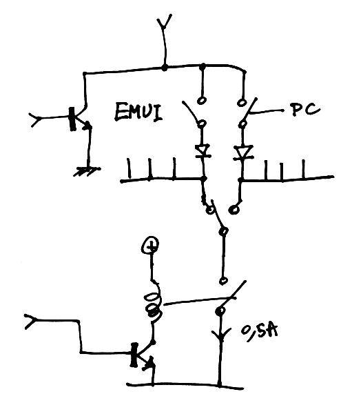
This switch is easily operated by the user. But it doesn't end here ! Now, we want the bus to be taken over by an external computer. A transistor can easily short the "bus" wire to ground but it also must prevent the other current path. This is solved with another relay. That relay must be "normally closed" and must stand at least 0.07×8=0.5A.
There is still the possibility that the user has left the SPDT switch in the position of the EMUI and that would prevent the external controller from letting the processor run freely... This is solved with the help of yet another relay that short-circuits the PC register rail to 0V, independently from the relay that inhibits the manual SPDT switch.
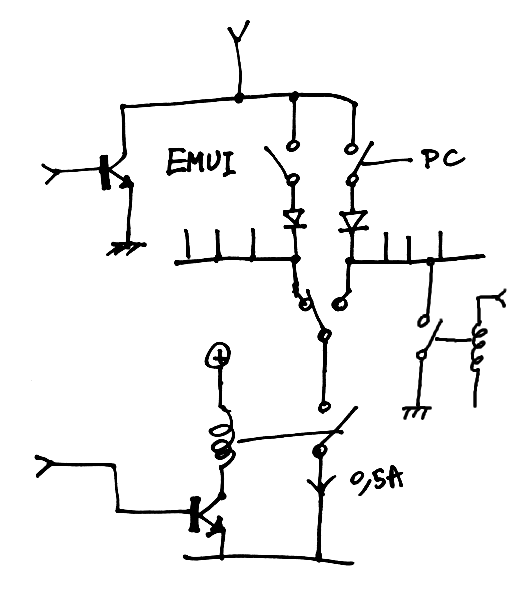
There are other possible configurations but there can be no fewer than 2 relays to get the desired functionality, and the system must be functional when the external control circuits are disabled...
Discussions
Become a Hackaday.io Member
Create an account to leave a comment. Already have an account? Log In.