 Daren Schwenke
Sub-project of: Arcus-3D-P1 Pick and place for 3D printers
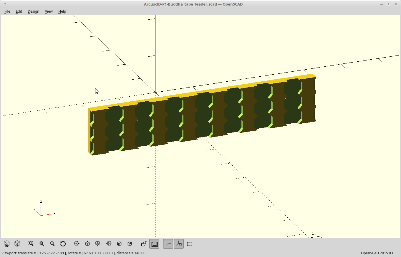
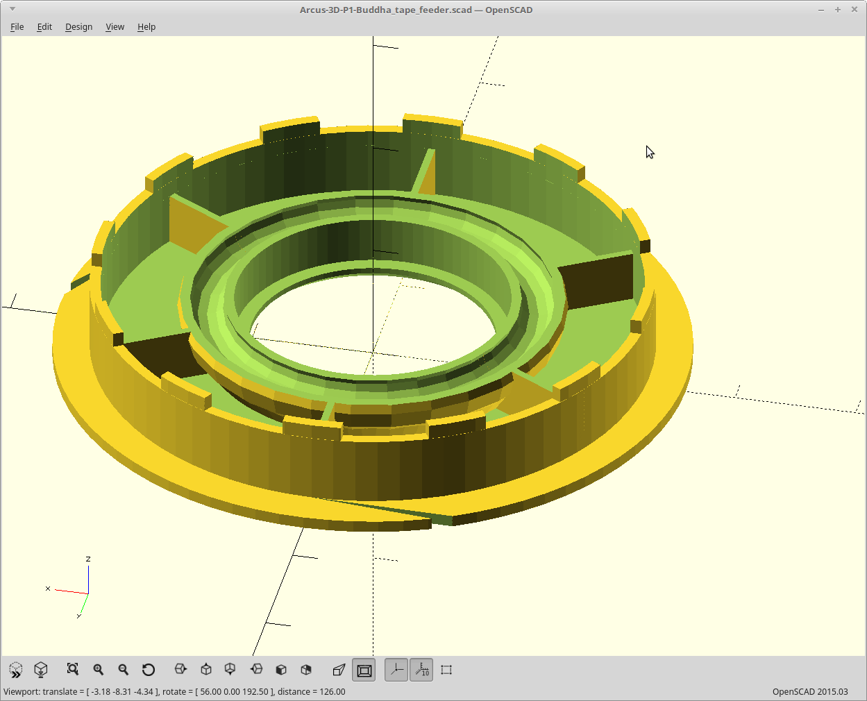
- Came in at <tape width> + 4mm. So for 8mm tape, it consumes 12mm of width which is just 1mm more than the reel the components come on. If you stack more than one, you can go thinner for the base plate.
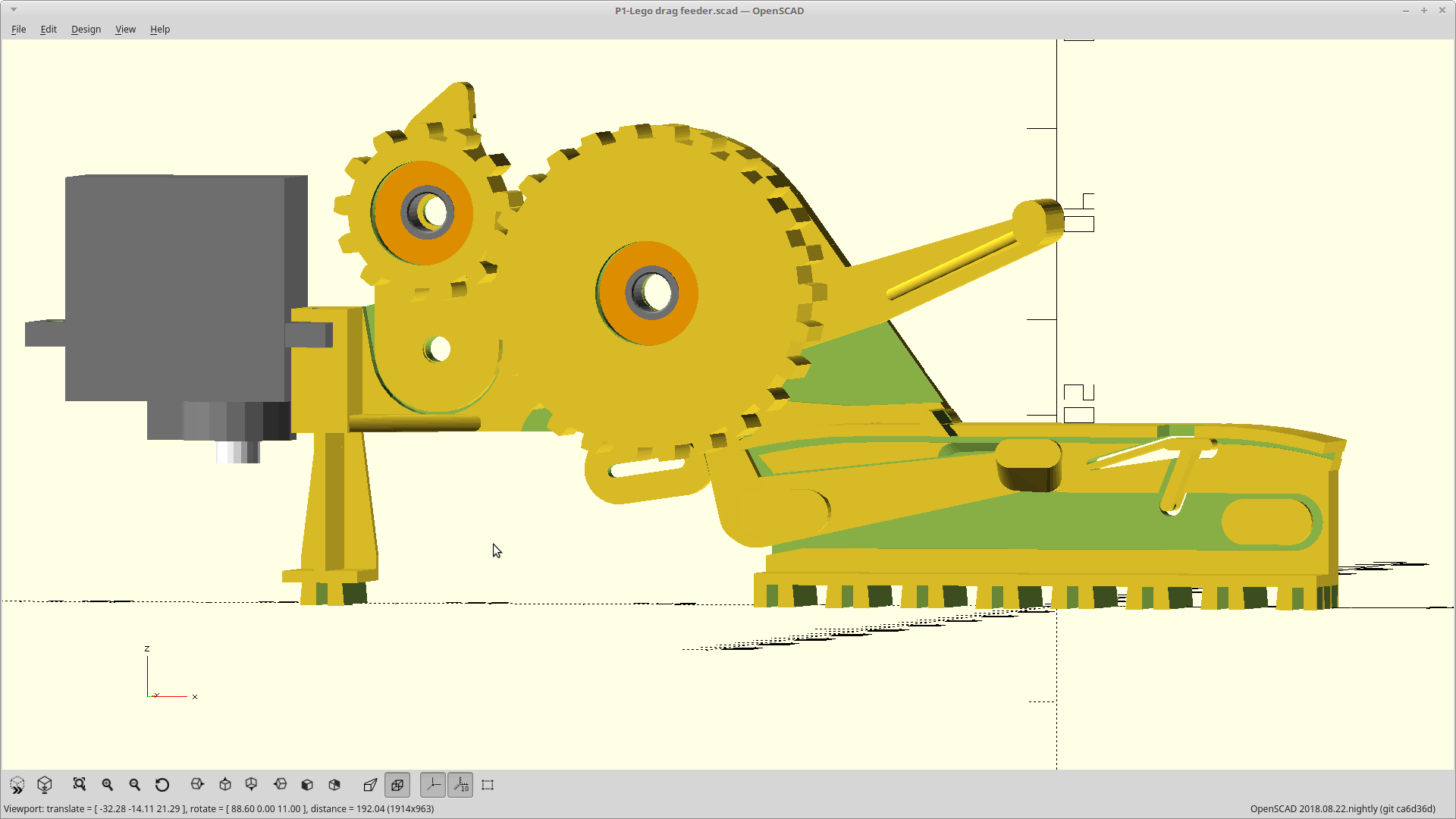
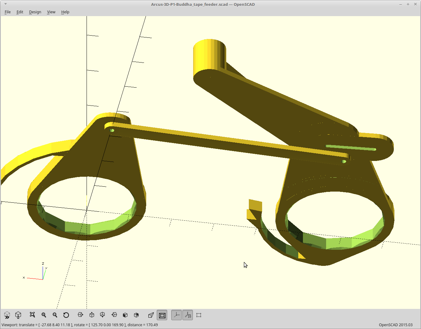
- Drives the tape with a sprocket on the release stroke of the feed lever to the same position.
- Supports the tape up against the cover window from both edges, and centers it.
- Removes the cover tape and has an integral slipper clutch so you can adjust the tension of the tape pull. Rotation of the cover tape removal can be switched from during tape advancement to opposing tape advancement by changing 2 parts.
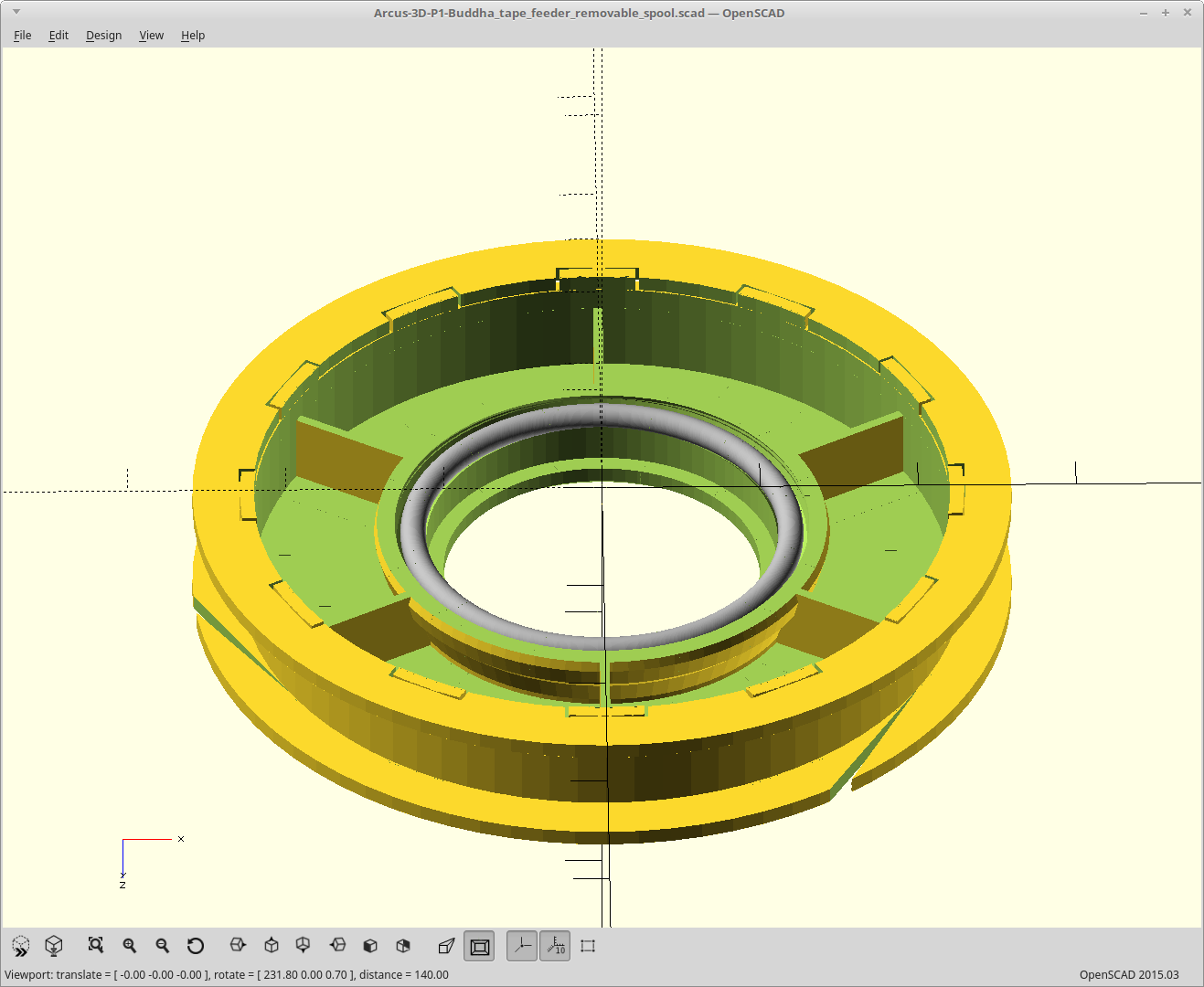
- Supports tapes up to 8mm depth relative to their top surface at the same depth, with no adjustments. Supports tapes up to 24mm wide by changing 2 parts, which are parameterized. Tapes with feed holes on both edges are supported.
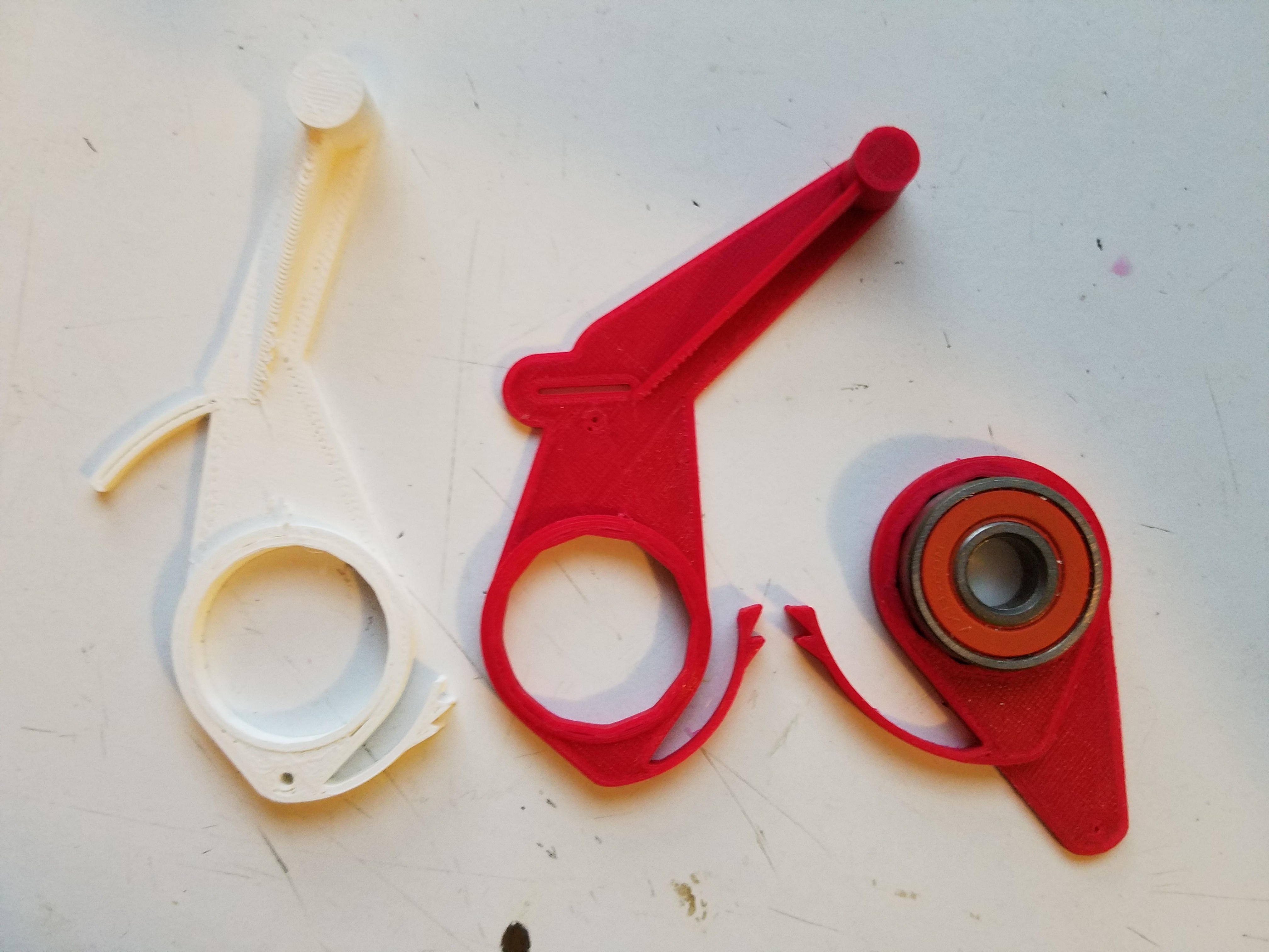
- All cams and ratchets are spring loaded and positive acting (force on them engages them more).
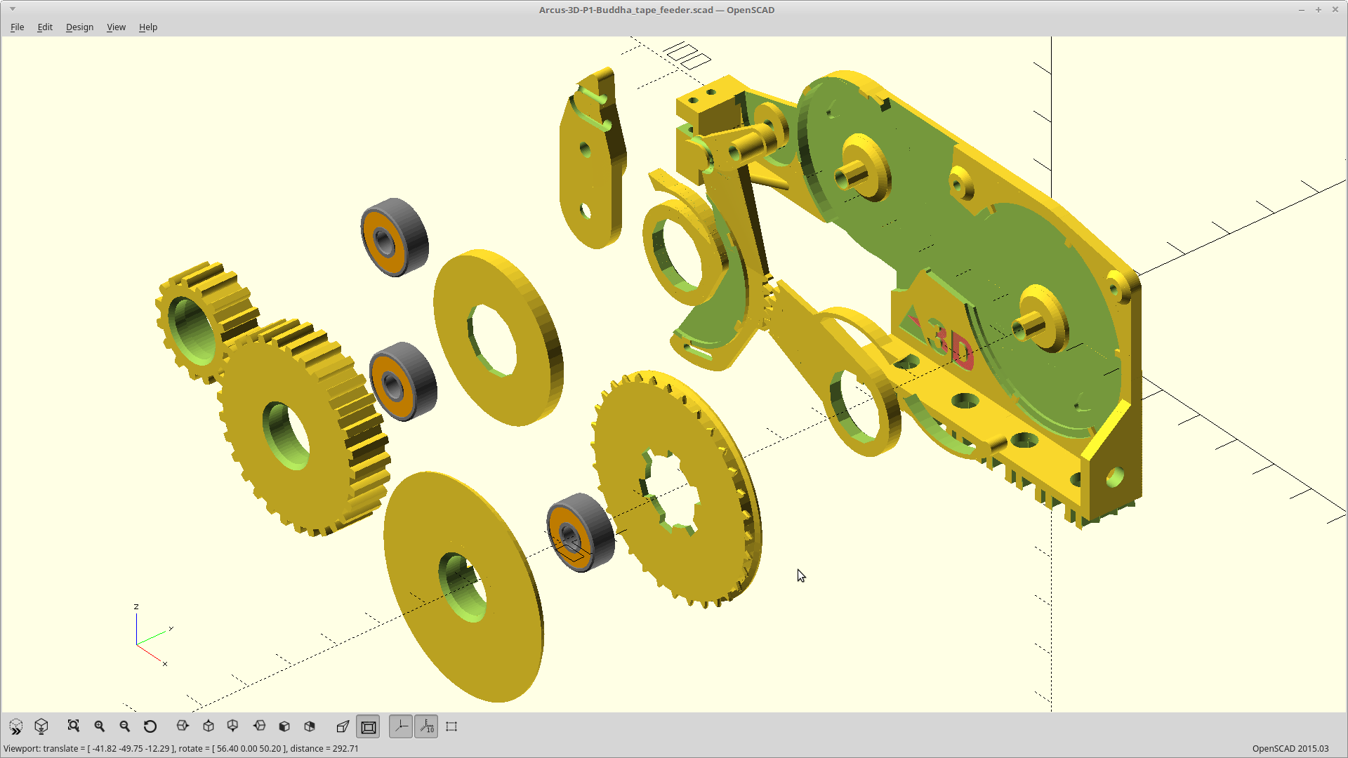
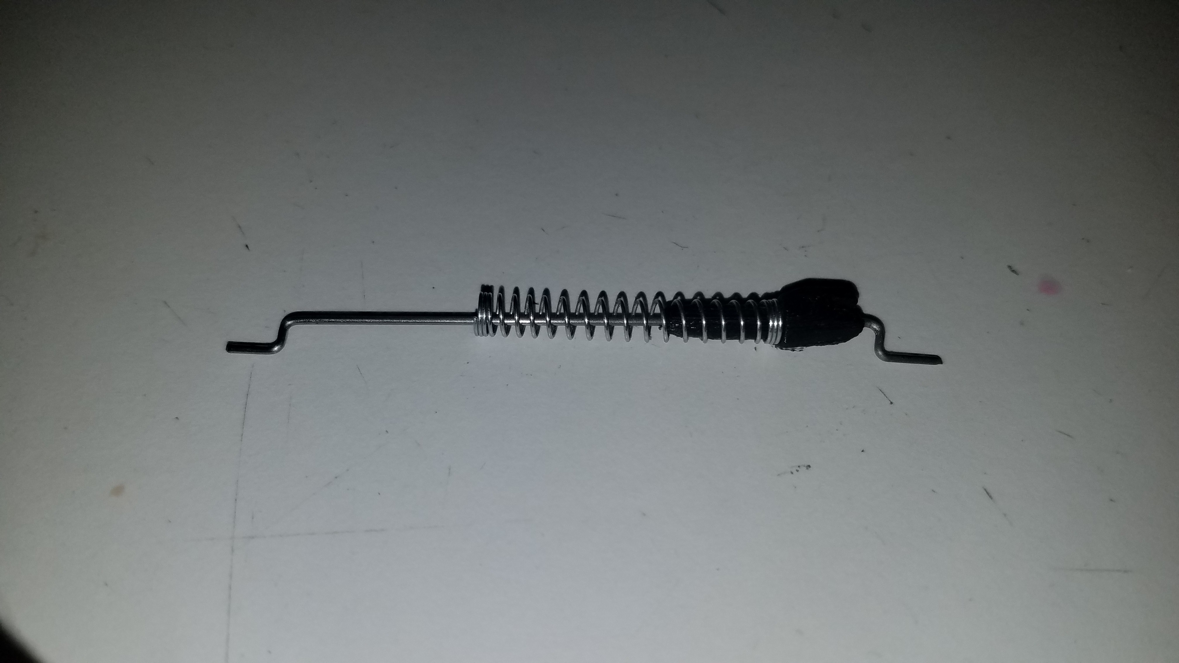
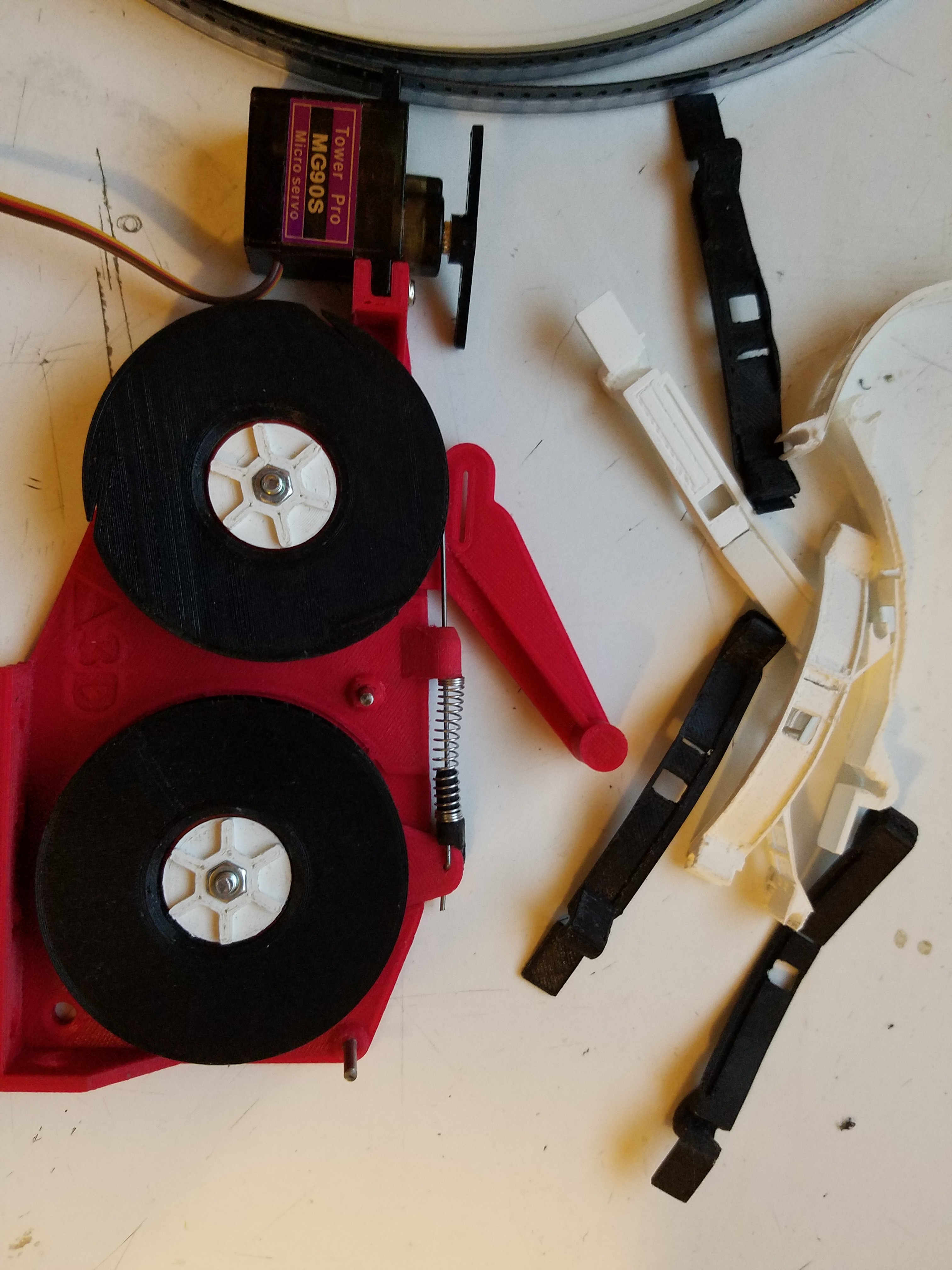
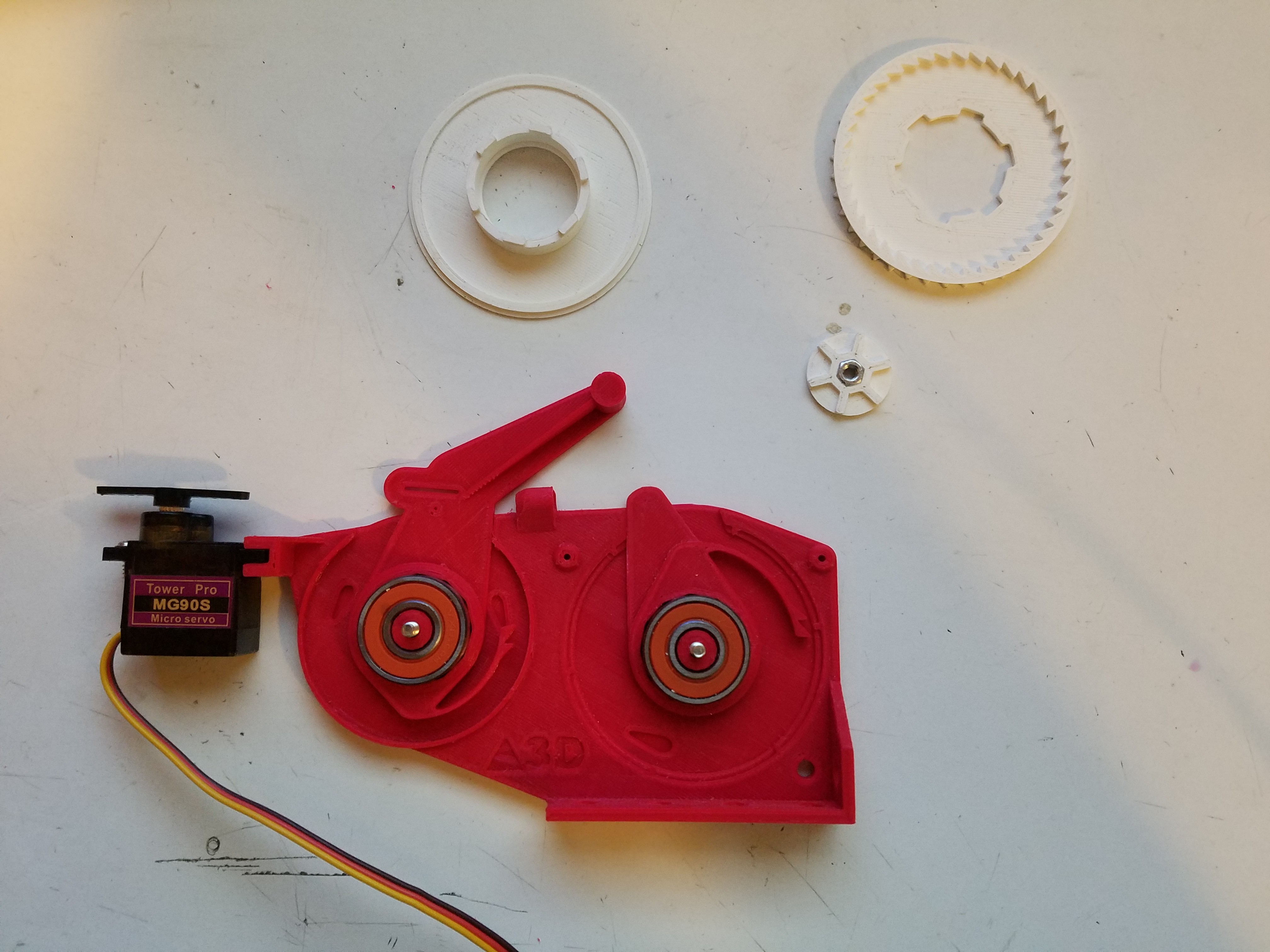
- For hardware, it requires two skateboard bearings, two M3 bolts, two M3 nuts, one (optional) O-ring, a 20mm length of 2.0mm piano wire, 100mm of 1.0mm piano wire, and a pen spring.
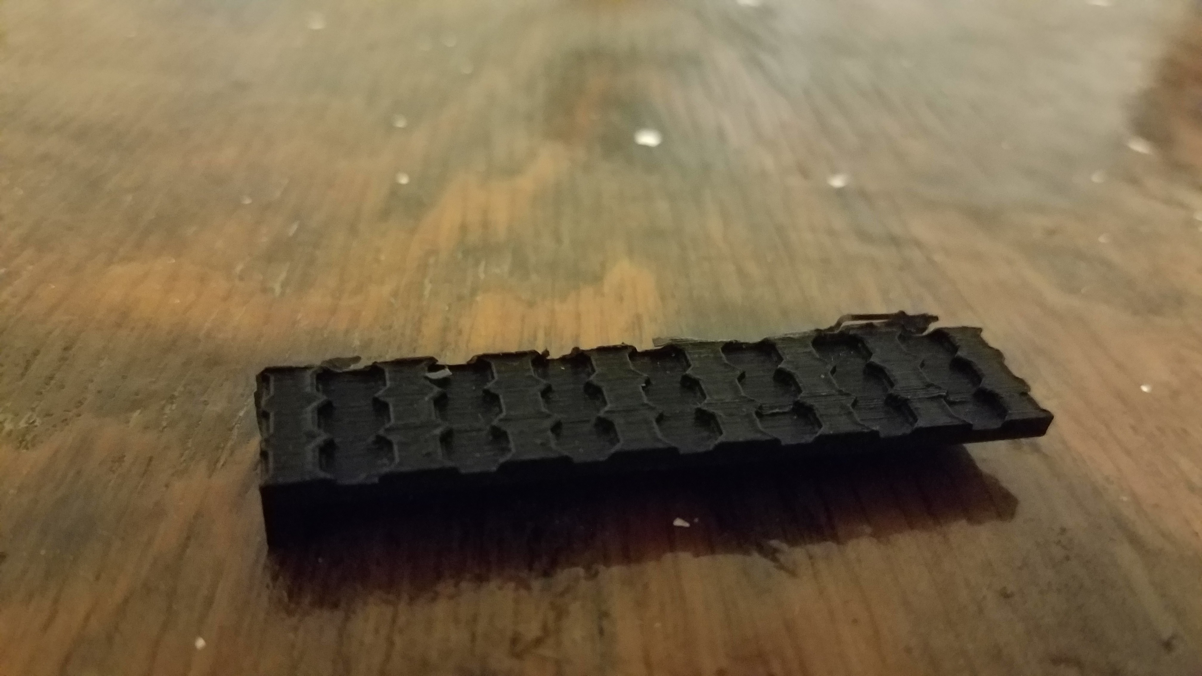
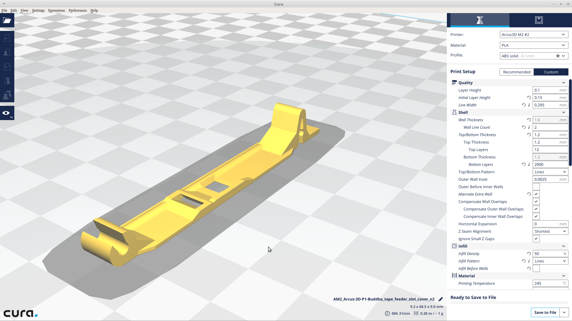
- Must be printed with a relatively fresh 0.3mm nozzle on a well tuned 3D printer. Accuracy of the ratchets and tape drive ratchet wheel are critical. The rest you can fudge a little on, but 0.3mm will work the best because the whole model is done as multiples of 0.3mm.


 Jose Ignacio Romero
 Nikolai Ovesen
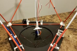
 Brandon Hart
Hello!
Is there a version for repeating? I want to try this feeder.