 Maximiliano Rojas
This system must acquire the position an orientation of its end effector or, to be practical, of the module connected in the end effector, for this purpose, a typical six degrees of freedom robot structure has chosen (like touch haptic system) whose end effector will have an extension to add and remove modules easily, these modules can be whose presented here or any other of your creation. The intention is to create something versatile and flexible and portable, so a circuit that can provide a constant power and regulate it will be present in a next stage.
1 Mechanic design and mathematic modeling
In a standard six degrees of freedom robotic arm structure, every degree is a revolute one, so potentiometers should work for angle sensing, as I guess in Touch haptic system, two three potentiometers must remain in the base and a pulley must be used to measure the wrist angle, the structure is:
 general structure. B) Structure that will be used.")
A) general structure. B) Structure that will be used.
The main measures of the structure, in millimeters (because of metric systems rules, yes, I'm a fanboy of metric system), are:
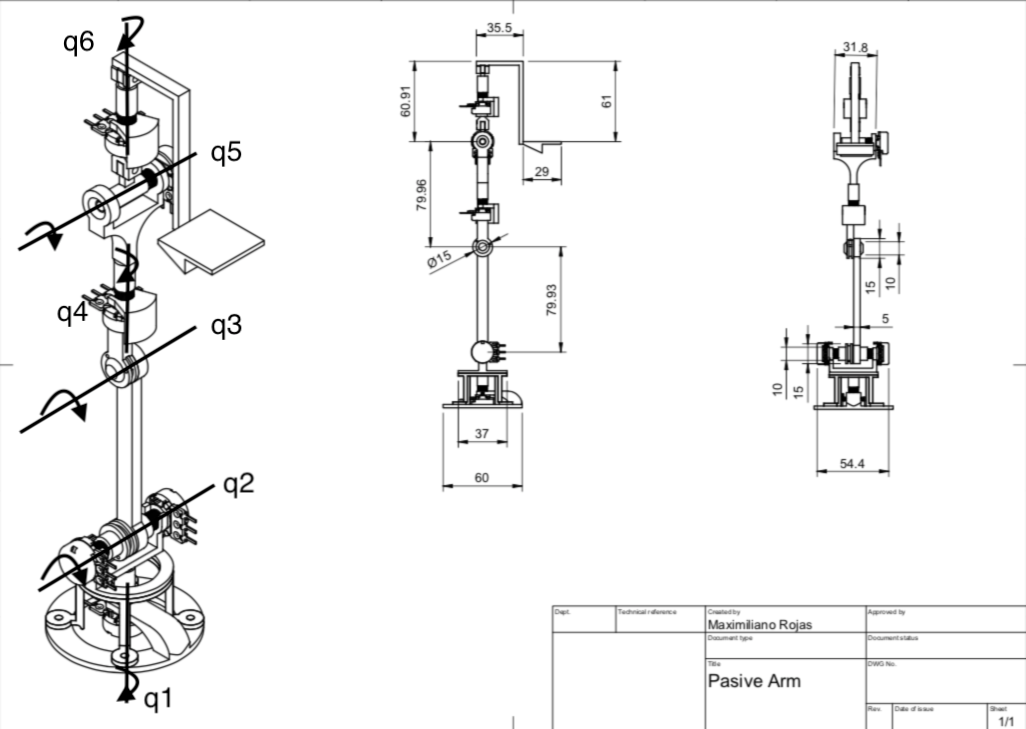
There are a q(n) axes in the last image, this represents the axis where the angles will be measured,as you can see, there are two potentiometers in q2 axis, this is for maintaining the major quantity of sensors in the base. To measure the q3 angle we can measure the angular difference between the potentiometer connected through a pulley to q3 and the potentiometer who measure the q2 angle.
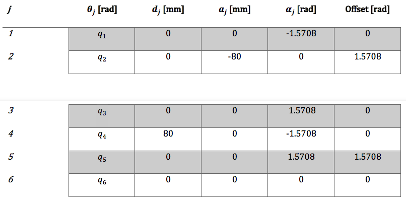
To calculate D-H parameters we must put a frame of reference in each revolute degree of freedom q(n), in this way we can do the corresponding relations be to obtain the homogenous matrix of each frame and then, obtain the forward kinematics equations, for this I used MatLab with its robotics toolbox, then the parameters are:
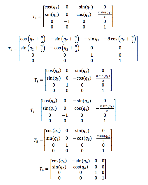
Now we just replace this values in the standard homogenous matrix presented in State of the art stage, where T(n) represents the matrix of q(n) frame:
To obtain the position and orientation of the end effector with respect to the base we must multiply all this matrix, then, the equations obtained can be freely implemented in an embedded system, microcontroller, pc, or any other programmable system that support this processing. Tf represents the final matrix:
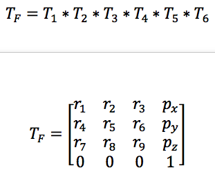
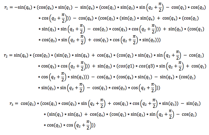

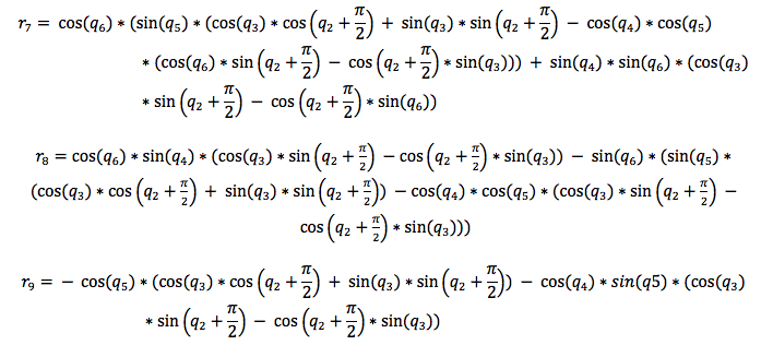
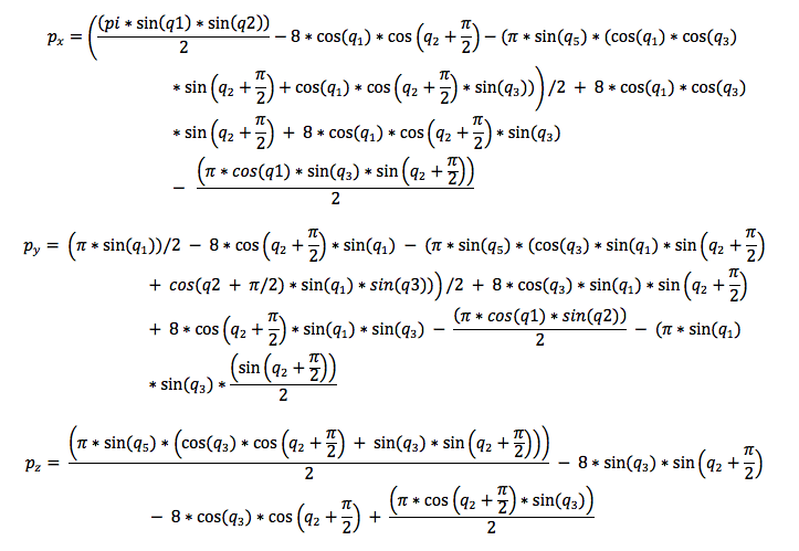
* Don't worry, I'll upload a word file with these equations.
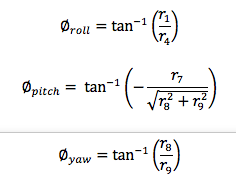
The position vector can be extracted directly from the Tf matrix, but to obtain the orientation in terms of Roll, Pitch, and Yaw angles we must establish some relations between the components of the rotation matrix, then:
2 Coding
The scheme of the algorithm will serve as a base for any application that you build, for this reason, the necessary parts of the algorithm being deepened and explained, so :
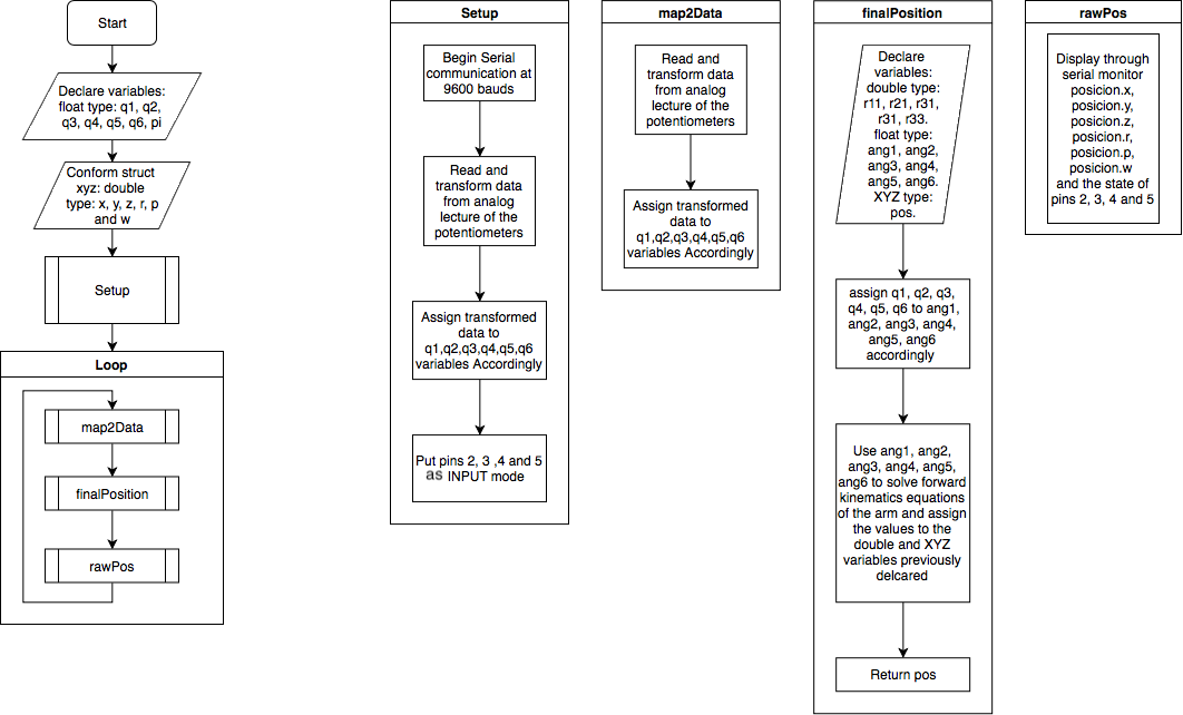
You can appreciate that the flow of the coding is simple, first, you declare the variables that serve to save the respective angles of q(n) and to display the information of interest (like [x y z ] position and [r p y] angles), later, through the "setup" sub-process the initial configurations are established.
Inside the sub-routines, in the iteration part, it can be appreciated a very logic structure, first, a lecture of the voltage of the potentiometers is done for, then, transform it to a useful range in radians (this process is done by "map2Data" sub-routine), next, an auxiliary variables are declared to calculate de forward kinematics equations, in this way it can return the components of the Tf matrix (this process is done by "finalPosition" sub-routine), last, the values obtained are displayed through serial monitor (this process is done by "rawPos" sub-routine).
If the code is structured in functions, is proper to guess that the implementation in other projects will be easy and fast, after all this is one of the main goals.
3 Test
movements, looks erratics, so at the end of this project, I will add a first IIR filter that corrects that.
Discussions
Become a Hackaday.io Member
Create an account to leave a comment. Already have an account? Log In.