Functional Description
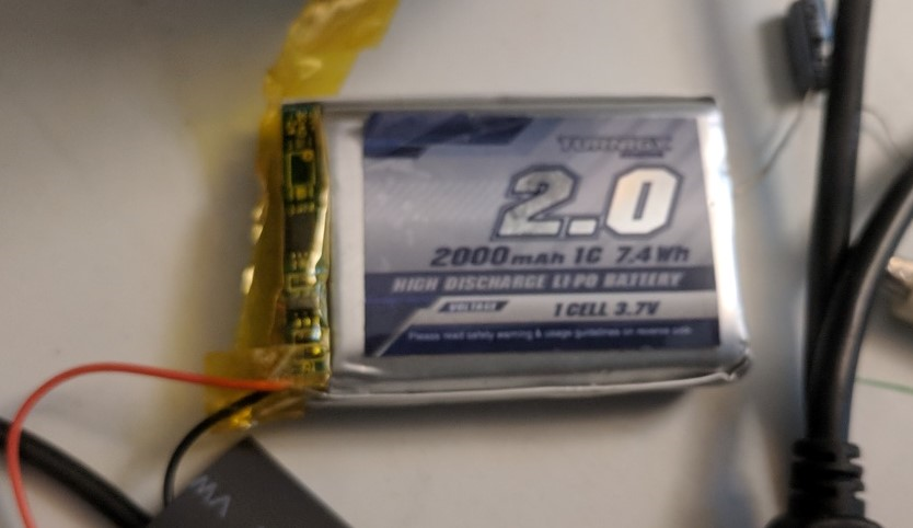
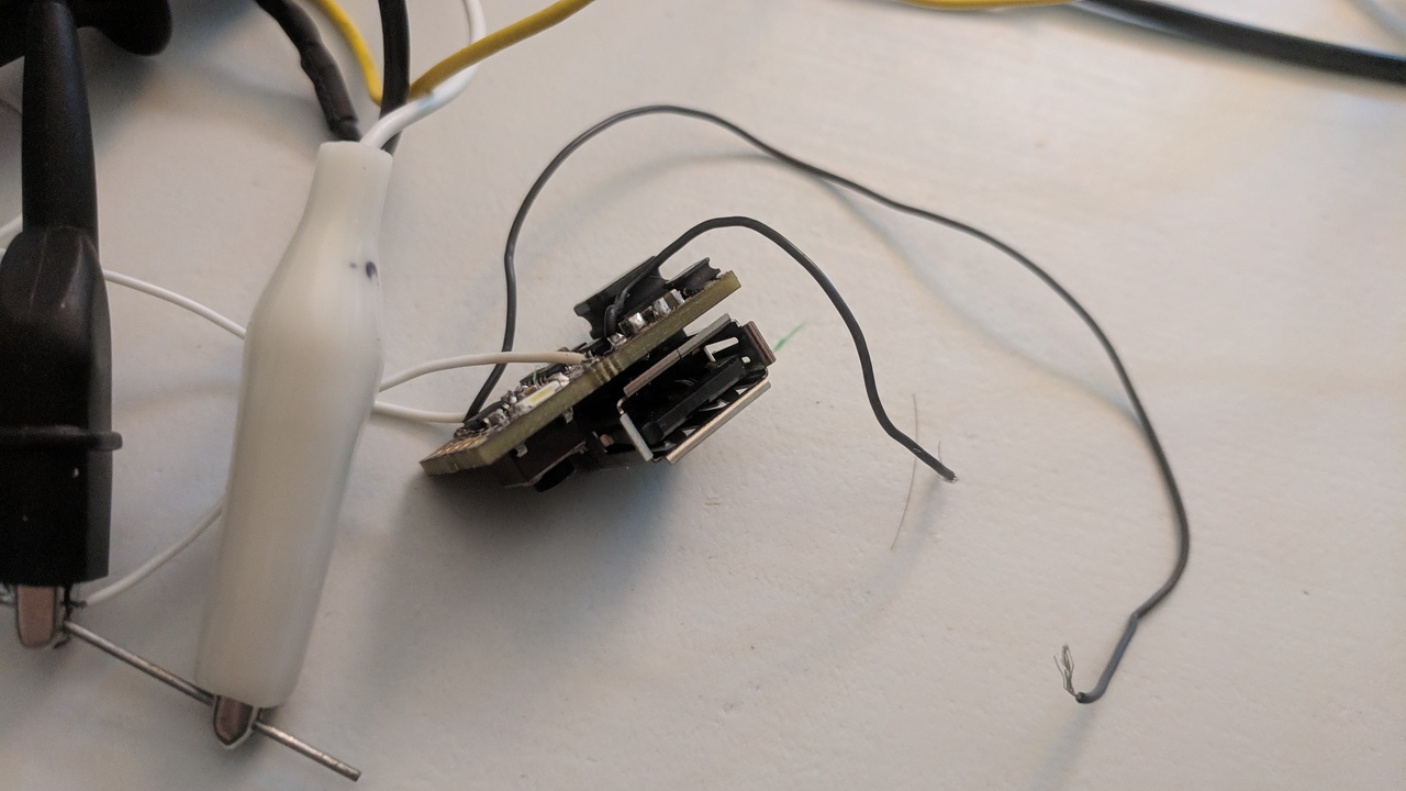
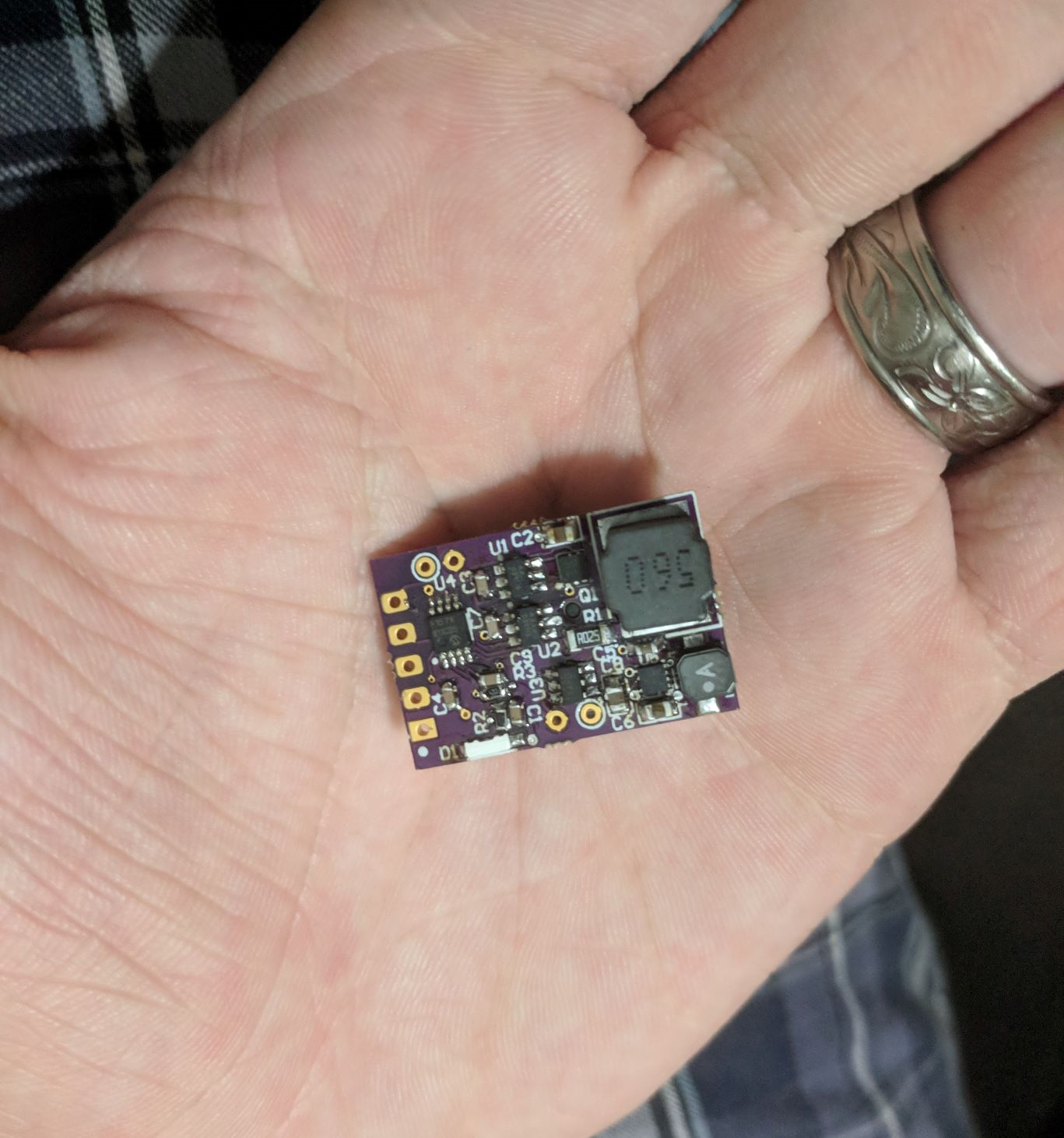
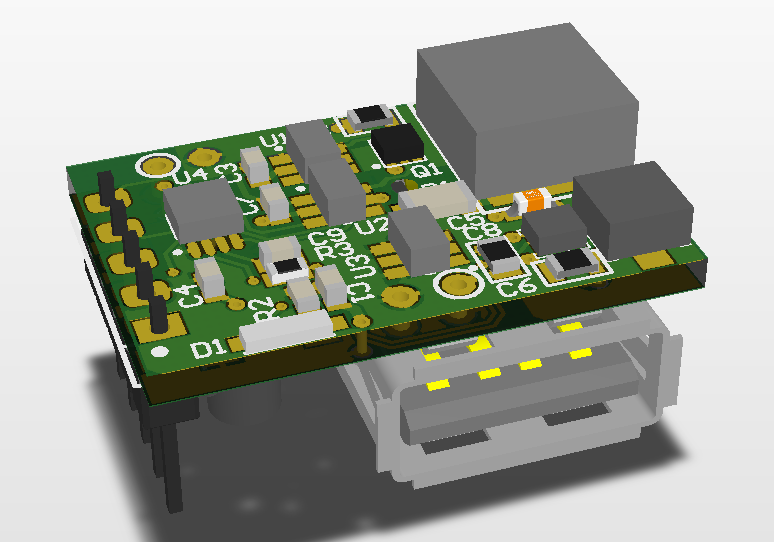
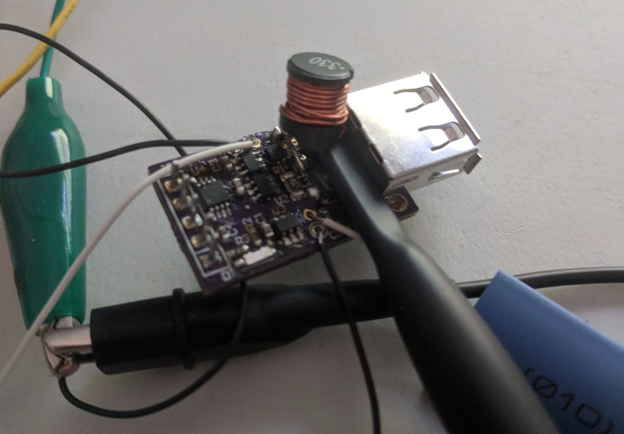
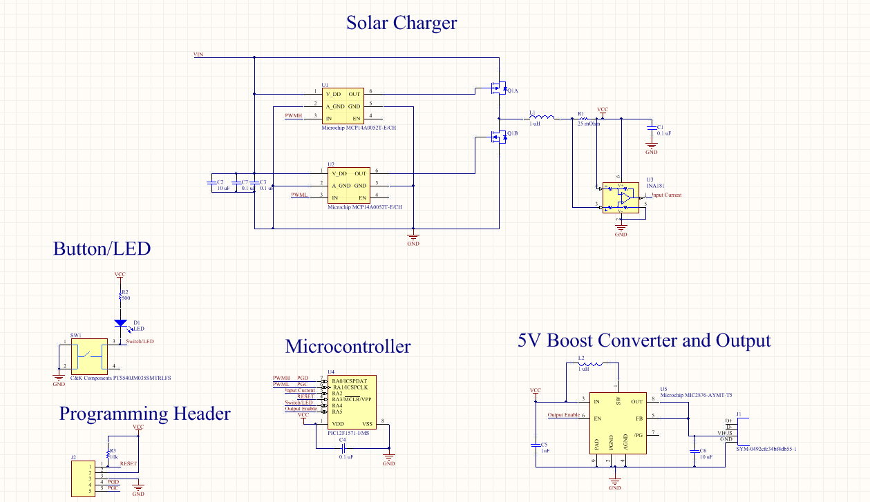
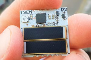
The circuit in this project contains two power circuits. The first is a synchronous buck converter, controlled by a microcontroller carrying out MPPT, to send power from a 2 watt, 6 volt solar panel into a small lithium battery cell. The second is a boost converter that provides 5 volts for USB charging from the lithium cell.
Normally, this small of solar panel would be inefficient and unreliable when charging USB, as the power available and the power requested would never match. The battery buffer fixes this: excess solar charges the battery, excess demand drains the battery. In the case where the demand continuously exceeds supply, the output can be shut off temporarily while the battery charges back up again.
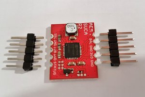
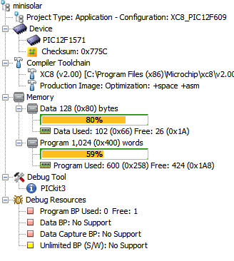
A bare-bones microcontroller, the PIC12, provides control for this project. It measures current and battery voltage, then controls the MPPT and can turn the output on or off. There is also a bright white LED that serves double duty as an indicator and a flashlight. Lastly, a small button engages the indicator/flashlight. All of these functions are done with very strategic allocation of the extremely limited resources of the microcontroller.
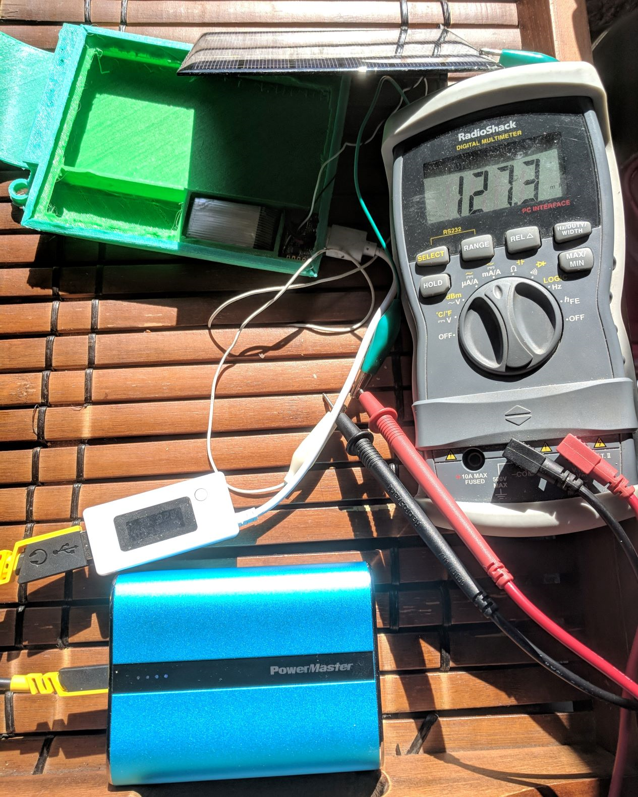
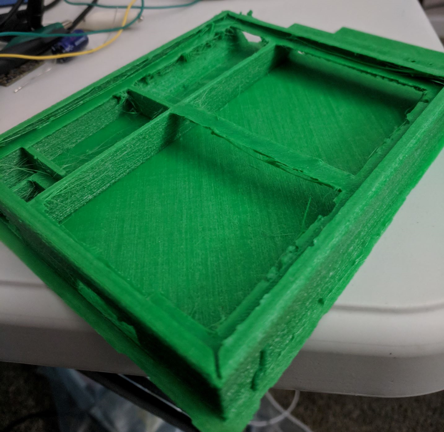
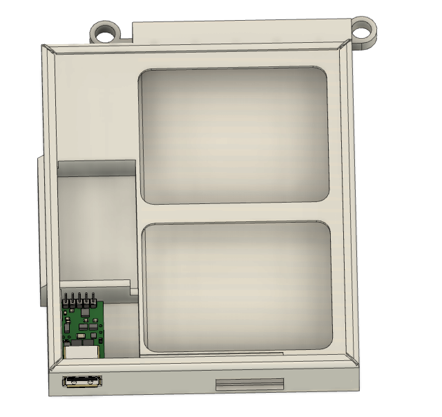
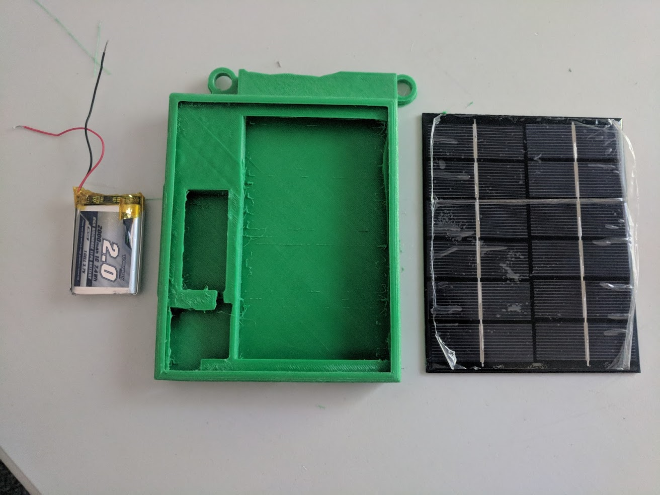
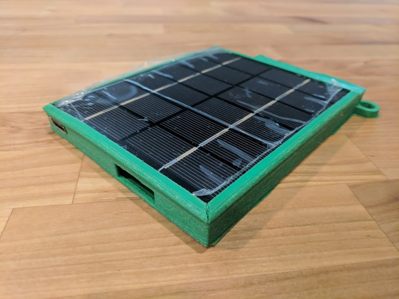
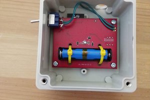
The circuit and battery are placed in a 3-D printed enclosure, which also includes a phone sleeve and a housing for the solar panel. The result is a portable little box that should be able to keep a phone charged indefinitely during outdoor activity.
Objectives and Specs
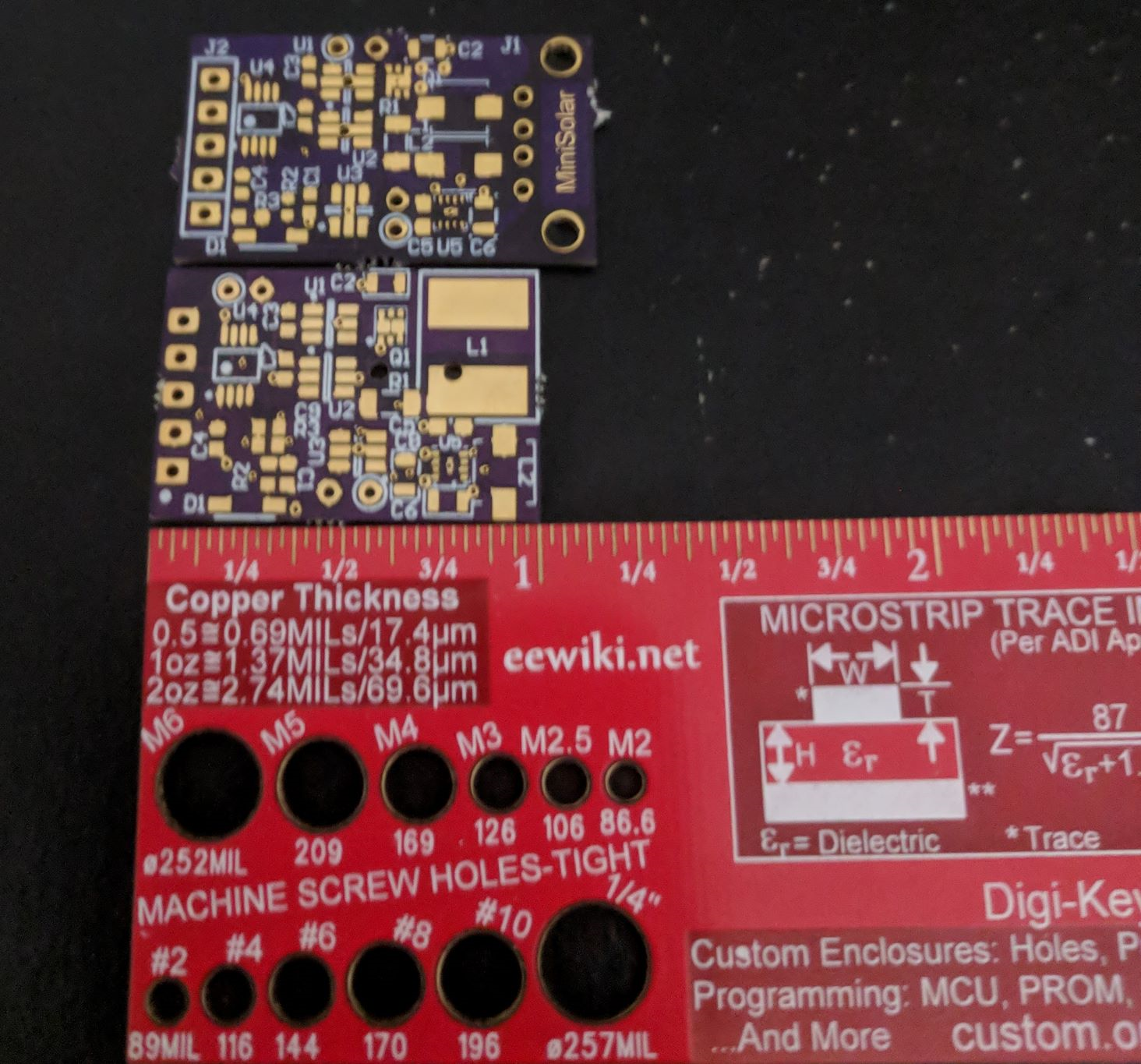
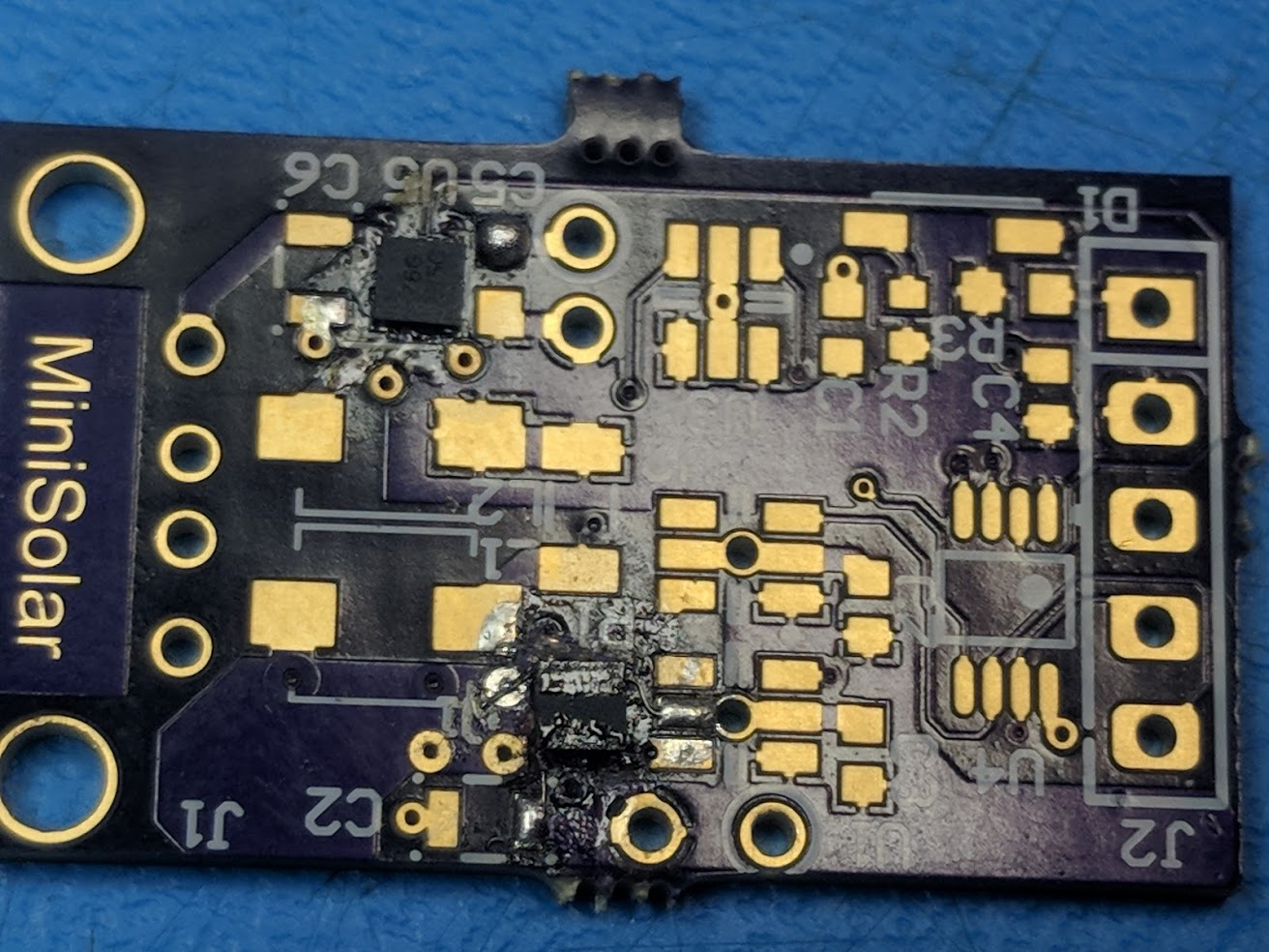
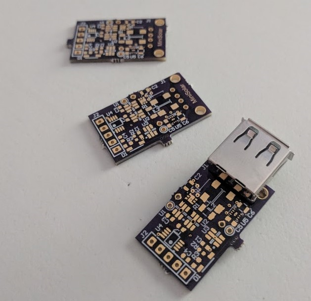
The objectives for this project are low cost, small size, and high efficiency. The PCB components total about $9 in single quantity. The total material cost, including components, PCB, battery, and solar panel, is about $20.
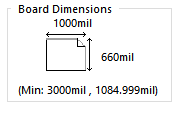
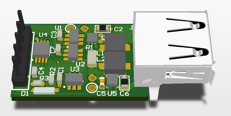
The dimensions of the PCB are 1.00 x 0.66 inches.
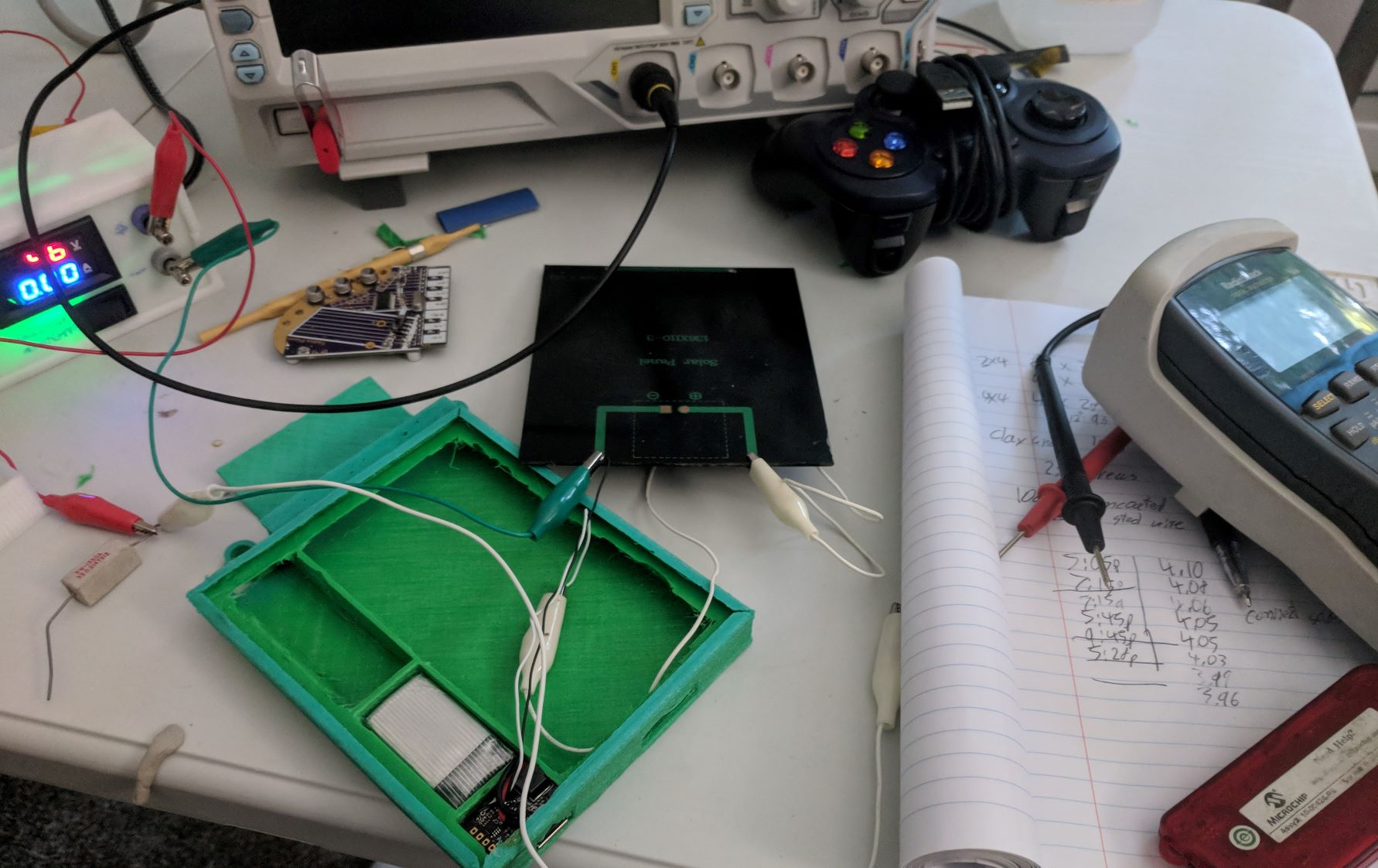
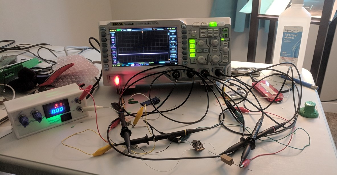
The efficiency of the solar to battery buck converter was measured to be roughly 90%. The efficiency of the battery to USB boost converter is listed in the datasheet to be up to 95%.
The input power is limited by the size of the inductor; its current rating is 1.75 A. With a (worst case) battery voltage of 3.0 V, this restricts the solar panel to 5 W or less. A 6V (12 cell) panel is needed to consistently exceed the battery cell voltage. The solar panel's open-circuit voltage must not exceed 20 V to avoid damaging the circuit, but a 12 V (24 cell) panel should work.
The battery cell needs to be Li-Ion chemistry and capable of discharging at 2 A and charging at the solar panel maximum power. Otherwise, capacity is irrelevant. A small quadcopter battery works well to reduce weight.
The USB output circuit can technically deliver 3.8 A, but with no power negotiation circuit on the USB port, every device I've seen will draw no more than 1 A.
Renderings


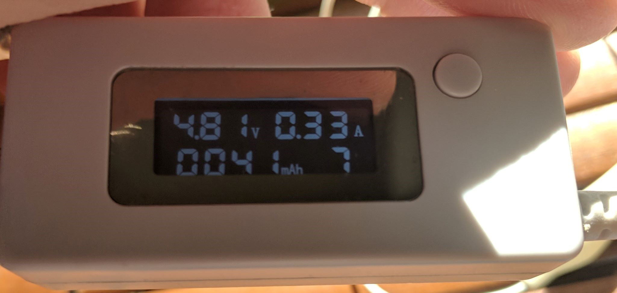
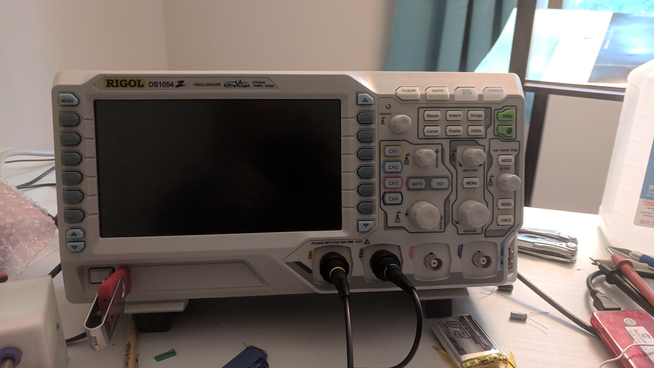
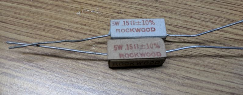
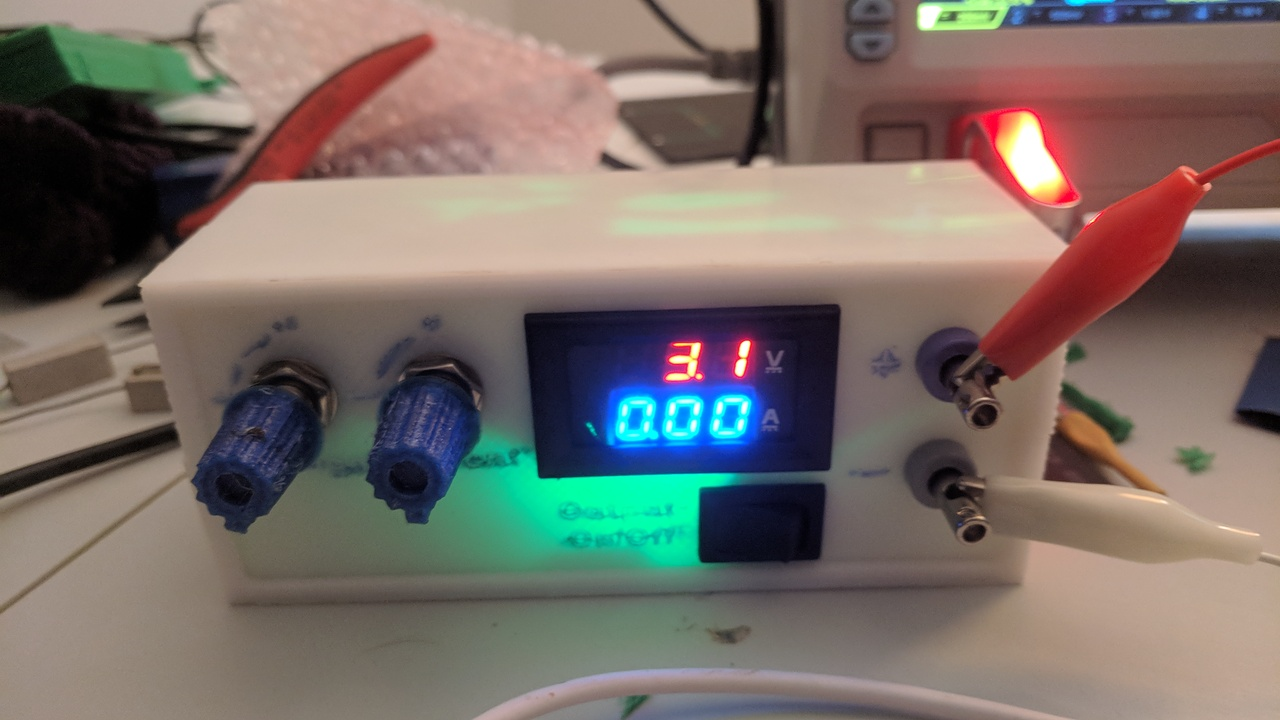
Demonstration

 Jasper Sikken
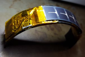
 DrYerzinia