 Jan
JanFeatures at a glance
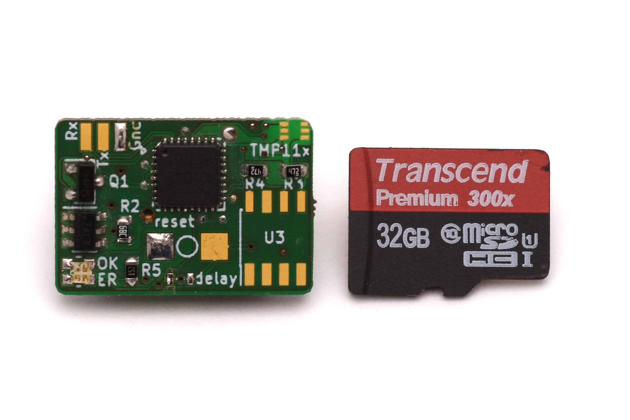
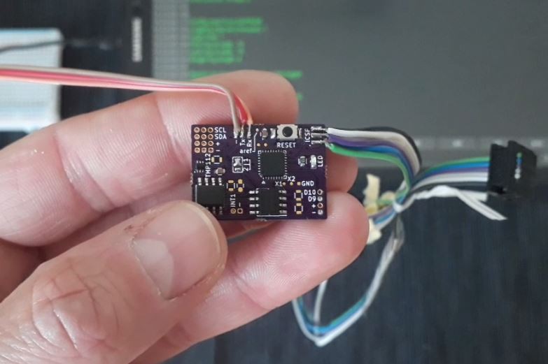
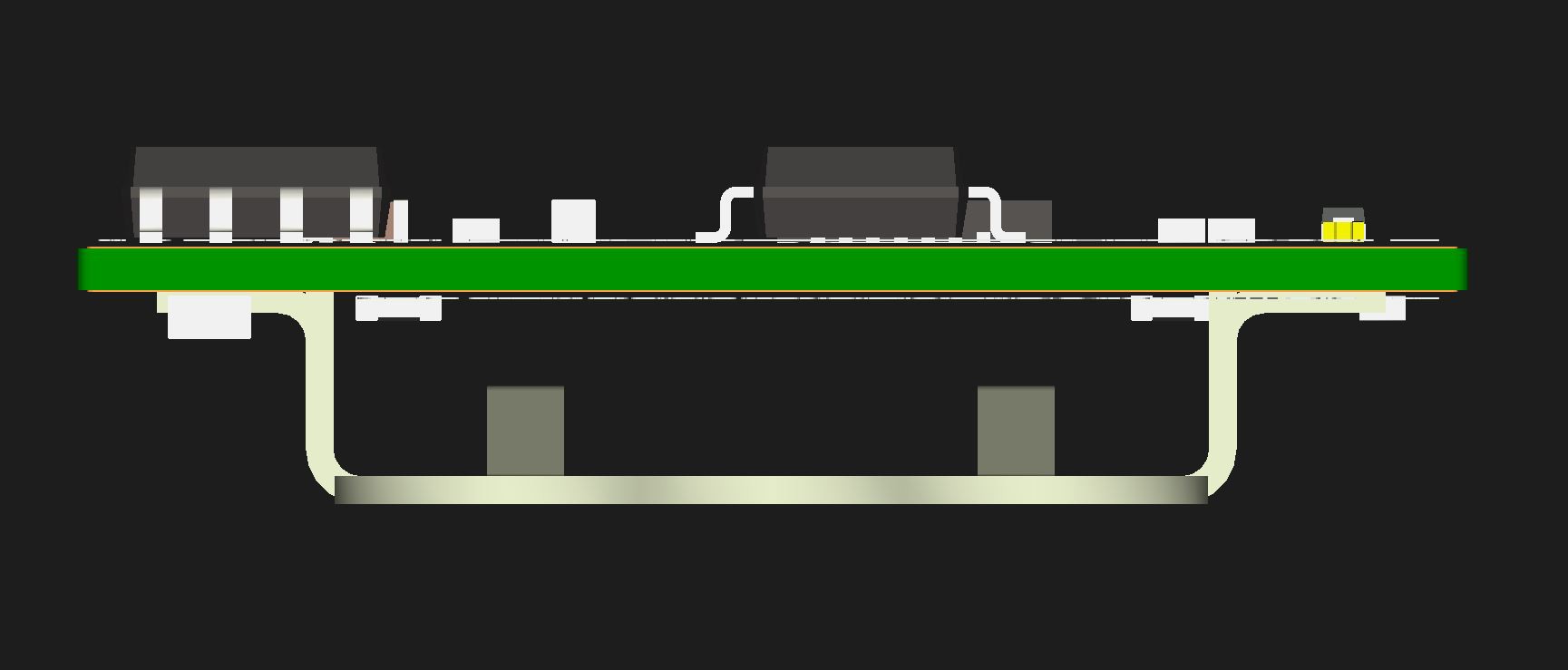
- small: only 25.3x18x8mm incl. battery holder
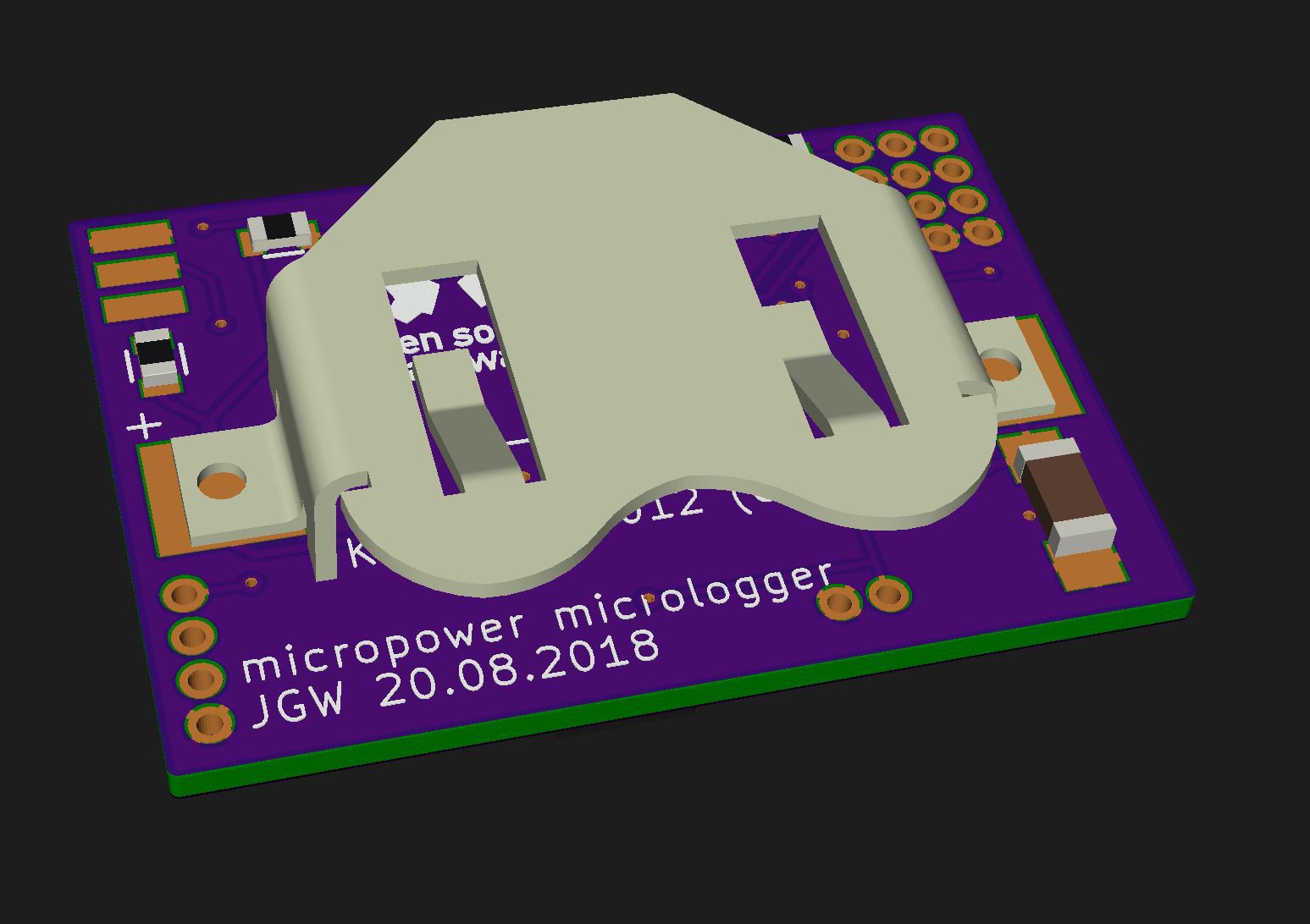
- low power: runtime 2 years (with a CR1632 120mAh coin cell, 4 logs/hr)
- versatile: use I2C or digital sensors (board runs from 3.3 to 1.8V)
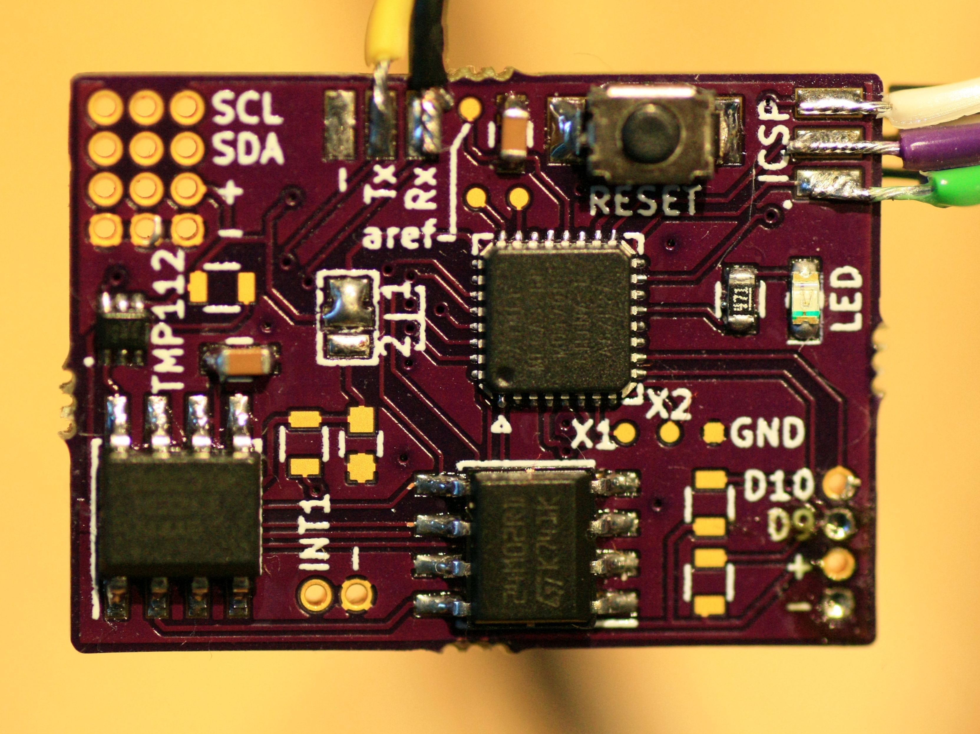
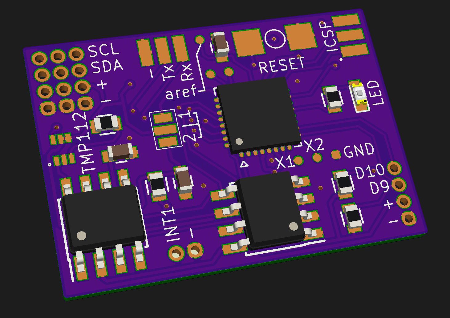
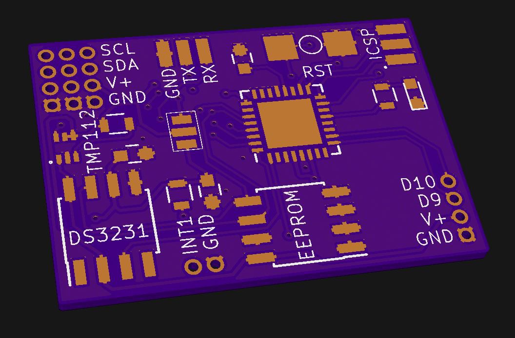
- 1x temperature sensor on-board, accuracy ± 0.5°C (TMP112, NIST-traceable)
- data retention > 200 years (depends on EEPROM manufacturer)
- data transfer via standard 9600 baud serial protocol (or faster, you decide!)
Functional specification
The following table shows the most important features I expect from my logger. There are of course more (e.g. LED for signaling, reset button, ...) but those will make it into the final design anyway!
| PARAMETER | VALUE/DATA | IMPORTANCE | STATUS |
| size | ≤25.4x25.4mm (1 square inch) (preferably 25x20mm) height < 10mm | REQUIRED DESIRED DESIRED | ✔ ✔ ✔ |
| operational life | > 1 year on a CR1225 button cell (48mAh) > 2 years on a CR1632 button cell (120mAh) | REQUIRED DESIRED | ✔ ✔ |
| RTC | temp. compensated RTC (DS3231MZ+) | REQUIRED | ✔ |
| accuracy | T ± 0.5°C | REQUIRED | ✔ |
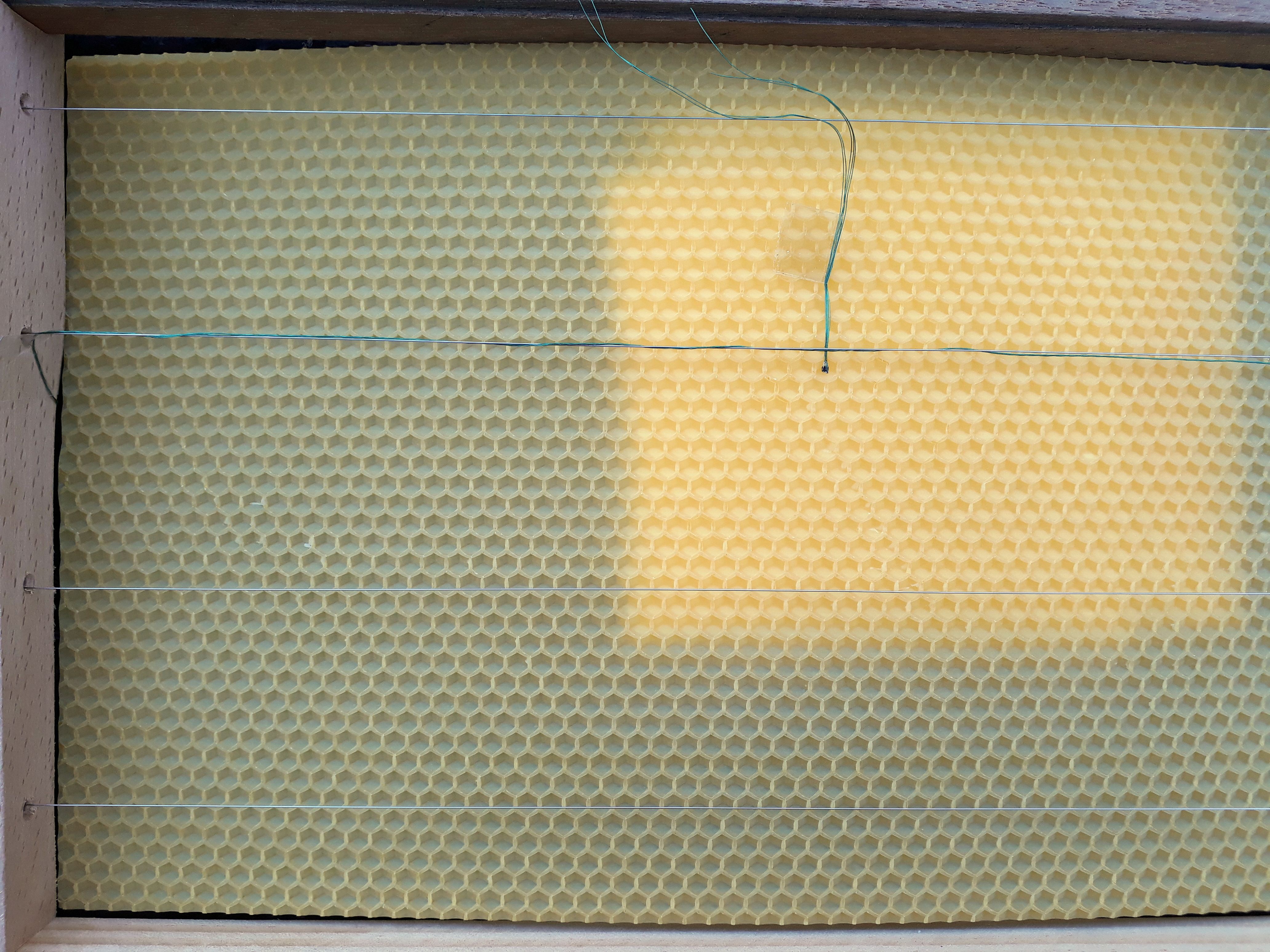
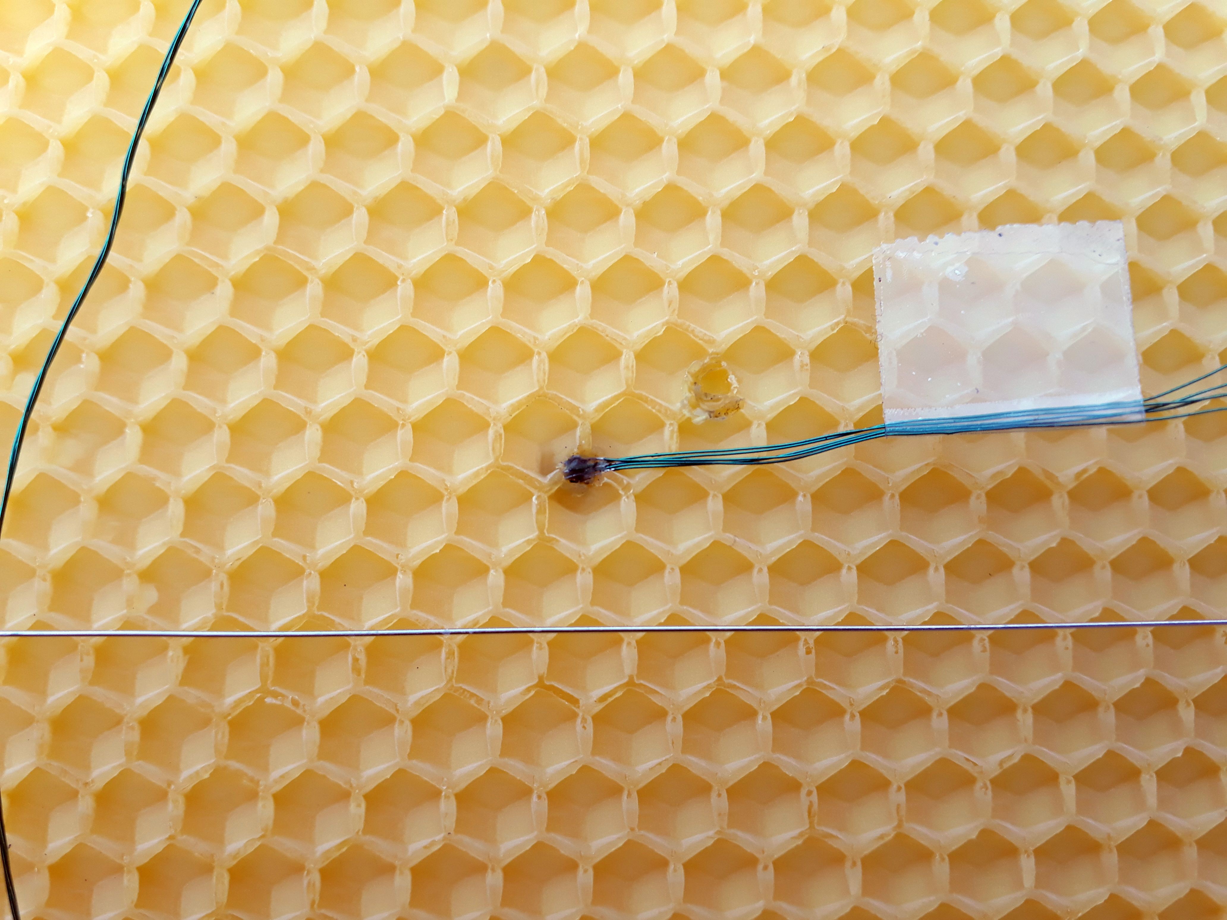
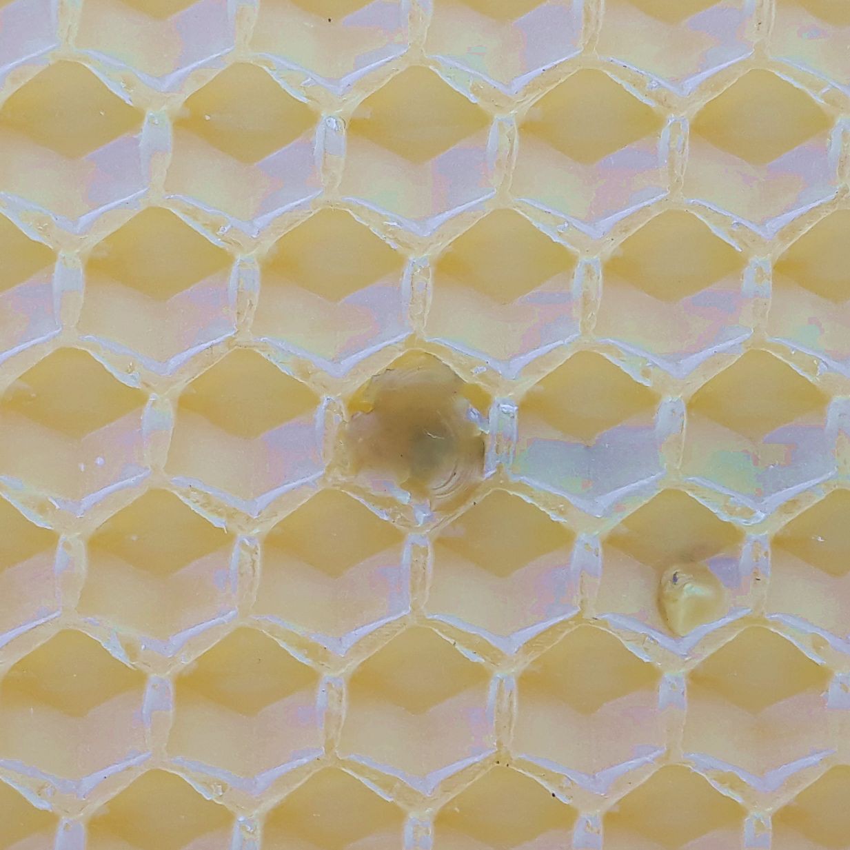
| ext. sensor size | small for hive "in cell" measurement | DESIRED | ✔ |
| memory | (timestamp + 4x temperature) * 1 year | REQUIRED | (✔) |
| easy data transfer | 3 wire interface (RX, TX, GND) | REQUIRED | ✔ |
Here's a quick jump-to to all of my log entries (latest changes are bold):
| ENTRY | LAST CHANGED |
| 01 – choice of components | Tuesday, Oct. 2nd, 2018 |
| 02 – data storage | calendar week 39 |
| 03 – test placement of components | Wednesday, Oct. 10th, 2018 |
| 04 – logger and sensor position | Saturday, Aug. 18th, 2018 |
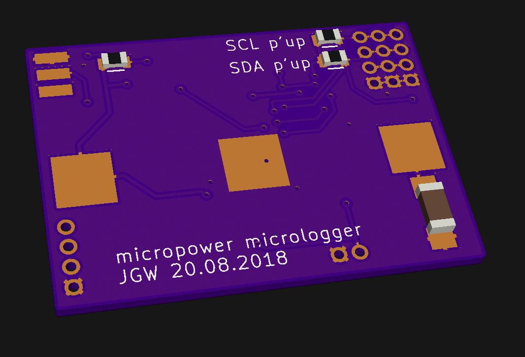
| 05 – PCB finalized | Sunday, Aug. 19th, 2018 |
| 06 – PCB finalized again and ordered | Monday, Aug. 20th, 2018 |
| 07 – shitty TMP11x breakout boards | Monday, Aug. 20th, 2018 |
| 08 – my own deadline + thoughts on suppliers | Thursday, Aug. 23rd, 2018 |
| 09 – it's alive! | Saturday, Sept. 22nd, 2018 |
| 10 – usage | calendar week 39 |
| 11 – final pictures | Saturday, Sept. 29th, 2018 |
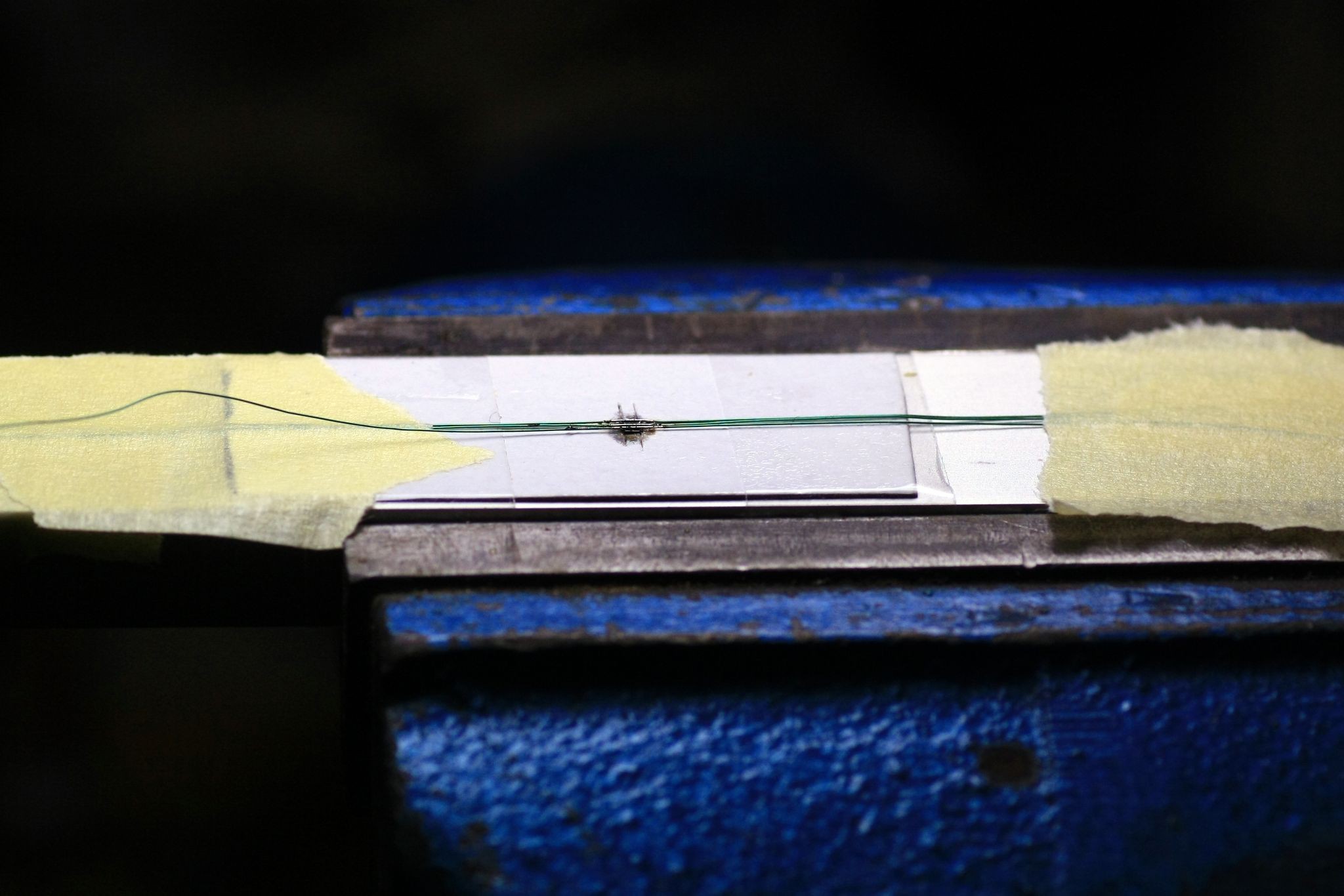
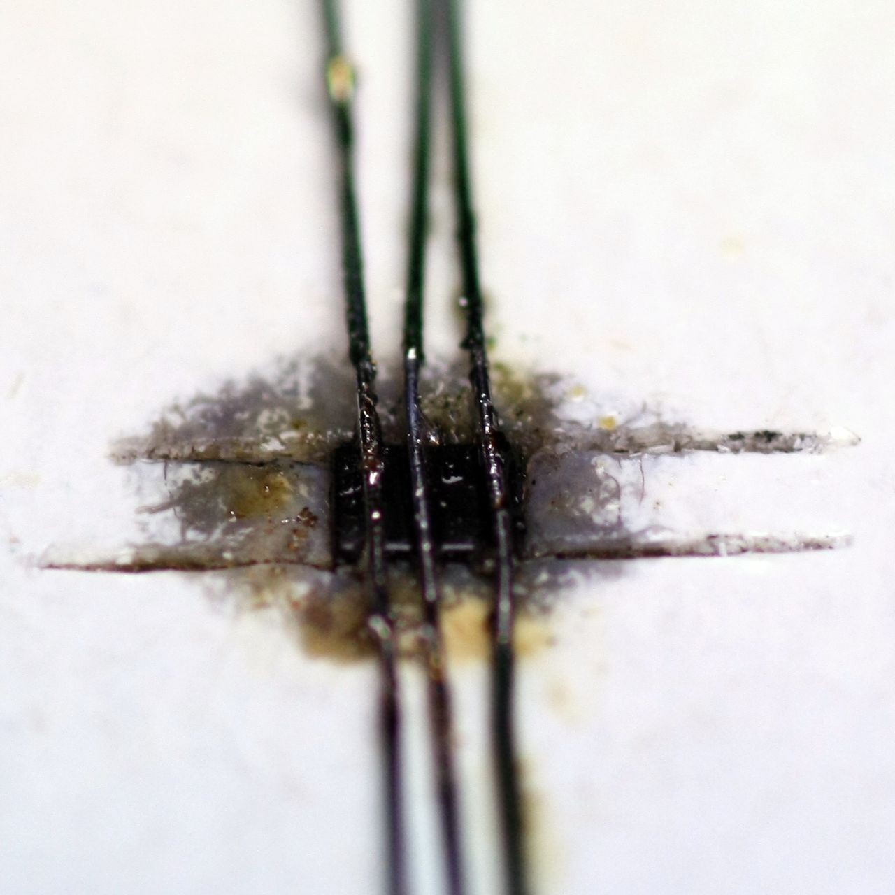
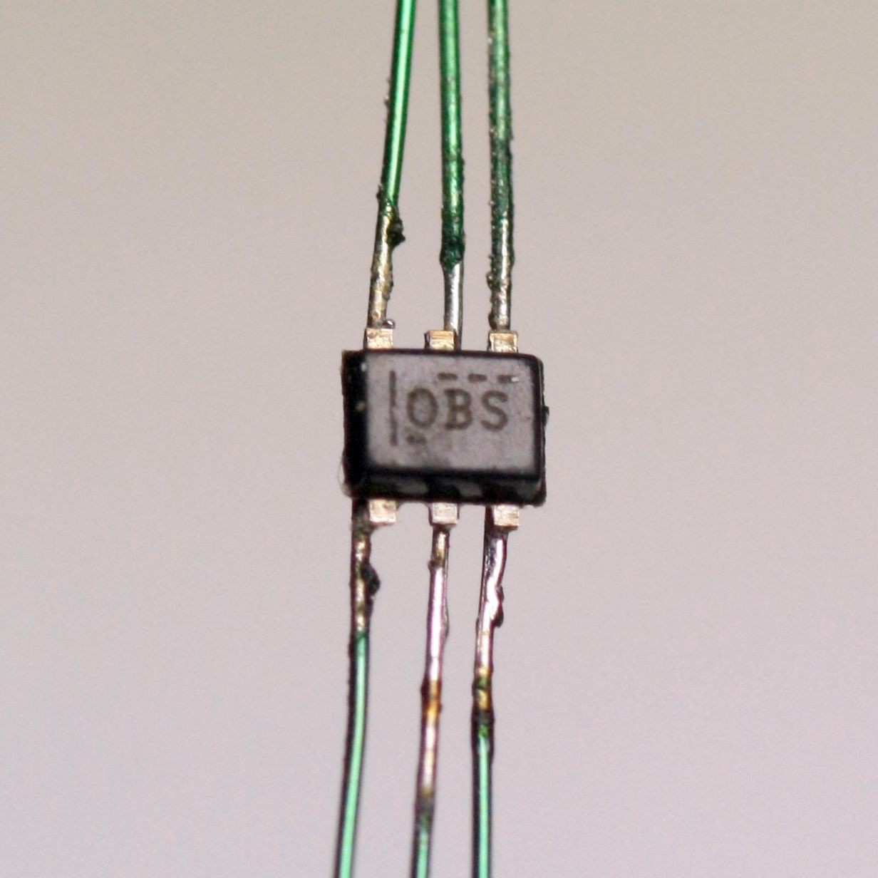
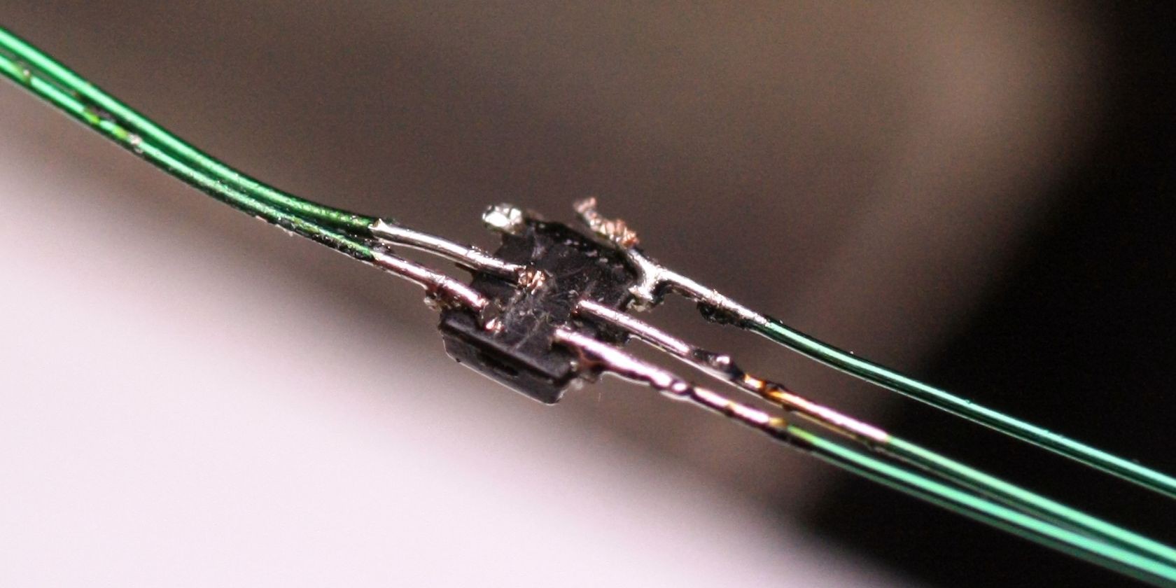
| 12 – soldering 1.6x1.6mm (SOT-563) sensors to leads | Monday, Oct. 8th, 2018 |
 HOW TO
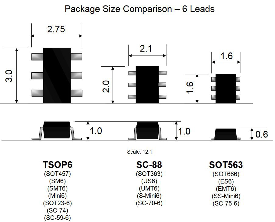


 Stephen Harrison
 deʃhipu
 Ulf Winberg
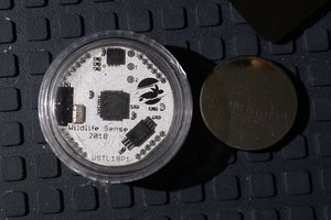
 Nikos
Nikos
Neat project and nice execution!