0%
0%
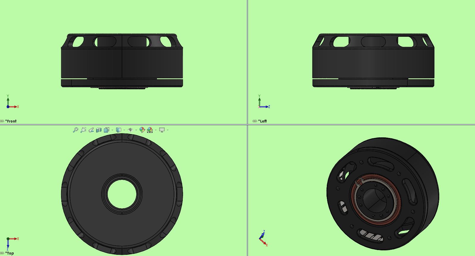
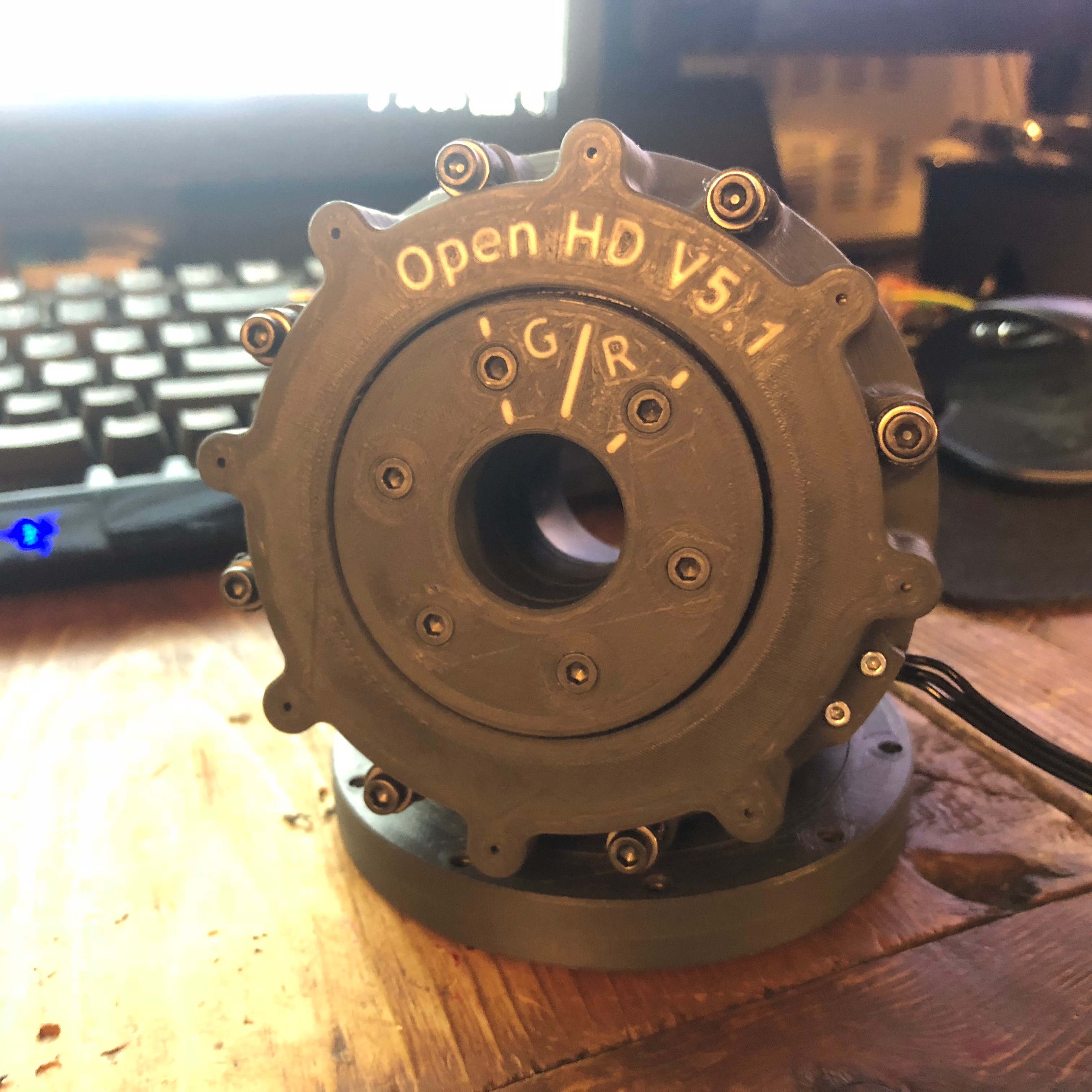
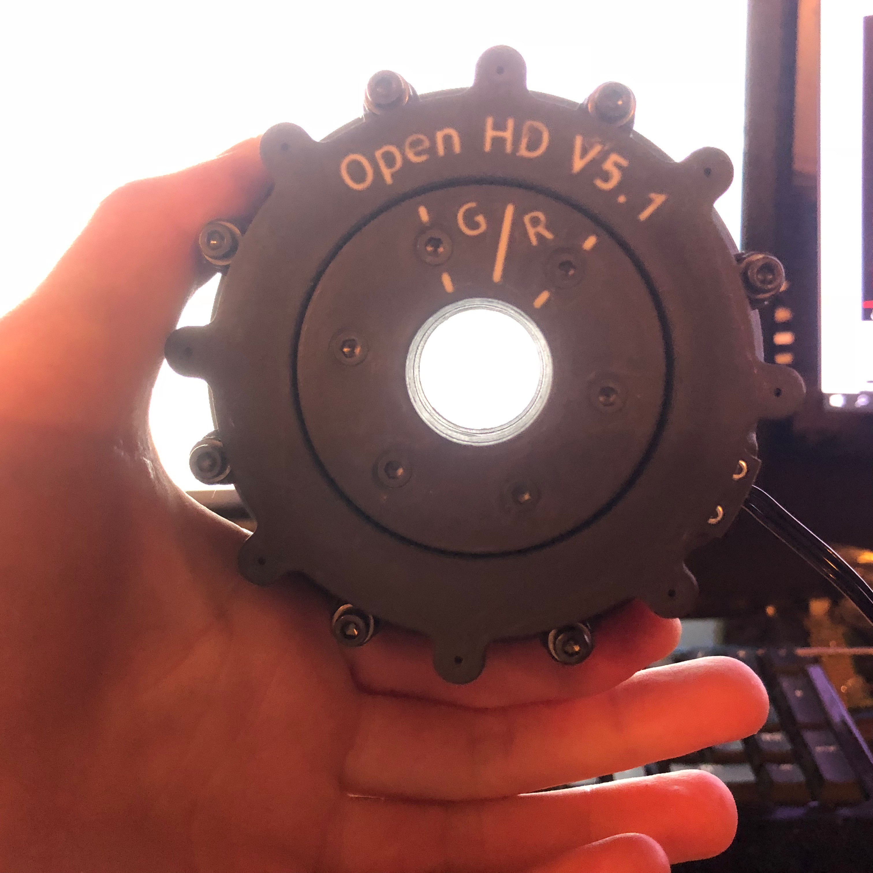
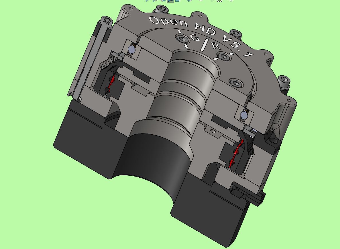
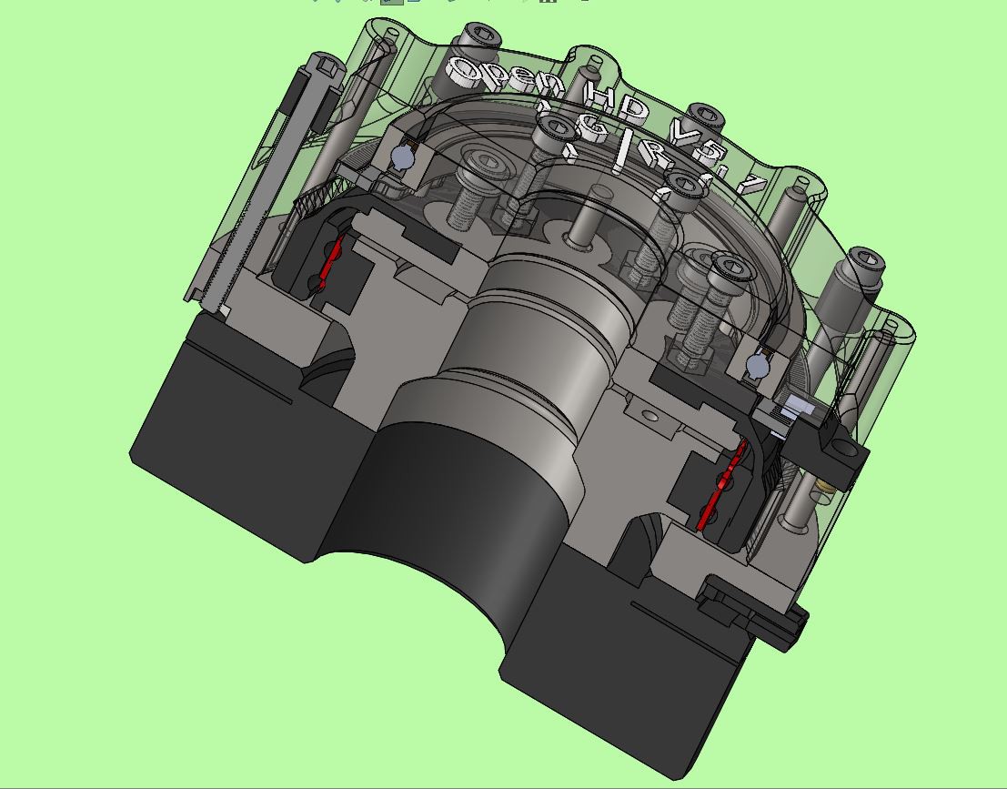
Open HD
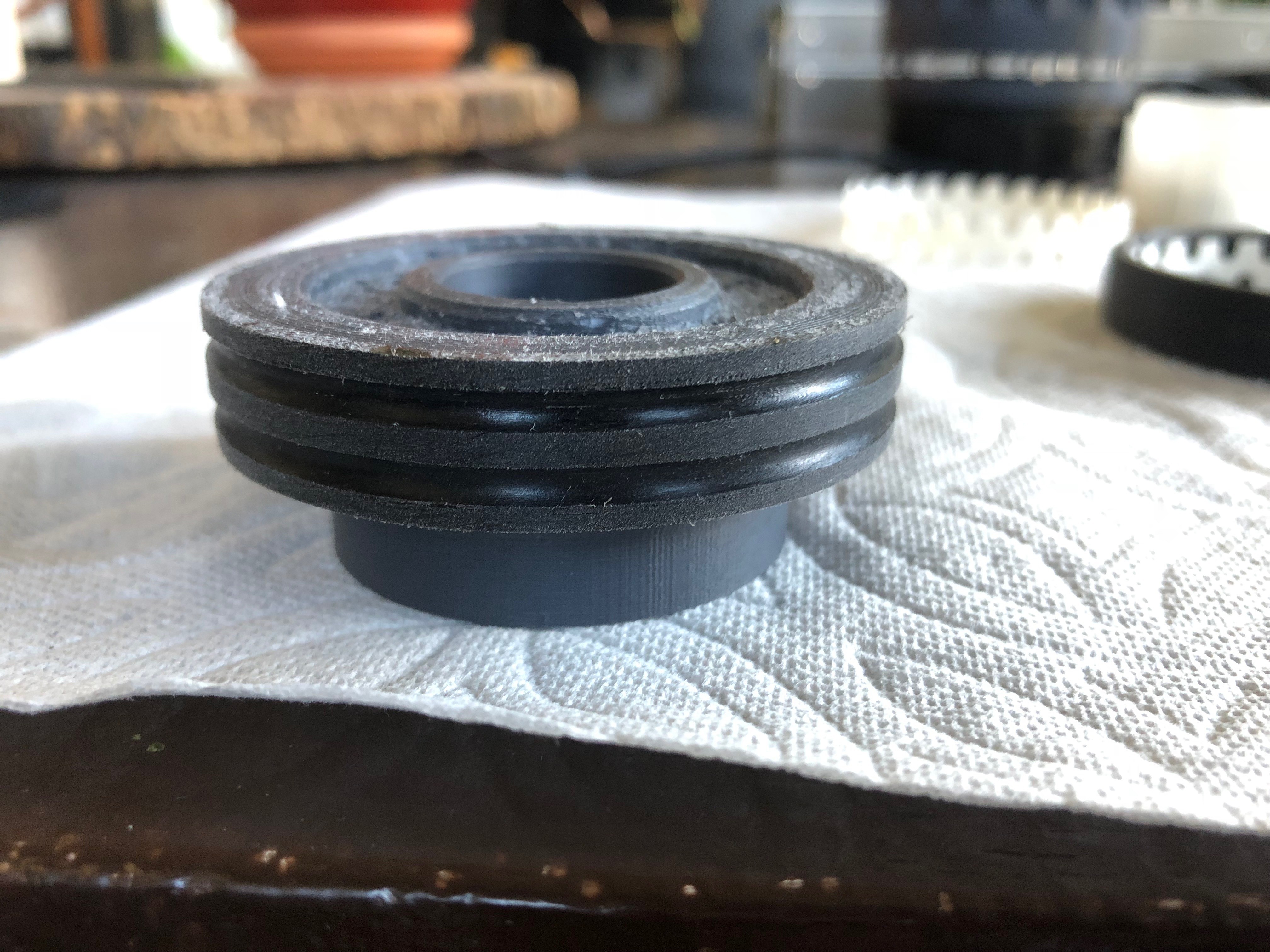
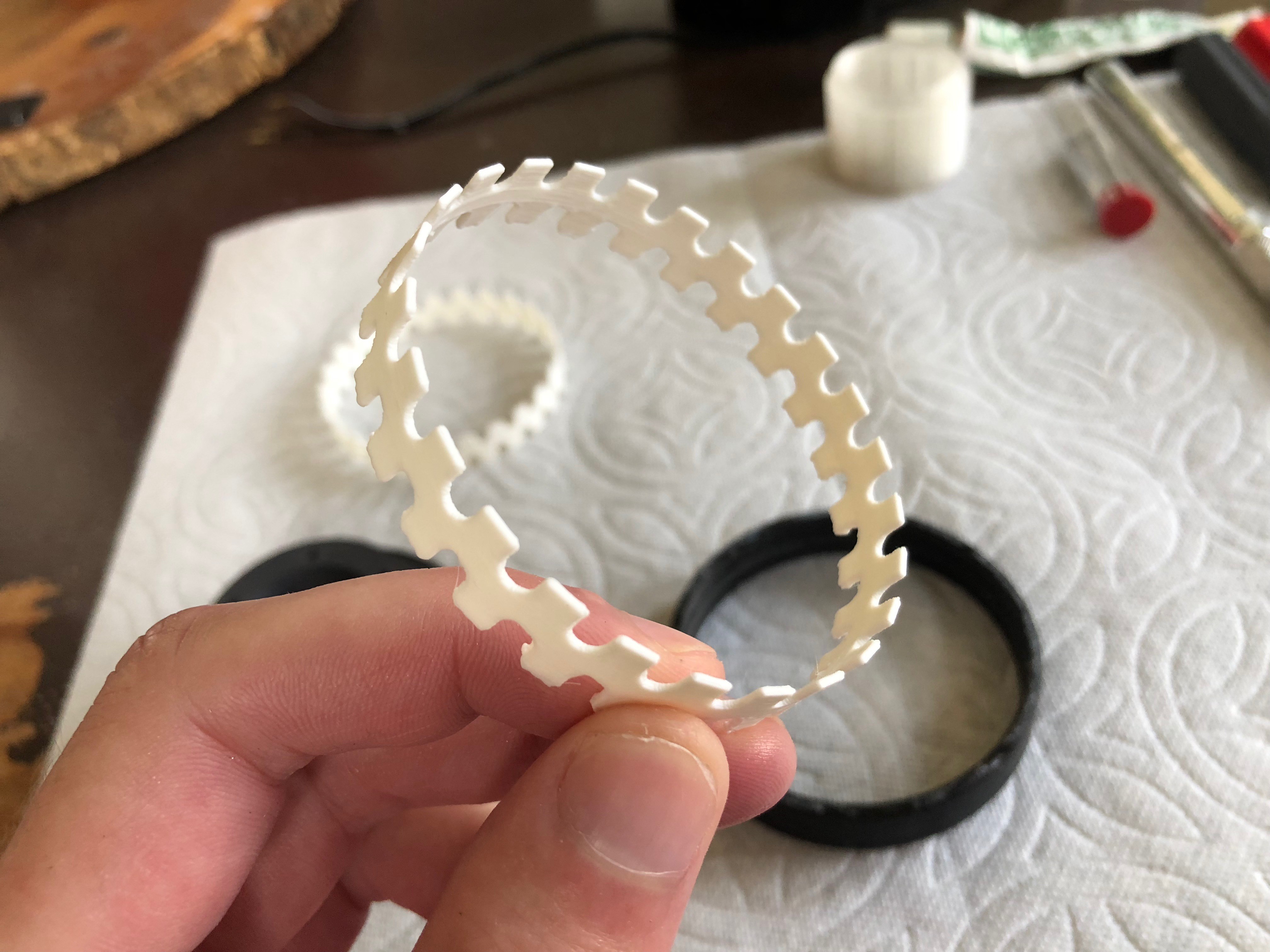
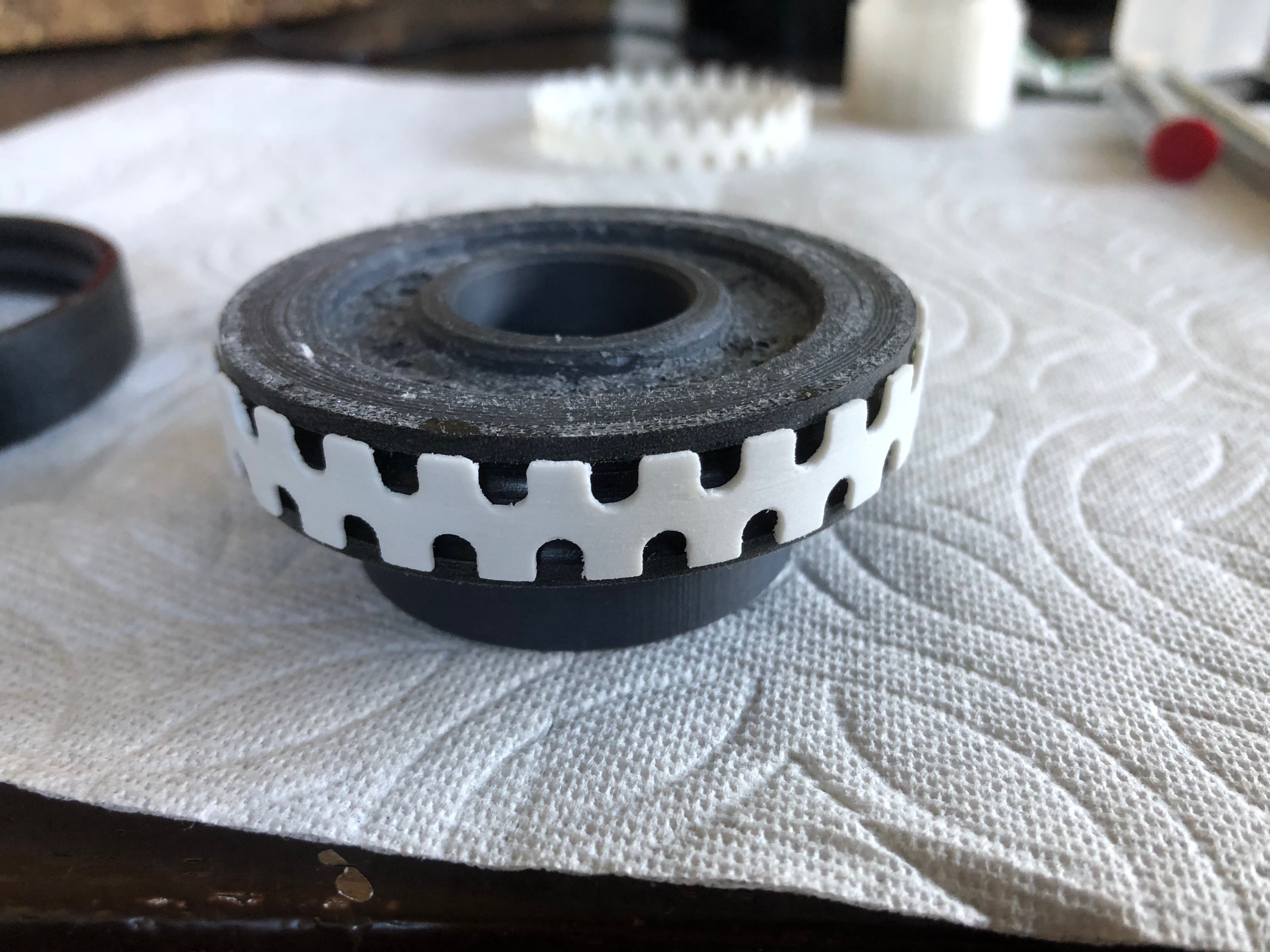
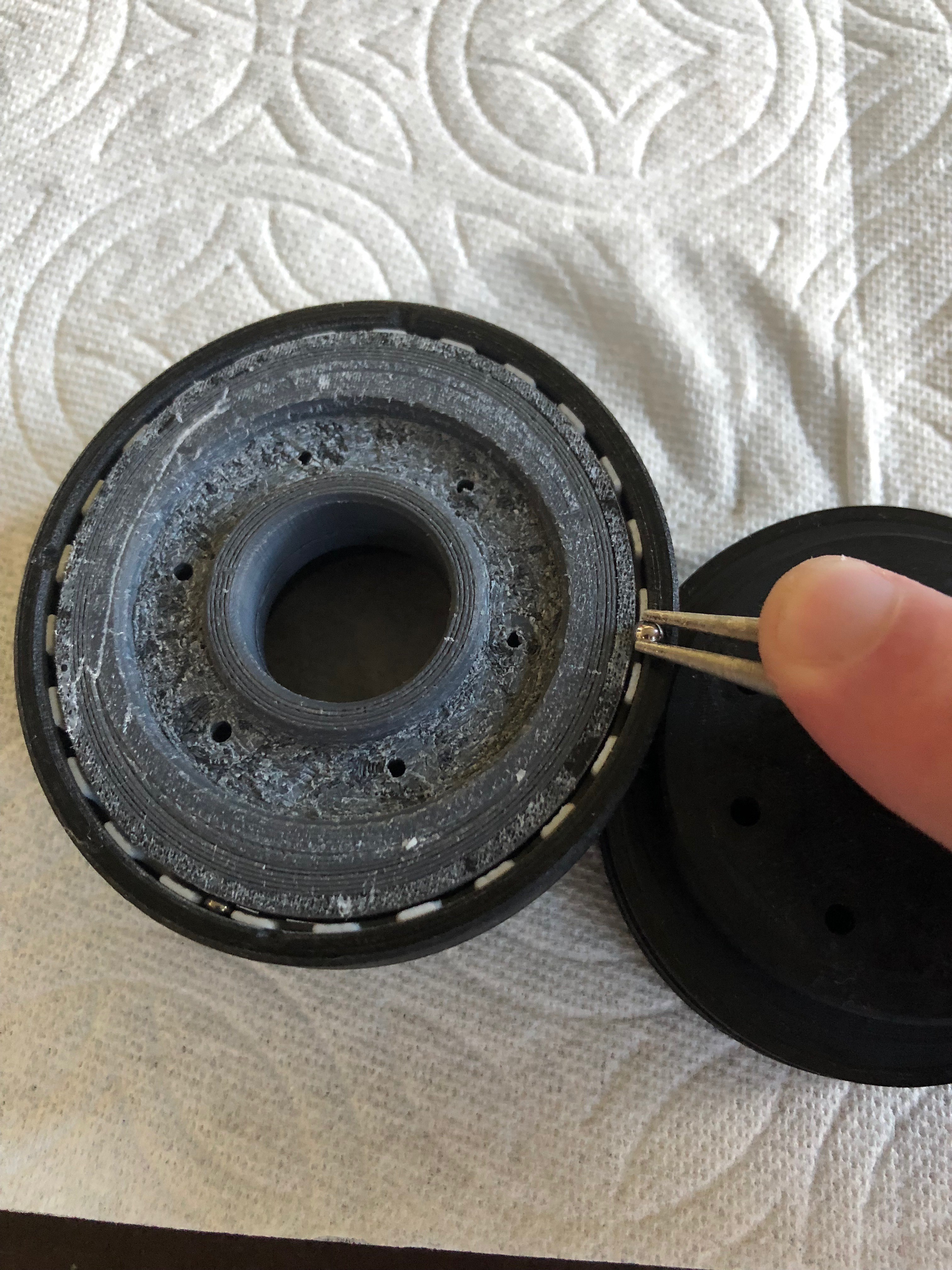
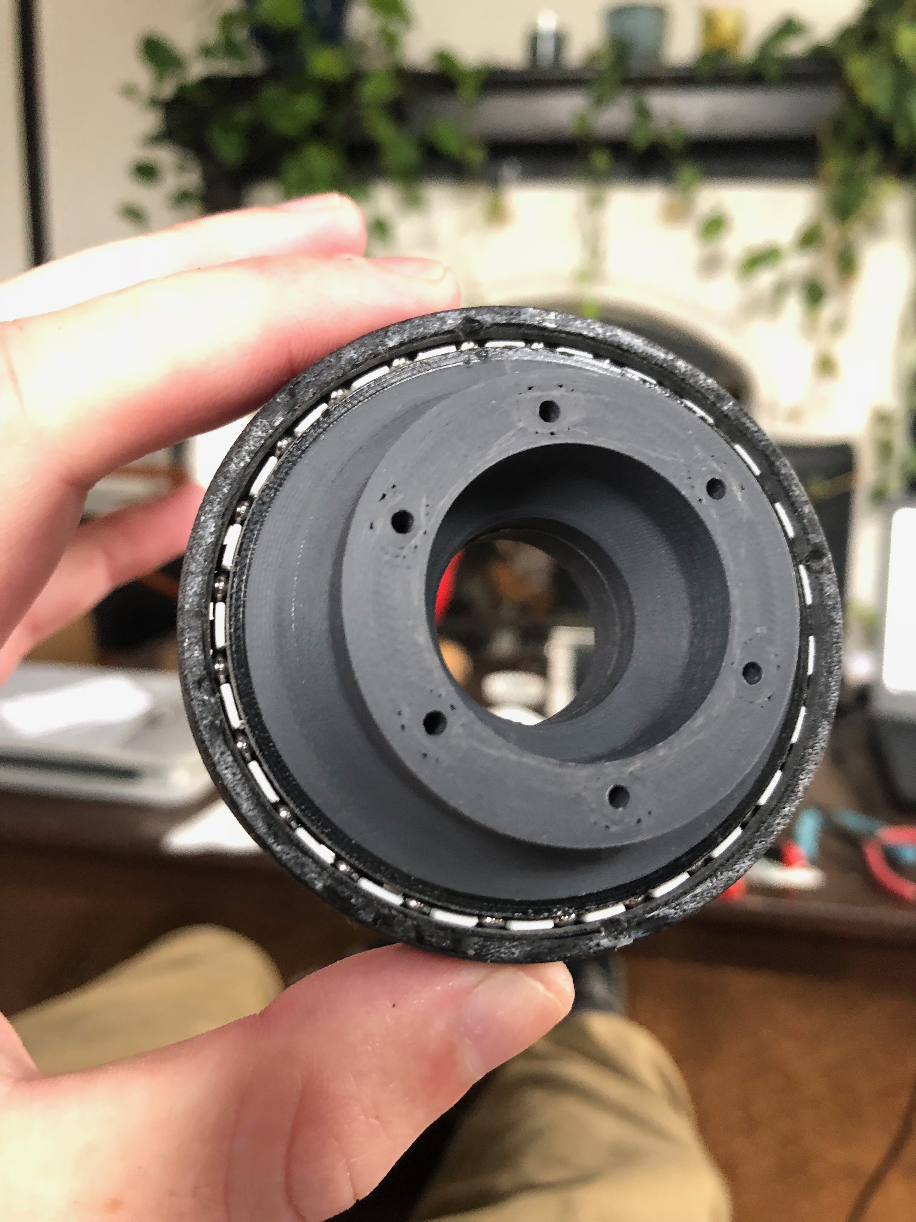
A high torque, high precision, Strain Wave Gear (harmonic drive) based 3D printable closed loop servo actuator for use in robotic arms
 Sam Armstrong
Become a Hackaday.io member
Already have an account? Log in.
Just one more thing
To make the experience fit your profile, pick a username and tell us what interests you.
Pick an awesome username
hackaday.io/
Your profile's URL: hackaday.io/username. Max 25 alphanumeric characters.
Pick a few interests
Projects that share your interests
People that share your interests


 Peter Sinclair
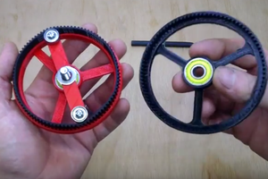
 Simon Merrett
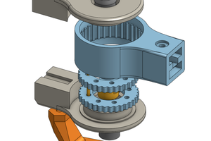
 Tim Wilkinson
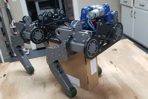
HI please provide files for the amazing project