Close
0%
0%

Tiny CAN Positioning Motor Controller

A 12A/28V DC brush motor controller with position feedback that speaks CAN-BUS... in one square inch.

Public Chat
Similar projects worth following
I wanted to see how much motor driver I could pack into one square inch... and this is the (preliminary) result. Here's the stats:

-- Brushed DC motor controller
-- Encoder feedback for position and velocity control
-- Current feedback on-board for torque control
-- CANBUS 2.0 control link
-- Up to 12A/28V output
-- Protected against overtemp/overvolt/undervolt/overcurrent

The board has components on both sides, but I still managed to keep it to two layers. It's programmable (ATTINY816), so the user can fine-tune things to their liking.

Design Brief

Since this is an entry for the Return of the Square Inch Project, the first requirement is that it must fit into one square inch. The challenge then is to get as much power into that square inch as possible. Other requirements are as follows:

  • Must drive brushed DC motors
  • Must communicate with CAN 2.0
  • Must be capable of current feedback control
  • Must be capable of velocity feedback control using an encoder
  • Must be capable of position feedback control using an encoder
  • Must be programmable with tools I have on hand and already know how to use (pretty much means AVR or ARM)
  • Must have mounting holes

This means that I need to use surface mount parts, some sort of microcontroller, and SMD parts with the highest level of integration I can get. It also means I'll need an encoder interface. Since I've already been playing with some parts for a line of CANBUS nodes I've been noodling, I already had some parts in mind.

Parts Selection

MCP25625 CANBUS Interface

This is essentially two chips stuffed into a single package -- the MCP2515 CAN controller and MCP2551 CAN driver. That pair is the heart of the typical hacker/maker/hobbyist/etc CAN interface board, including the offerings from Sparkfun and Seeed. The host microcontroller talks to it via SPI and it does all the protocol stuff. Combining the two chips into a single chip saves a bunch of board space and routing, as well as a bit of money. It requires a crystal or resonator, and provides a clkout line that allows us to drive the clock on the host microcontroller.

The driver and logic sides of this chip have different power supplies. The driver requires 5V but the logic side can go from 2.7V to 5.5V. Since we're trying to keep things small and tidy, we'll hook both power supplies up to 5V.

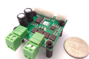
BTM7752G DC Motor Driver

This chip is the real star of the show, and takes up more space than all other chips put together. It's a 12A/28V driver with all the protection (overtemp/overcurrent/overvolt/undervolt) you'd expect. The user has direct control over both half-bridges and a global enable. Current feedback and fault annunciation share the same line. It's as big and simple a lump of power silicon as I thought I could fit on the board.

ATTINY816 Microcontoller

This is the brains of the operations. It's not one of the typical ATTinies seen in maker & hacker projects because it's not yet supported by the Arduino IDE. It has a lot of nice features over the other ATTinies; for this project the most important are the improved PWM, improved ADC, and more flexible interrupts for interfacing with the encoder.

Power Arrangements

A 5VDC LDO hooked into the main motor power drives the logic. I found a cheap three terminal LDO in SOT-23 form factor.

Connectors

This is the place where the size restrictions bite the hardest. The power input and output connectors are just areas of bare copper on the board you can solder wires to. Not the best, but hard to do better in a square inch.

The logic connectors (CAN, ICSP, and encoder) are all JST SH series. They're tiny and I'm already familiar with them from the Beaglebone Blue.

Software Arrangements

The typical way a position controller works is three nested loops -- current control, velocity control, and position control. For truly excellent motion control, you can add acceleration control to tame jerk. This reduces vibration in machines, but is a bit beyond this project. Similarly, the loops will all be standard issue PID loops with no feed forward terms. That limits their ultimate performance but keeps the software task in bounds for a contest that closes in a few weeks.

The gating item is the PWM frequency, which is limited to 25 kHz by the motor driver chip. With a 16 MHz main clock, this gives me 640 duty cycle steps, which is more than enough here. Ideally, the current loop needs to run about an order of magnitude slower than this for stability, or about 2500 Hz. We'd like the outer...

Read more »

gbr - 1.58 kB - 10/01/2018 at 15:04

Download

gbr - 2.39 kB - 10/01/2018 at 15:04

Download

gbr - 1.62 kB - 10/01/2018 at 15:04

Download

gbr - 2.66 kB - 10/01/2018 at 15:04

Download

gbrjob - 341.00 bytes - 10/01/2018 at 15:04

Download

View all 11 files

  • 1 × ATTiny816M Microcontroller
  • 1 × MCP25625ML SPI to CANBUS interface
  • 1 × UUR1V101MC6GS 100 uF 35V SMD electrolytic capacitor
  • 6 × 100 nF 50V 0603 capacitor generic part
  • 2 × 100K 0603 resistor generic part

View all 14 components

  • Project Wrap-Up

    Pierce Nichols10/01/2018 at 15:23 0 comments

    So... I wasn't ultimately able to get past my soldering issues so I wasn't able to get any of the boards working to the point where I could start writing and testing software. I think the problem was that I included a via connecting the ground pads of the uC and the CAN interface together, which was enough to push the solderability over the line of what I am capable of doing.

    I was, however, able to get the basic requirements of the contest (gerbers, pictures of assembled project, and parts list) together in time.

    This was sort of a practice run at something I've been thinking about since Toorcamp this year, which is a line of cheap, single-function CAN interface boards. I.e. something like this board plus various sensor and actuator interfaces. The boards will be bigger (1 x 2 inches) and all the components will be on one side. There's a nice low-end STM32 chip that has built-in CAN which I expect to use as the heart of that line of boards. I'll be opening a new Hackaday.io project to hold that. Here's my preliminary line-up:

    • DC brushed motor controller
    • 9-axis IMU
    • 4 ch 24 bit ADC with programmable gain amplifier & onboard temperature sensor
    • SPI & I2C interface with proto area
    • Stepper motor controller (probably a RAMPS carrier with feedback provisions)
    • Servo output
    • DAC output
    • GPS
    • High current DC switches

  • One step forward, one step back

    Pierce Nichols09/26/2018 at 05:32 0 comments

    My day job has owned most of my headspace this month, so I've just gotten to the point where I have my three boards assembled and powered up. The good news is that none of them show any sign of shorts or any similar problems. The bad news is that not a single one responds to the programmer... and probing around makes it look like none of the reset lines got connected when I soldered down the processors. I don't think my hands are steady enough at this hour to fix it, so I will give it a swing tomorrow.


    I did manage to get the CAN interface library ported to C and compiling, so I'm not quite out of the running yet. I'm not entirely confident of my ability to get beyond current control in the time I have left, but we will see.

  • Oh goody...

    Pierce Nichols09/06/2018 at 07:40 0 comments

    It appears that in order to get one of the existing MCP2515/25625 libraries to play nice with the ASF drivers in the project created by Atmel START, I need to port it over to plain C. This isn't completely horrible, since the one I picked mostly just use C++ for encapsulation and I'm not trying to run multiple chips. Still a pain in the neck to refactor, and I'm not entirely sure how to set up Atmel Studio to suck in the files in any way that does not involve just copying them in.

    In better news, I think I have my configuration finished, and I think I found a way to use the event system to use Timer/Counter B to capture the time of each encoder pulse. That wraps up way too much hemming and hawing just in time for the boards to show up. One possible wrinkle, however, is that the pulses off the edge detector as built are very short as it uses the main clock to drive the clock input of the flip-flop. Therefore, I am not 100% sure it will capture all pulses and I won't have the opportunity to find out until I have the boards in hand and assembled.

  • New boards ordered

    Pierce Nichols09/02/2018 at 21:08 0 comments

    Ok, got the new boards ordered, expect them by Friday. Pictures of the new design are up and I've pushed it to Github. I decided to take the opportunity to fix my encoder issues with an external edge detector circuit.

  • Never too smart to make a dumb mistake...

    Pierce Nichols09/01/2018 at 17:19 0 comments

    I got the boards back from OSHPark's swift service... and discovered that I had made a dumb mistake. I used someone else's QFN-20 footprint (because lazy/in a hurry/etc) and discovered that it is entirely the wrong size. So this spin of boards is junk... luckily it's only $10 (one of the advantages of the limits of this contest) so I'm mostly just out the time. I also found that I'd forgotten to order the resonators, so there's that too. I guess next weekend is going to be a bit of a sprint; luckily OSHPark will be able to get me boards in time.

    However, this gives me the opportunity to revisit an earlier issue, which is adding external logic to give me a nice pulse on each encoder transition. Turns out I can find places for the parts, and since I need to order both boards and parts already, it's an easy decision to make. New pictures and board files will go up tonight or tomorrow.


  • More (en)code(r) fun

    Pierce Nichols08/29/2018 at 06:25 0 comments

    My components have arrived and my boards have shipped... so I'm continuing to bang my head against the encoder problem in the meantime.

    As an aside, this process of poking around has been greatly helped by the configuration tools at start.atmel.com, which give you a way to configure all the libraries and peripherals you need for your AVR or Atmel ARM project and export the setup code as an Atmel Studio project ready to go. Since the '816 is significantly different than earlier ATTinys, this has been a huge help in getting me up and running and futzing around with peripherals.

    I can certainly capture every other transition easily enough -- configure LUT0 as an XOR on the two phases and feed it into one of the event lines and drive the capture input of one of the timers from there. But I could do twice as well so I'm spinning my wheels a bit.

    If I feed the output of LUT0 and the output of the optional D flip-flop into LUT1 and configure it as another XOR, I should get a one clock cycle pulse on the output of LUT1 -- enough to clock the flip-flop and trip the counter. I tried doing this with the outputs of LUT1 and the DFF fed out to two I/O pins, but I did not see any evidence of output using my logic analyzer.

    My next trick is to hook up an interrupt to the counter capture so I can toggle a pin every time the counter capture fires... and this isn't firing at all. That troubles me more than almost anything else because if I can't get that hookup to work it means that I'm SOL on getting any help from the CCL on making the encoder work better than I get from just hanging pin change interrupts on the two input lines.

    The encoder I've been using for testing (a super cheap thing designed for panel controls) has some mechanical bounce to it, which means I have a way to judge the minimum time to sample a single edge.

    The first time I tried this, the results were awful -- 3-4 us of delay from a transition to the pin toggle I attached to the interrupt. Then I realized I'd left the clock prescaler turned on. Once I turned it off, I'm clocking a very consistent 720 ns from incoming edge to toggle. Since I anticipate a minimum time between transitions of ~33 us, this is good enough for a passable velocity controller.

    So enough about that problem and on to the next one.

  • Components ordered, more encoder musings

    Pierce Nichols08/24/2018 at 06:47 0 comments

    I ordered the components and they should be here early next week.

    I'm expecting an ATTiny817 dev board tomorrow, so I can start messing around with the CCL and the encoders. I am currently not seeing a way to get the signal I want (rising edges on every transition) without at least one extra component. I think I might be able to make it work with a single off-board gated D flip-flop (DFF) and both LUTs configured as XORs based on this dual edge detector circuit from Cypress (at the bottom). LUT0 would XOR the two phases together, generating a single signal with an edge for each transition, and pass it out an I/O pin to the offboard DFF. The output of that would pass back to LUT1 through an I/O pin, where it would be XORed with the output of LUT0, generating a rising edge on every transition, perfect for feeding to one of the internal timer/counters.

    That feels like admitting defeat. Also, I'd have to do a third board spin (!!) before I assembled the first one, which is not really the way I want to roll.

    So... I think I'm going to do this the dumb way. I'll set TCB as the timer for my main loop and set up TCA to track the cycles since the start. I can then make both of the phase inputs interrupts, and use the current value of TCA to track how long its been since the last transition. We'll see how well this works in practice.

  • Second round of boards & encoder fun

    Pierce Nichols08/22/2018 at 15:47 0 comments

    Turns out I made a mistake and never ordered the first round of boards. It's an irrelevant oops, since I would have just had to scrap them on arrival.

    This morning I ordered new boards with the super-swift service from OSHPark. I thought about going with the 2 oz copper instead, but since the high current traces on this board are so broad and short, I can go without the heavier copper and I want my boards stat. I haven't bothered uploading new pictures yet, because almost all the changes are with traces and aren't particularly visible on board level images.

    There is one change of note, and that's that I went to a three pin programming header. The ATTiny816 is designed to be programmed through the reset line alone, not through the SPI port like previous generations of AVRs. This lets me switch to an 0.1" pitch programming header, which means less futzing with wires and more just plugging the thing into my programmer.

    I also ordered an ATTin817 Xplained Mini and a couple of encoders for delivery Friday, because I am not having a great time figuring out how to make the encoder logic work the way I want it to.

    A quadrature encoder has four state transitions per pulse. That means that you can, in principle, quadruple the resolution of a given encoder by taking measurements at each transition -- a 48 pulse per revolution encoder now counts 192 times per revolution with just a bit of software. However, this is a bit more difficult in practice.

    The most straightforward way to approach this is to connect each phase of the encoder to a separate interrupt pin, set them to transition on rising and falling edges, and use a timer to measure the times of transition. This is fine as far as it goes, but is subject to jitter if there are any other interrupts in the system, such as a main loop timing interrupt, and depending on how interrupts are scheduled, may result in some steps being dropped entirely. That jitter doesn't matter much if you are controlling only position with no velocity control or differential terms in the control loop. However, we will be controlling velocity, and the noise in the velocity measurement caused by jitter is to be avoided. So we're going to take a somewhat harder road.

    There are two subsystems/peripherals that make it possible to do something better with the '816. The Timer/Counter B has a frequency measurement mode that copies out the counter value and fires an interrupt on the rising edge of a single input. That would not be enough by itself without some off-chip glue logic, but the '816 has something called Configurable Custom Logic (CCL) on the chip.

    The CCL has two configurable three input lookup tables (LUTs). They can be configured to any of the 256 possible three input logic truth tables. Two of the inputs of each LUT can come from input pins -- if you remember from the last update, phases A & B of the encoder are wired to the inputs of LUT0. Each LUT has an optional filter and an optional rising edge detector. The outputs of the two LUTs may optionally be connected to a sequential logic element -- either a JK flipflop, a D flipflop, a D latch, or an RS latch. Finally, the output of the sequential logic element can be fed back to either LUT, and each LUT can also take the output of the other LUT as an input.

    I'm reasonably certain that somewhere in all this is a way to create what I really need, which is an internal signal that provides a rising edge on each transition of the two input pins. Tonight I will draw it out and post further.

  • Rerouting all the signals

    Pierce Nichols08/15/2018 at 04:55 0 comments

    So, it appears that I stuffed up the routing of the signals into the ATTiny816 on my initial design... time to re-do it, right this time. Here's a quick overview of what I need to connect

    • Clock input from the CAN interface
    • Reset/programming line
    • SPI (CS, MISO, MOSI, and SCLK) to the CAN interface
    • Two complementary PWM outputs to the motor
    • A, B, and Z lines from the encoder
    • One analog input from the motor
    • Interrupt line from the CAN interface
    • Reset line to CAN interface
    • One enable line to the motor

    Forced Allocations

    Three of these can only go to particular pins.

    • The reset/programming line is PA0 (pin 19). One of the advantages of the ATTiny 816 is that it is designed to be programmed and debugged via the reset line alone; this makes the programming header much more compact, since the rest of the SPI interface does not need to be connected as it is with earlier AVR parts.
    • The clock input must go to PA3 (pin 2)
    • There are two options for SPI on this part, but the default option (PA1-4) overlaps the clock input, so we must use the other option, which is PC0-3, or pins 15-18.

    Timer/Counter Allocations

    There are three functions in this design that require timer/counter services (timer interrupts, PWM, and encoder input), and only three timer/counters on the chip. These timer/counters are connected to a fairly limited set of pins. 

    Allocating the PWM is simple, because Timer/Counter D has specific functions for generating complementary PWM signals with configurable deadband and other features particularly useful for controlling motors. It has four output pins -- PA4, PA5, PC0, and PC1. Since PC0 and PC1 are already allocated to the SPI, PA4 & PA5 are allocated to PWM.

    The encoder is a bit trickier, because I want to count both the rising and falling edges of phases A & B of the encoder in order to quadruple the number of counts per revolution. The timer/counter peripherals are only able to count on a single channel. Luckily, the ATTiny816 provides configurable custom logic (CCL) to enable me to get around this limitation. The XOR of phase A & B will transition on every edge, and the CCL provides the ability to do this. Unfortunately, there are only two available CCL input pins still available, PA1 & PA2, so they are allocated to encoder phases A & B. Since only Timer/Counter B offers a frequency measurement mode, the encoder is allocated to Timer/Counter B.

    This leaves Timer/Counter A to generate the timer interrupts that drive the control loops

    Other Allocations

    The analog input from the motor must go into one of the analog pins, which are PA0-7, PB0-1, and PB4-5 on the '816. In order to limit the amount of re-routing, we'll allocate PA6 to motor current feedback.

    Phase Z of the encoder fires once per revolution to provide a more absolute position signal. One of the nice features of the '816 is that any pin can be used as an interrupt, so we'll leave it where it is (PB3)

    The motor enable line can go anywhere, so we'll move it the shortest distance available, to PA7.

    The CAN reset and interrupt lines can go anywhere, so we'll allocate them to PB0 and PB1.

    All of these allocations are subject to change for routing convenience. Here's a handy table:

    Pin NamePin (QFN)Function
    PA019Reset/UDPI
    PA120
    Encoder Phase A
    PA21Encoder Phase 2
    PA32Clock Input
    PA45Motor PWM 1
    PA56Motor PWM 2
    PA67Motor Current Sense
    PA78Motor Enable
    PB014CAN reset
    PB113CAN interrupt
    PB311Encoder Phase Z
    PC015SPI SCK
    PC116SPI MISO
    PC217SPI MOSI
    PC318CAN CS

  • Uh-oh

    Pierce Nichols08/14/2018 at 15:03 0 comments

    Whelp... turns out that I stuffed up the pinout and need to re-route and re-spin so that the Timer/Counter channels and so on are hooked up in the correct places. This thing was a pain to route in the first place -- so much fun to do it again!

    Since this project uses three different timer/counter peripheral functions (PWM, timer interrupts, and encoder input), I need to be pretty careful about how I use the peripherals.

View all 10 project logs

Enjoy this project?

Share

Discussions

Similar Projects

Does this project spark your interest?

Become a member to follow this project and never miss any updates