Sensor & Other :
- Toshiba TCD2700
- 3x 7500 Pixels for RGB
- 60mm optical area
- 40mm scanning movement
- 60x40mm image -> 37.5 MP resolution
Github with Files: https://github.com/heye/scan_cam
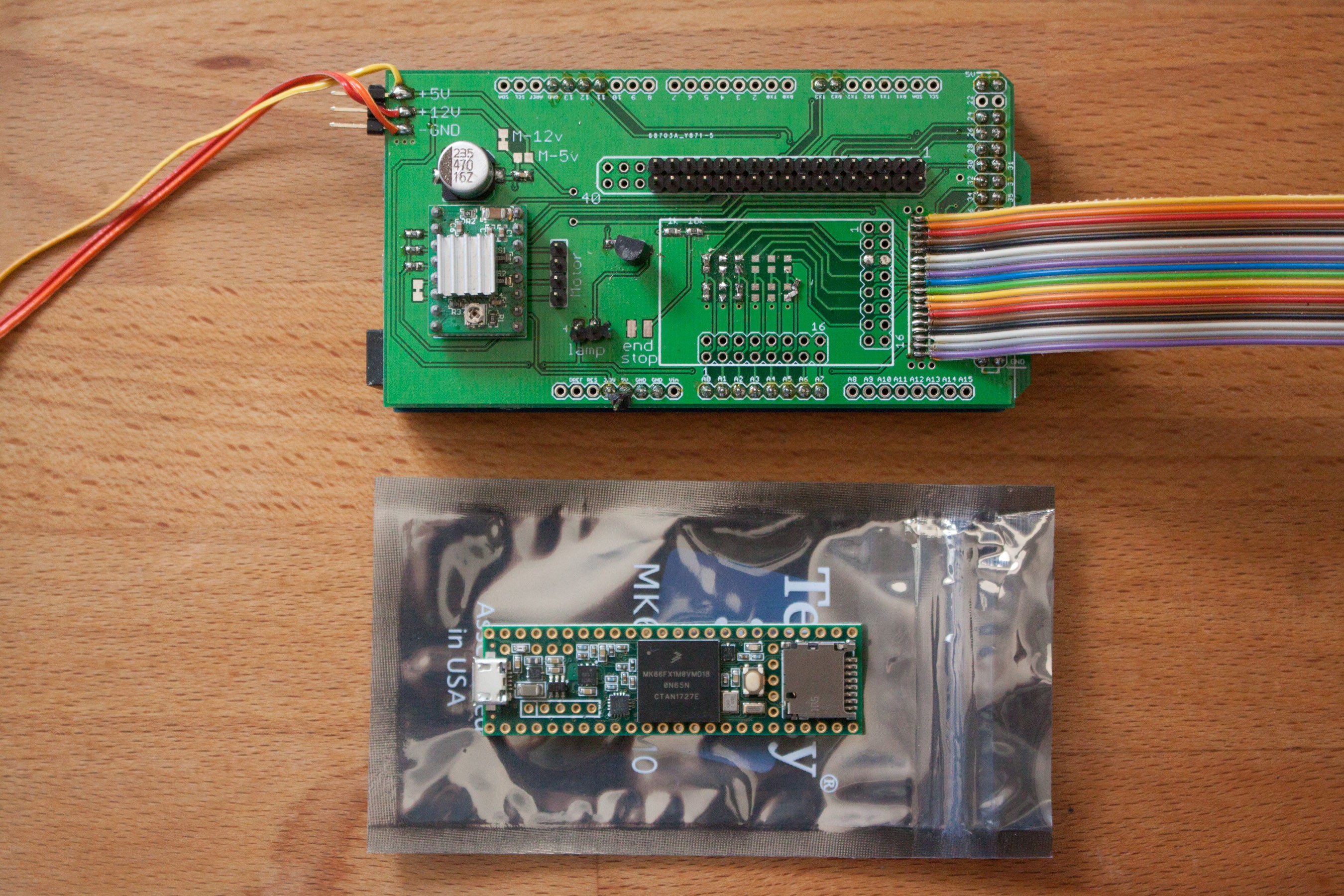
Based on a large (60mm) linear CCD I want to build a digital back for a medium format camera. A Teensy 3.6 will be used as main electronics.
Already have an account? Log in.
To make the experience fit your profile, pick a username and tell us what interests you.
Sensor & Other :
- Toshiba TCD2700
- 3x 7500 Pixels for RGB
- 60mm optical area
- 40mm scanning movement
- 60x40mm image -> 37.5 MP resolution
Github with Files: https://github.com/heye/scan_cam
After the initial results with only one color channel looked good I wanted to see what happens when I read all 3 color channels and put them in a picture.
First the electronics had to upgraded and all color channels connected to the arduino. Then the software got a complete rewrite, since managing the hacked together code from the first examples got more and more complicated. The file format got changed as well from a text file to a binary file. This reduces overhead a lot (previous Image Size at 1/4 resolution was 73MB and that is only grayscale! With RGB colors I now get the same image size)
So after a lot of coding and a lot of testing and a lot of weird errors that happen when you try to process binar data I got to the point where I could get a first color-test scan.
I used my phones LCD as a light source, made a slow scan and changed the color while scanning. This was looking very promising.
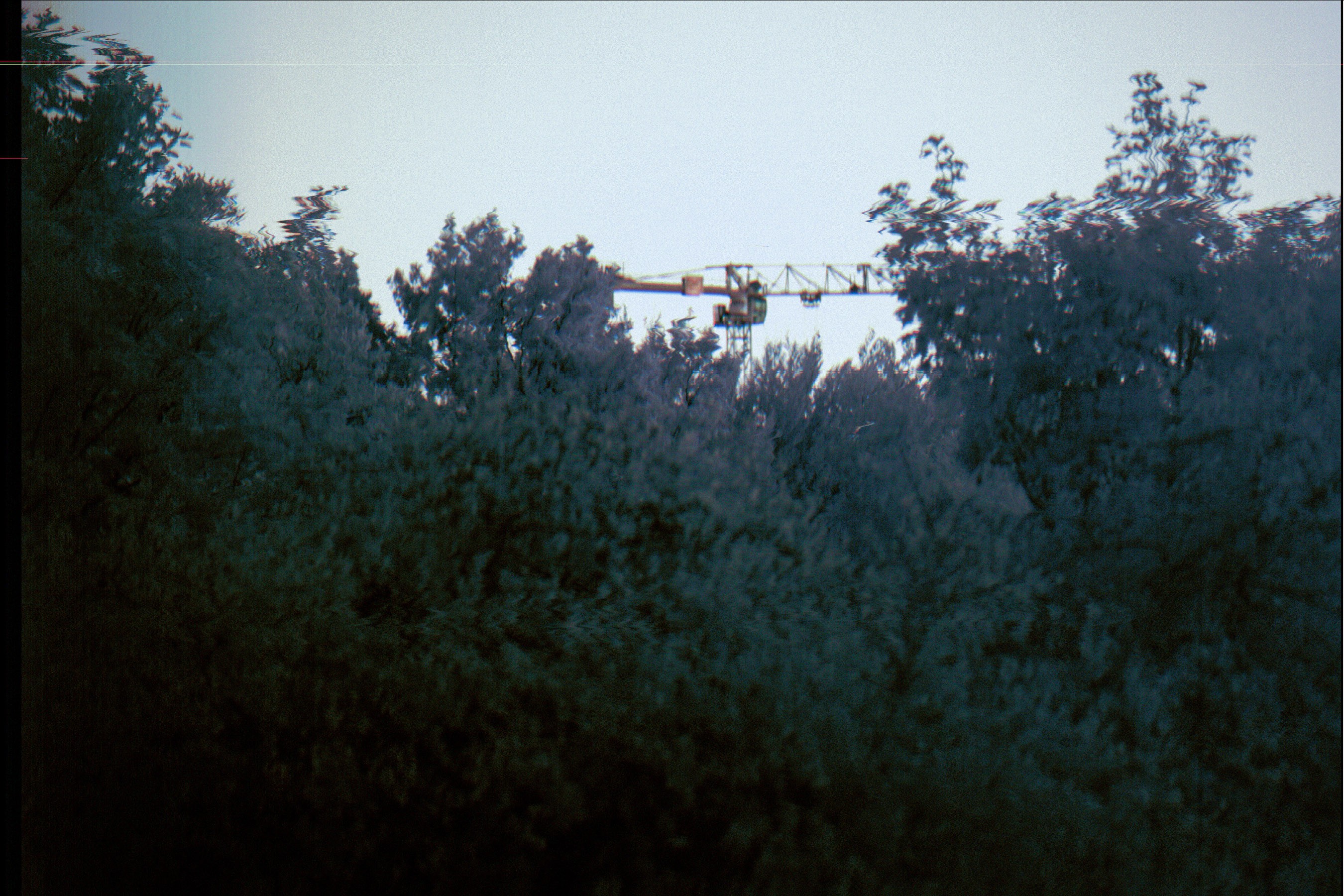
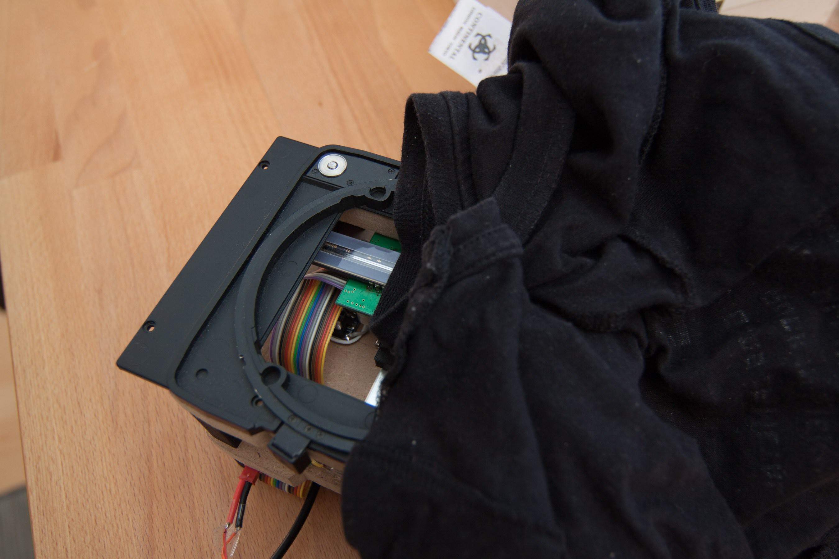
To increase image quality and to make testing a lot easier I sealed the sensor part of the scanner with black foam board and black tape. There were a lot of problems with weird sensor readings and I suspected that the t-shirt I used to hang over the scanner didn't make a very good seal.
The ribbon cable feedthrough was also sealed with black foam that is usually used for light seals in analog camera repairs.
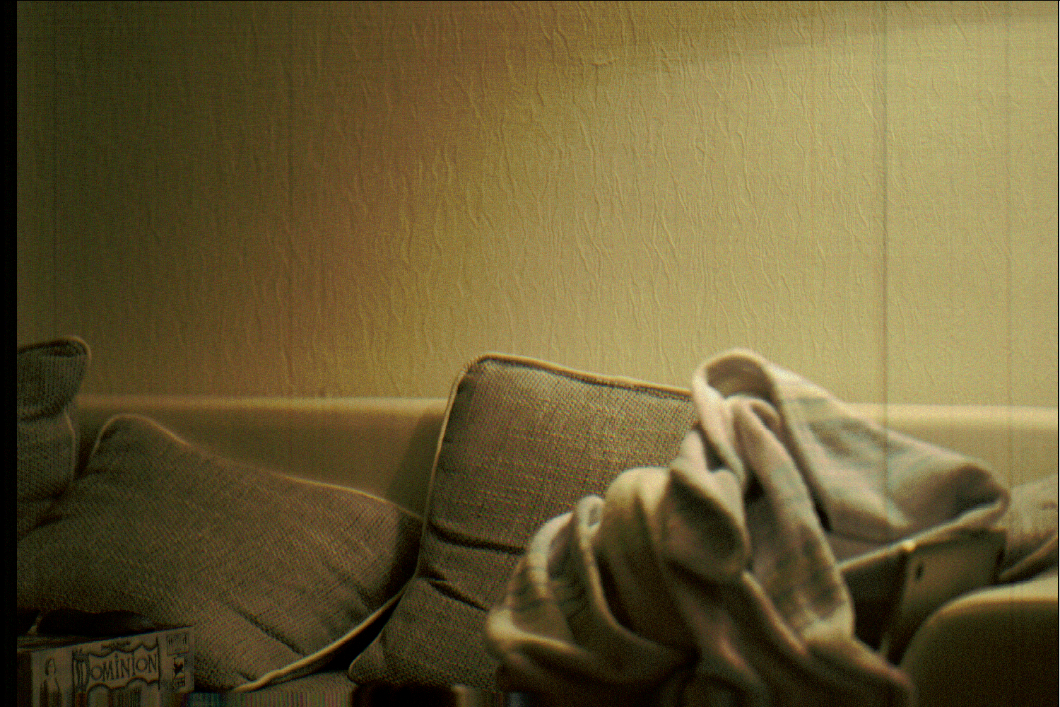
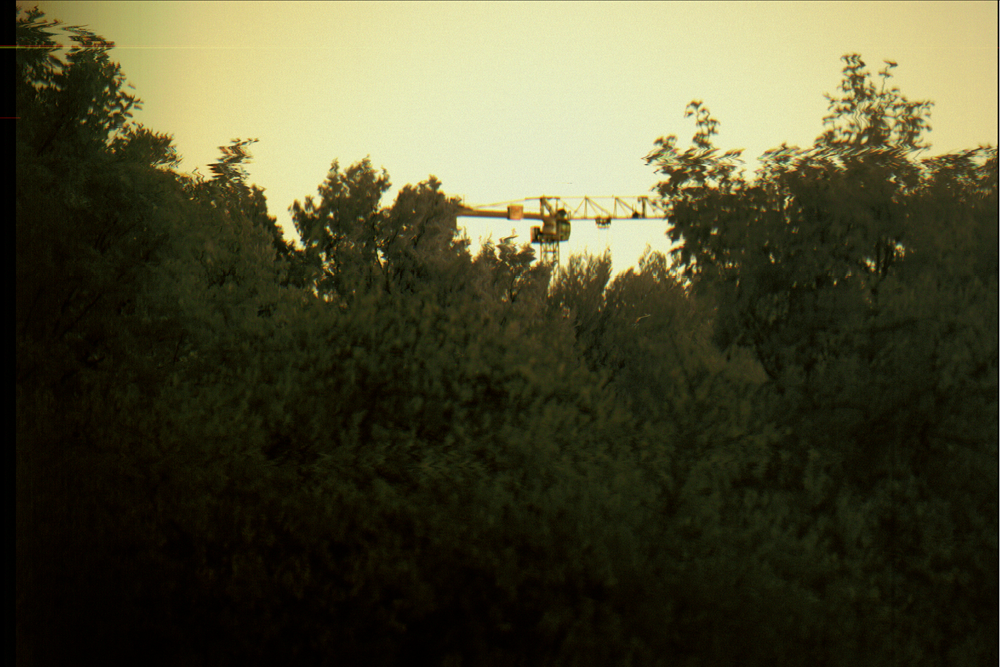
This is the first color scan. It shows a couch and a White/Gray/Red blanket without any post processing except adjusting dark/light values. The results had basically no color vibrance and incorrect white balance. I think this was a bad Idea, since the sensor doesn't have an IR filter and the room was lit with a halogen lamp.
Scans at sunset provided similar results, but were still very 'flat' and show little depth in color. Also the trees were moving, which is not very good for a scanning camera.
I tried to use lightroom to get the image as close to 'normal' as possible. It was very difficult since the green trees and blue sky have much too similar color. The small orange square on the crane is actually an illuminated red sign and it was a very nice sunset with a colorful sky.
The results from the test with my phone as light source were very good, but real world scans are incredible bad, which is discouraging. I will probably make some tests with better controlled lighting to see if the missing IR filter is actually a problem or the bad color response has a different cause.
So after a while I finally had the time and energy to continue with the project. I mounted the scanner to the camera and made first test scans!
After getting the hardware ready I tried to get the first scanned results. My initial tests showed, that the sensor was responsive to light, so I finished coding the scanning movement and logistics of scanning an image.
The first results were very discouraging. For hours I could only get noise without any hint of an actual image. The base-level however was responsive to light.
I tried to block half of the sensor and expose only a part of it. After a lot of searching I finally found a missing ground connection, and after fixing it things got better.
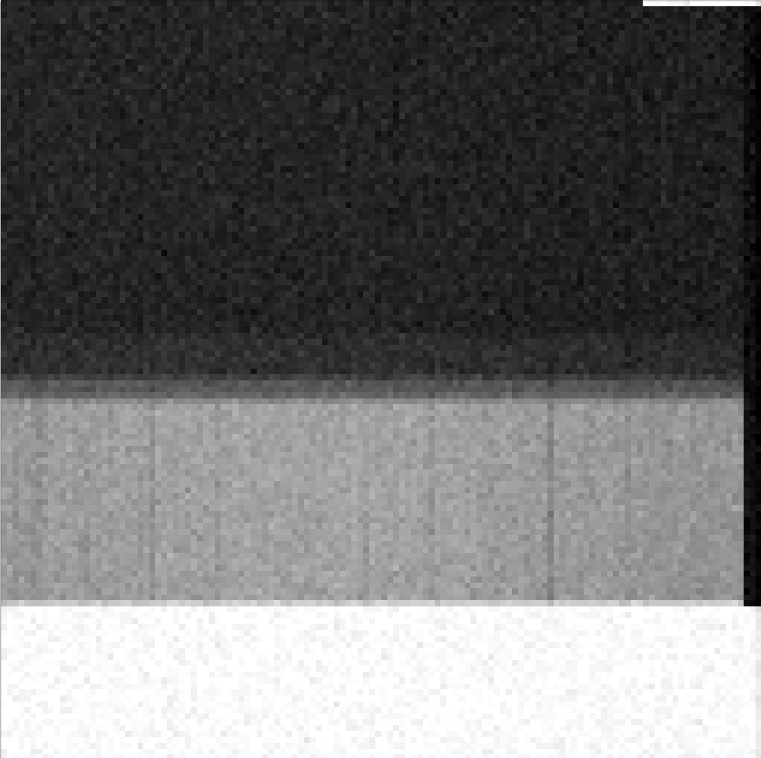
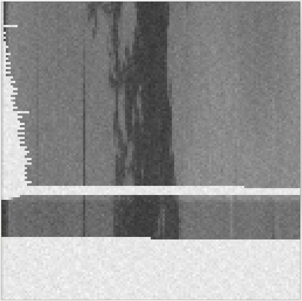
A test sketch printed every 100th pixel in the line, and if you look closely you can see the initial dark pixel at the top (65535), then some lighter pixels (~55k), then dark pixels again. Finally the sensor was working as intended. Getting a scan however was still not working. Only pure randomness, without any image. After a lot of time trying to find the error I finally had it!
The very first image. After 20 images of pure randomness, finally something appeared! Clearly distinguishable from random! Not much, just a hint of a pine tree! The issue was found, and it was actually just a missing delay for the integration time of the sensor.
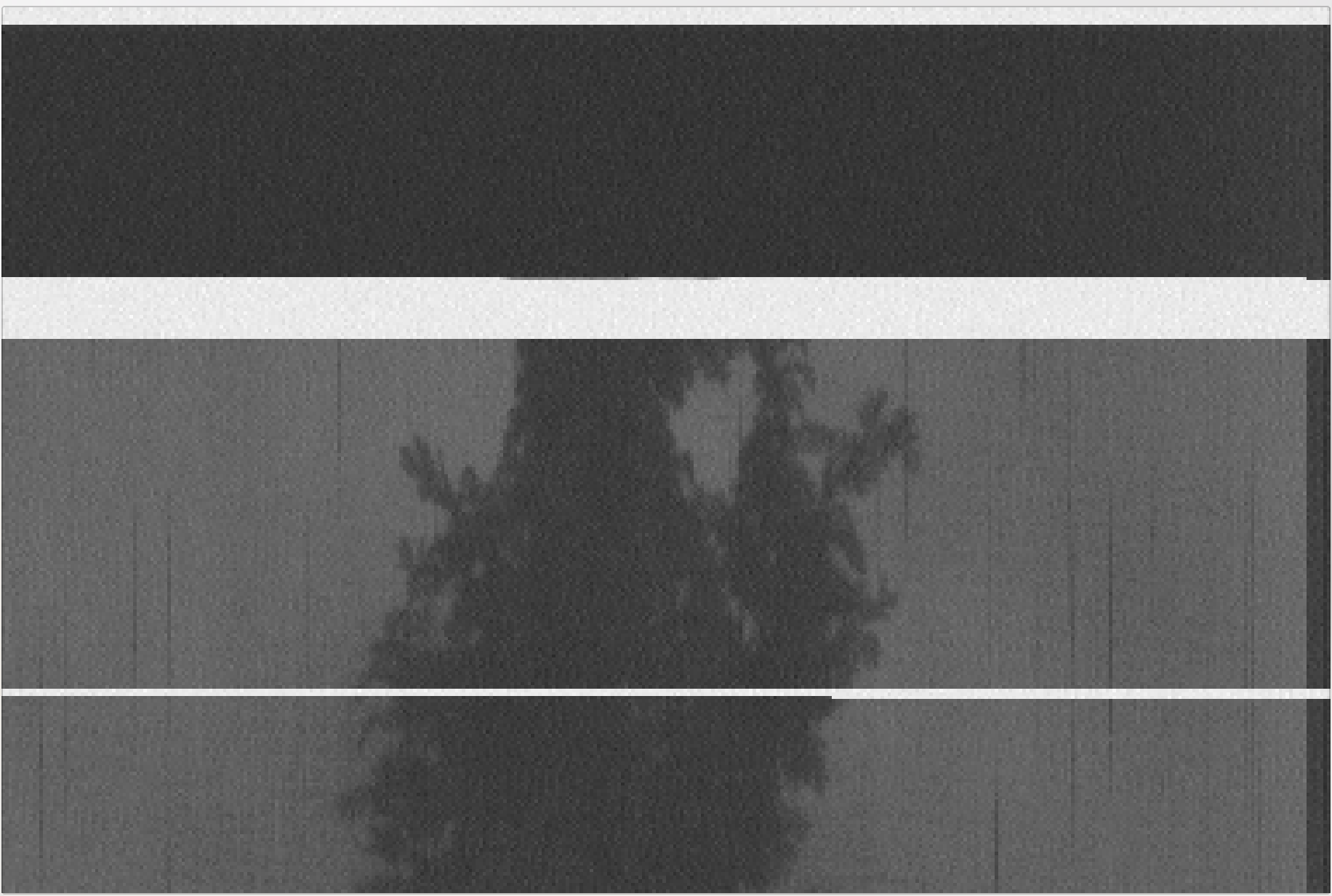
Time for some fun! Basics were working, so I fixed a lot of things like aspect ratio and flipped the image in post processing. This is the second ever image from the scanner (with distinguishable features). At the top I forgot to take the cap from the lens (dark part), then I adjusted the aperture (light part).
The white pixels are caused by pixels 'overflowing' with too much exposure. Sometime this gets so extreme that a few lines are completely white. The white area in the middle of the picture was caused by the sd-card write blocking the scanner for a few seconds.
The integration time for a linear ccd is the time it takes to read the previous line. So before each actually sampled line there is a dummy read out to 'flush' any exposed pixels out of the sensor. This gives a well defined integration time between dummy read-out and actually sampled read-out.
The blocking sd-card however is still a problem, because it is so long, that one dummy read-out is not enough to flush out the extremely over exposed pixels. It takes a few more lines for the sensor to get back to normal.
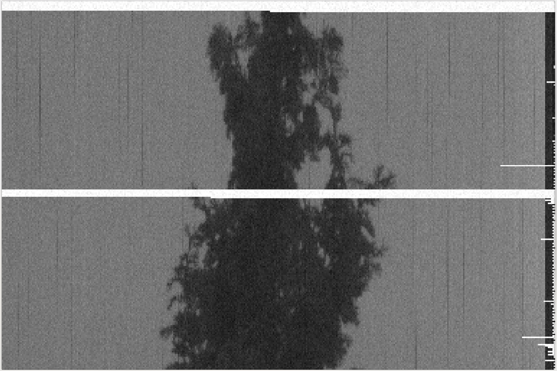
This is one final glamour shot at 2000x3000 pixels.
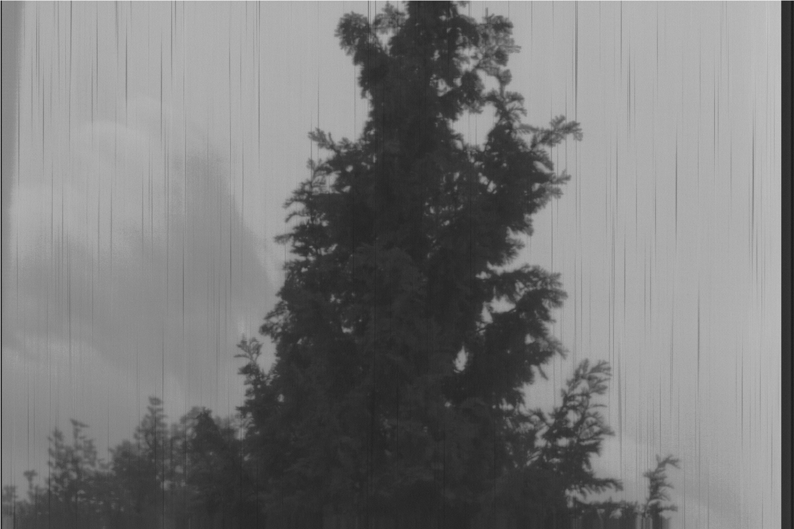
After more fixes with additional dummy read-outs the white pixels disappeared, and the image started to look a lot cleaner. The focus is a bit off, but it still looks amazing for the first results. The black streams are most likely caused by the mosquito net in the window.
This is by the way only one color channel of the rgb sensor. The image format is just a plain binary concatenation of pixels. It needs post-processing...
Read more »The wiring is complete, and instead of making the first experiments with the old arduino due I decided to use the teensy 3.6 directly.
I have ported the code from the due sensor reading sketch and made a new one for the teensy 3.6. There was only a quick test if I get values from the sensor, but it looks good. Iterating through one line without using the ADC takes about 5ms, which is not so bad when you consider, that it's still using arduinos standard digitalWrite to bit-bang the signals for the sensor, and one line takes about 3200 clock cycles. When using the ADC to read one of the six output lines it takes about 26ms for one line.
Stepper movement and sd card writes are also working, so I really just have to put everything together and I should be able to get the first scans!
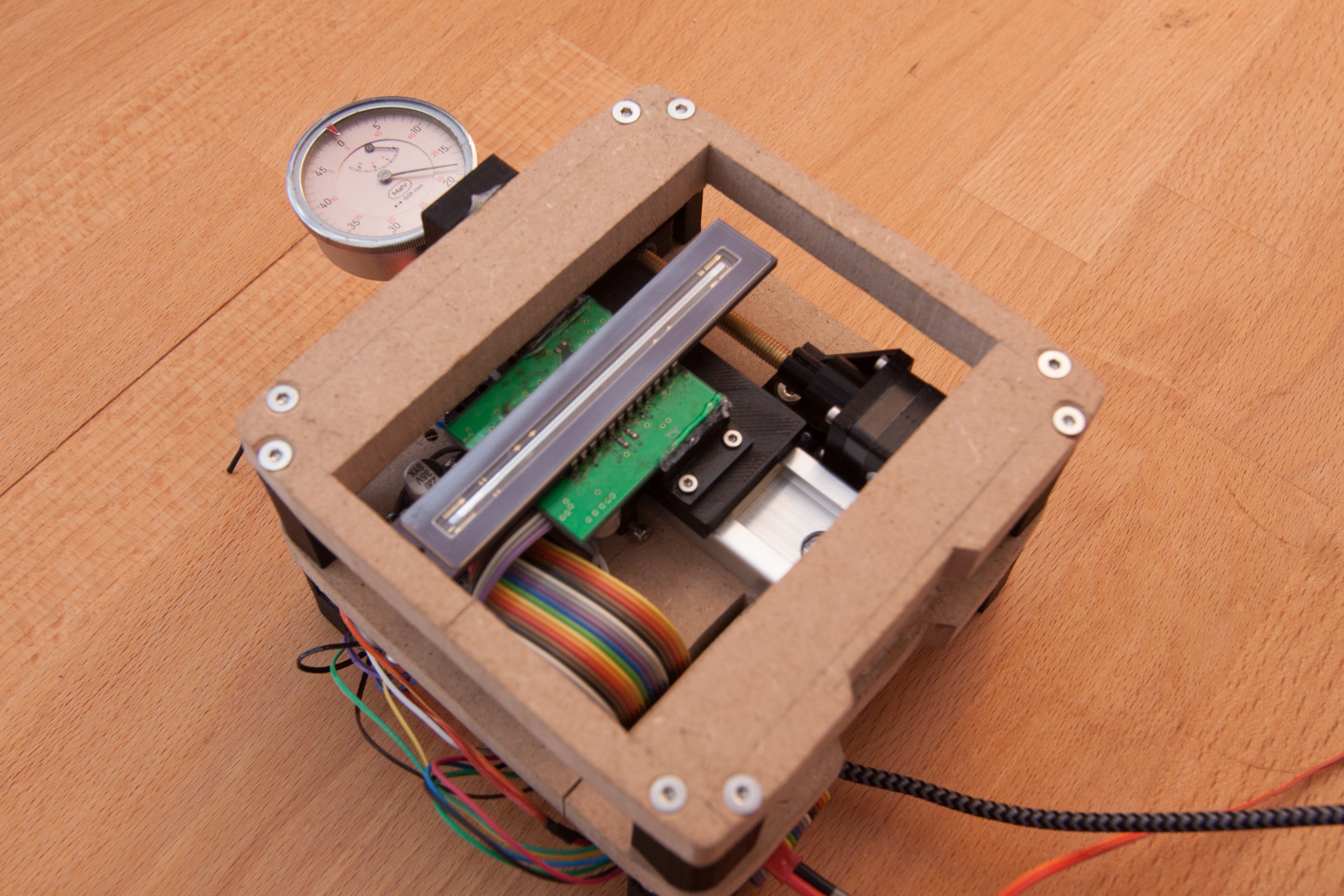
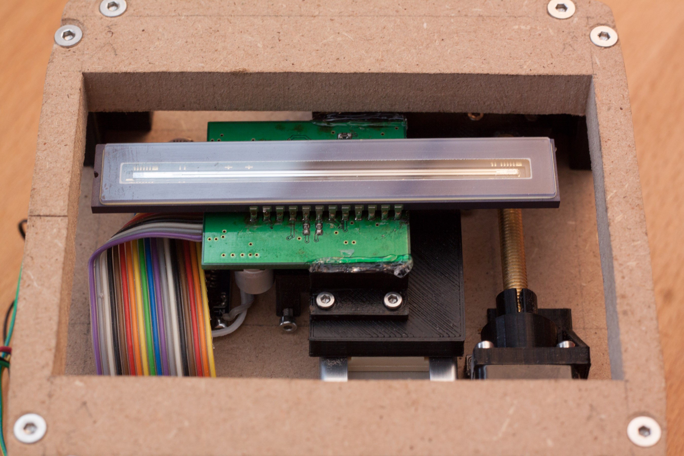
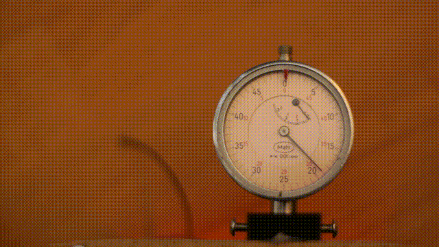
Mounted the sensor and finished wiring for first experiments. A dial indicator to verify, that the axis movement is precise enough can be seen at the top left.
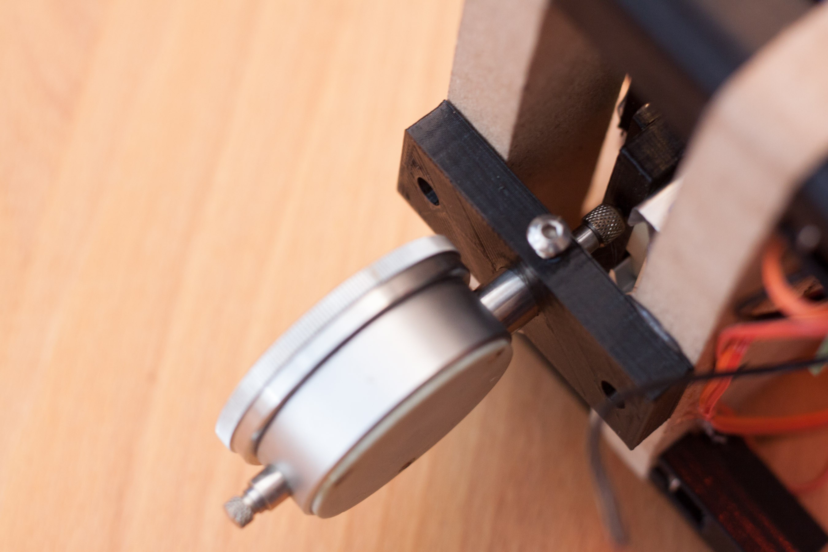
Detail shot of the dial indicators mounting, and where the carriage pushes against it.
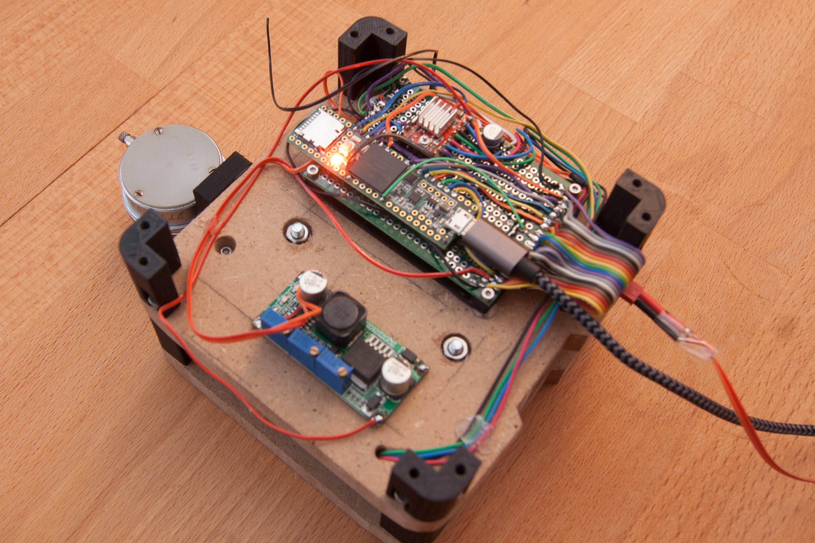
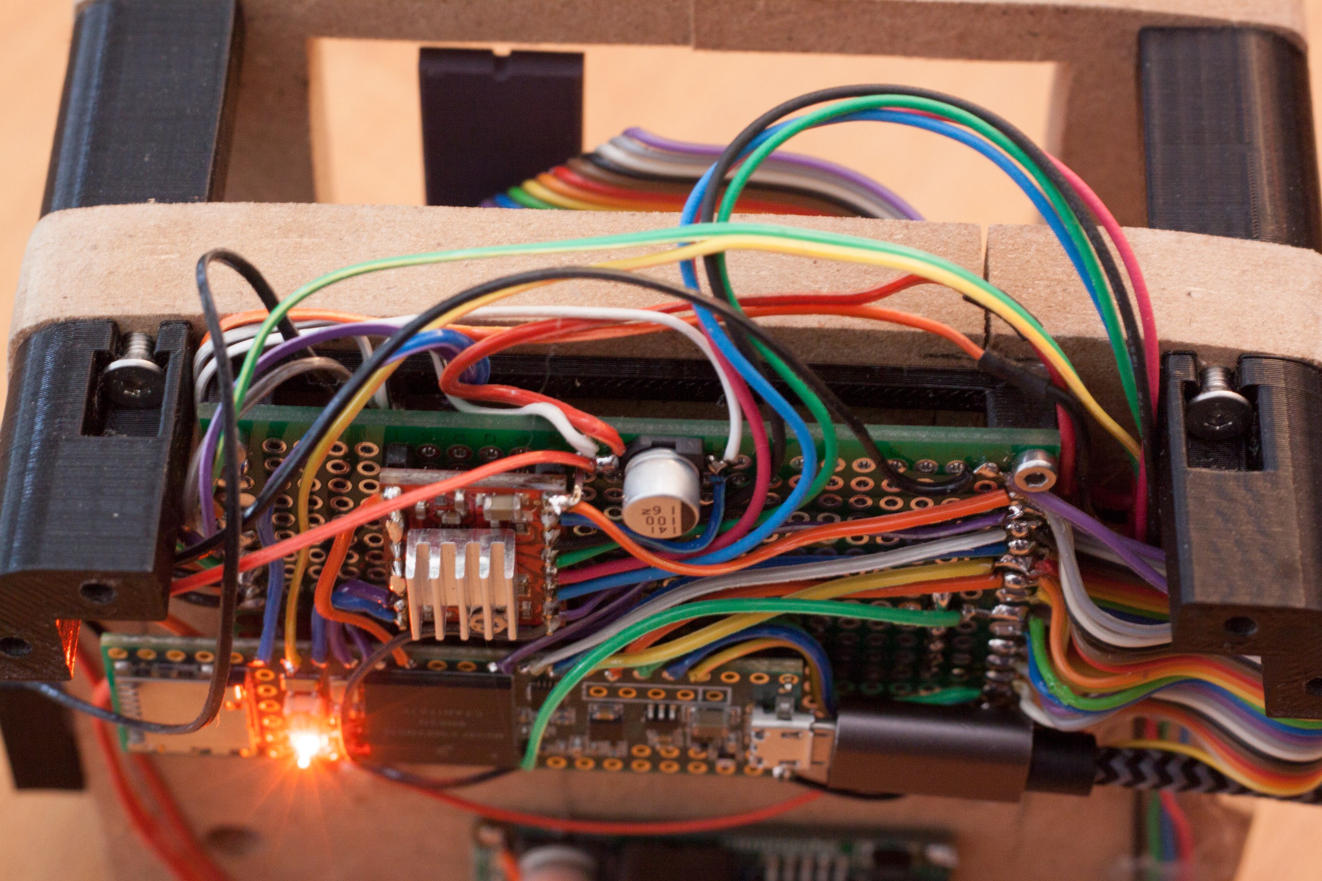
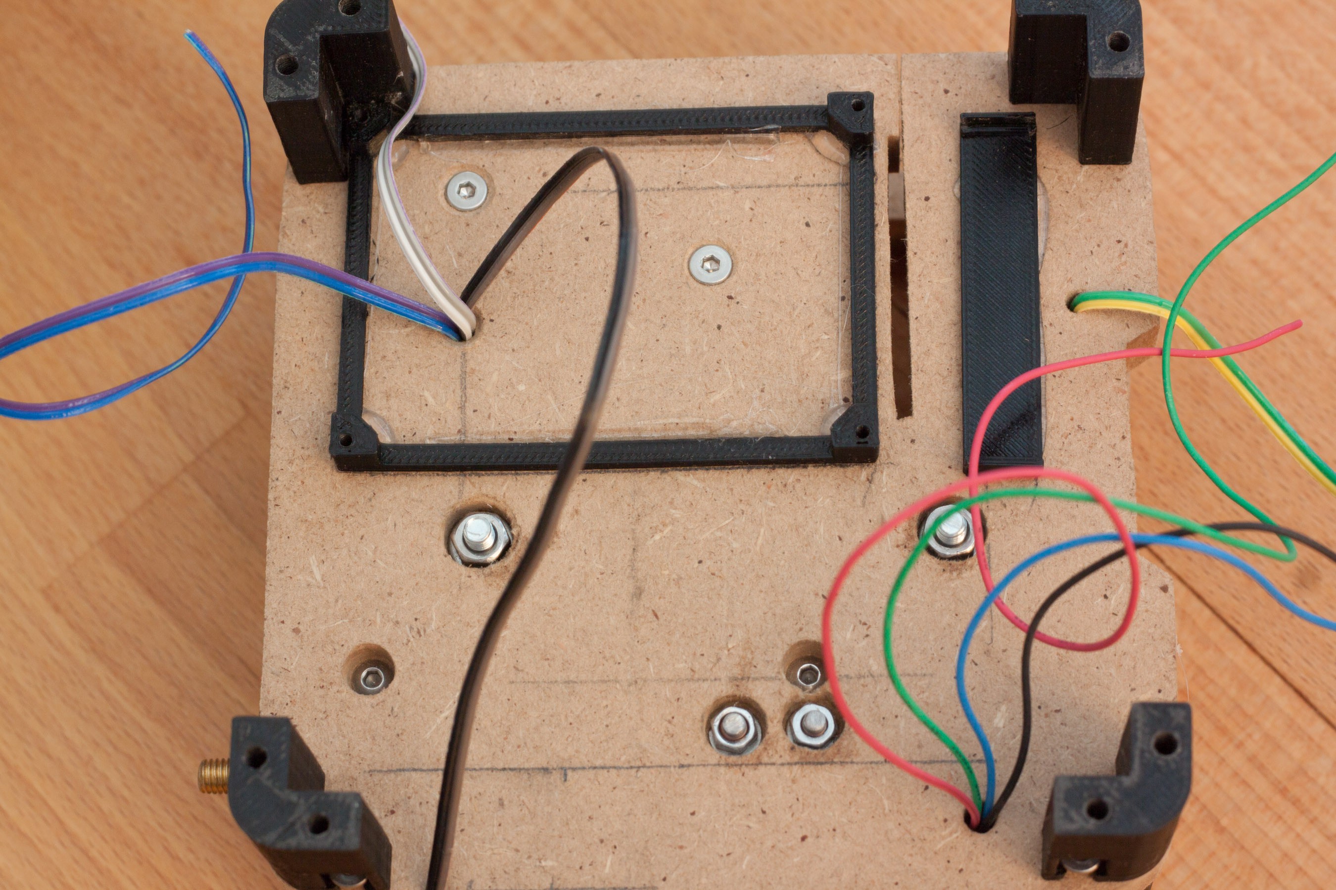
Wiring. It is not very pretty, but functional. The teensy and stepper driver have soldered to the perf board with only 4 pins each, this makes removing them later much, much easier. The connections are made on top of the pcb, because this way it is easy to make changes without removing the pcb. For prototyping this is very useful.
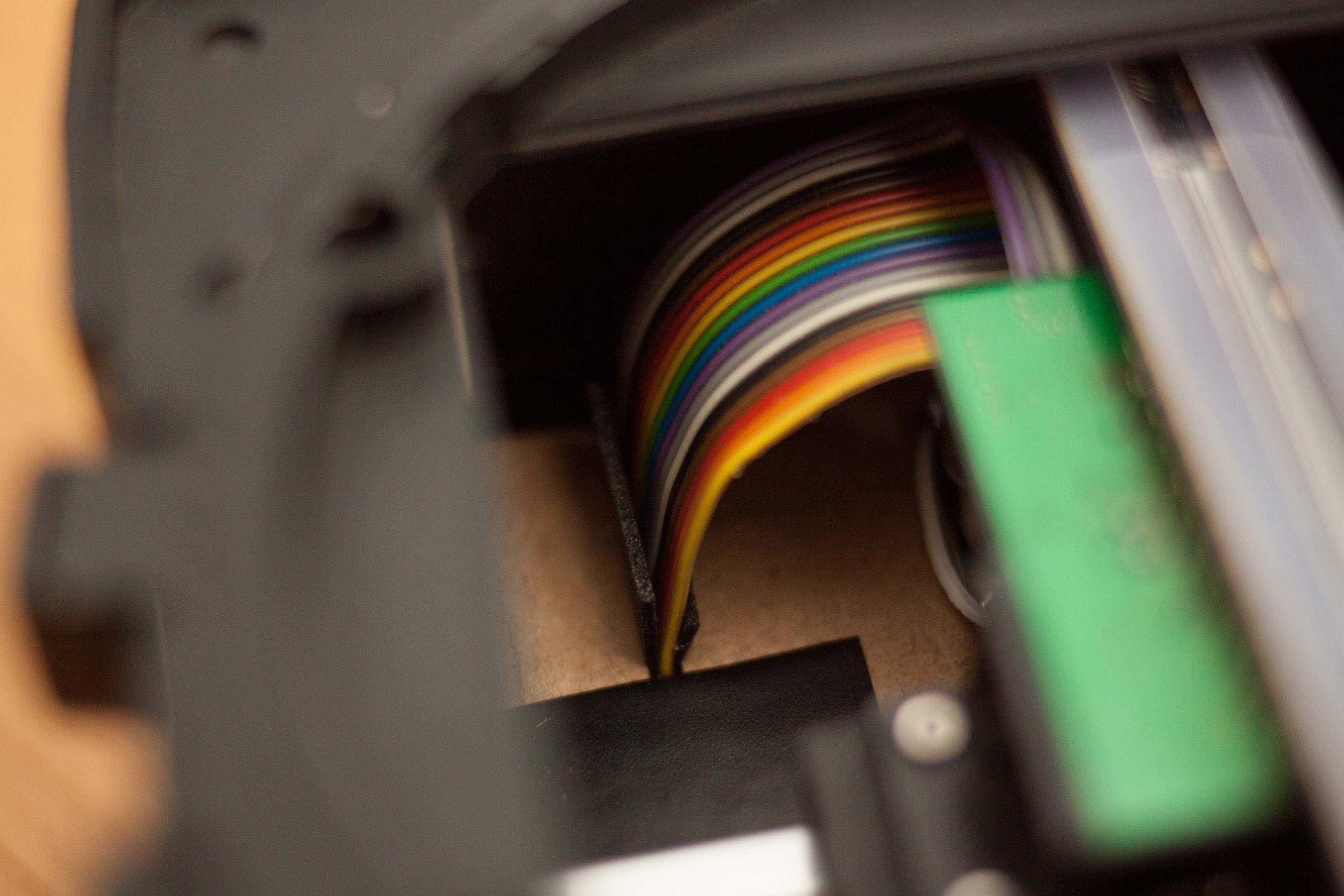
Detail shot of wiring. I tried to get the bent sensor cable into the picture. It starts at the sensor pcb (not shown) at the top, goes through the wooden mounting plate and is soldered to the right end of the perfboard.
Another picture of the sensor pcb and the sensors cable. Please excuse the hot-glue, I didn't have anything else on hand and it's better than a sensor dangling around.
With the mounted dial indicator I made a sketch that moves one step per second (until it hits the endstop). If you look closely, it seems like the dial moves about half a mark per step, which matches the desired 4µm per step. (One mark is 0.01mm or 10µm) Some steps seem to be a little larger or smaller, but in general it looks surprisingly good.
I also don't want to rule out measuring errors by the dial indicator, which doesn't feel very 'smooth' when pushed by hand.
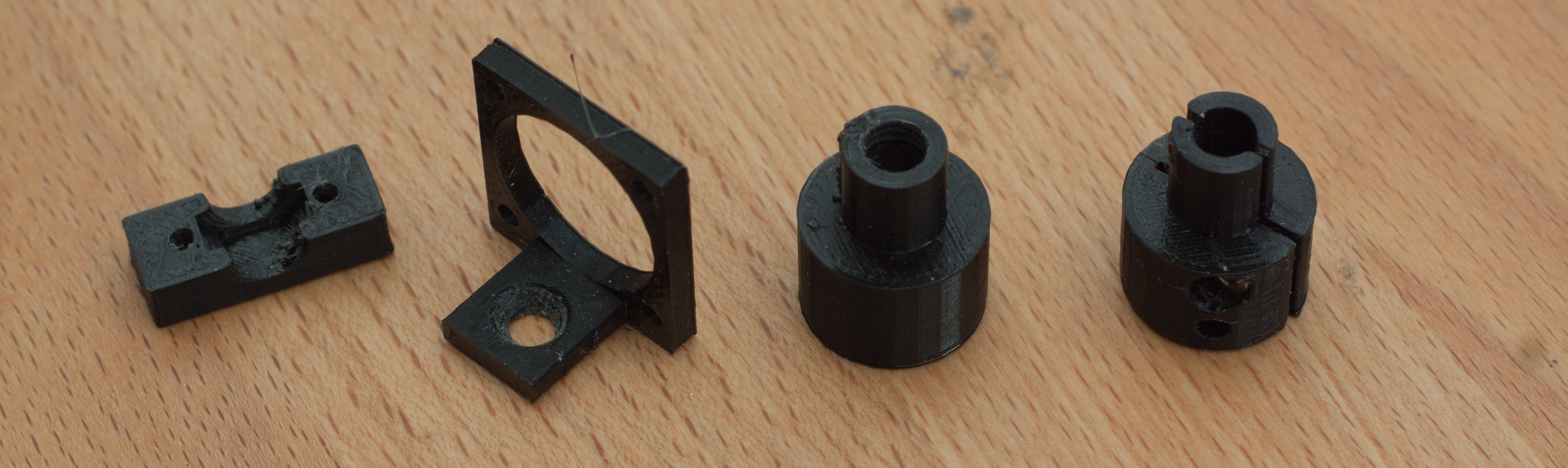
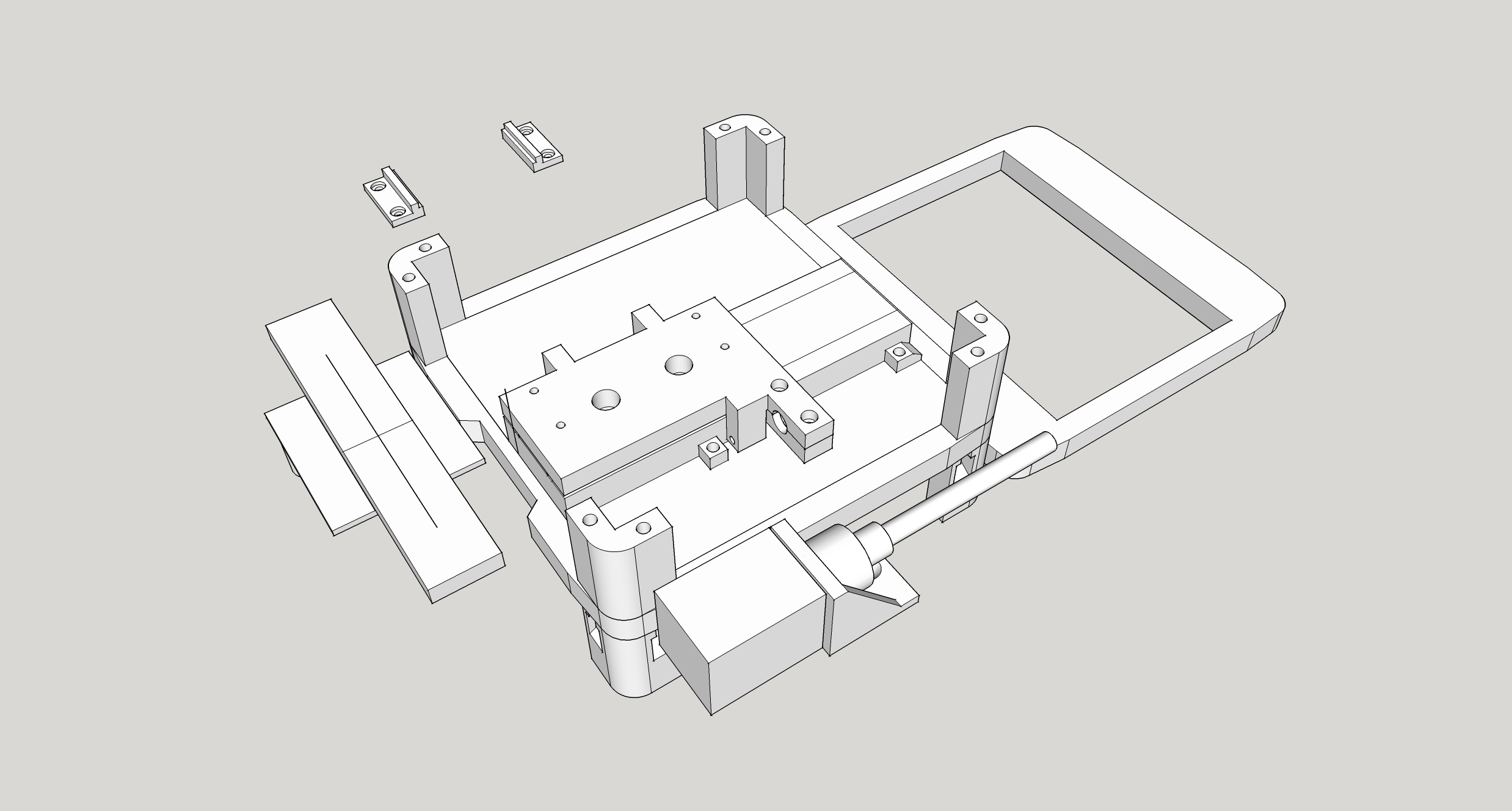
After finishing the design in Sketchup I started printing everything. The largest part is the carriage that gets mounted on the linear guide rail. An important area with critical dimensions is the mounting for the lead screw nut (actually just a regular steel M5 nut). These areas usually go through one or two iterations until everyting fits perfectly, so I made a test-print of just this area before acually printing the large part. This is much faster, as the complete carriage part takes about 1.5h to print.
Most other parts were rather simple and didn't require any iterations. The first version mounting bracket for the stepper motor was way too soft and unstable, so this and the lead screw coupling were the only parts that had to be changed. If you compare the stepper mounting bracket in the first picture versus the later pictures you can see the added triangle for stiffening, added thickness, and that it gets fastened with two screws instead of just one.
(First-) iterations of various parts.
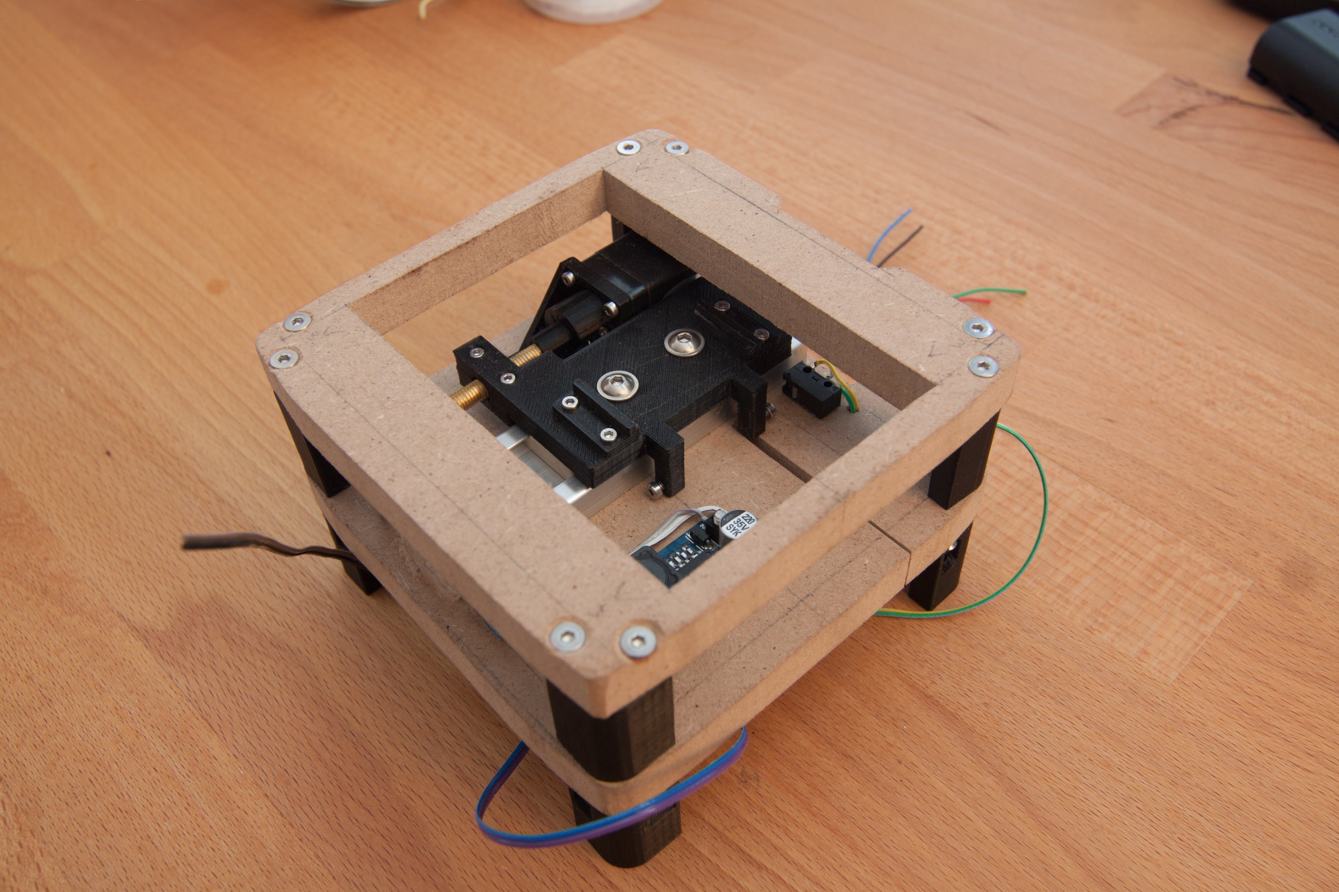
Overview shot of the whole assembly.
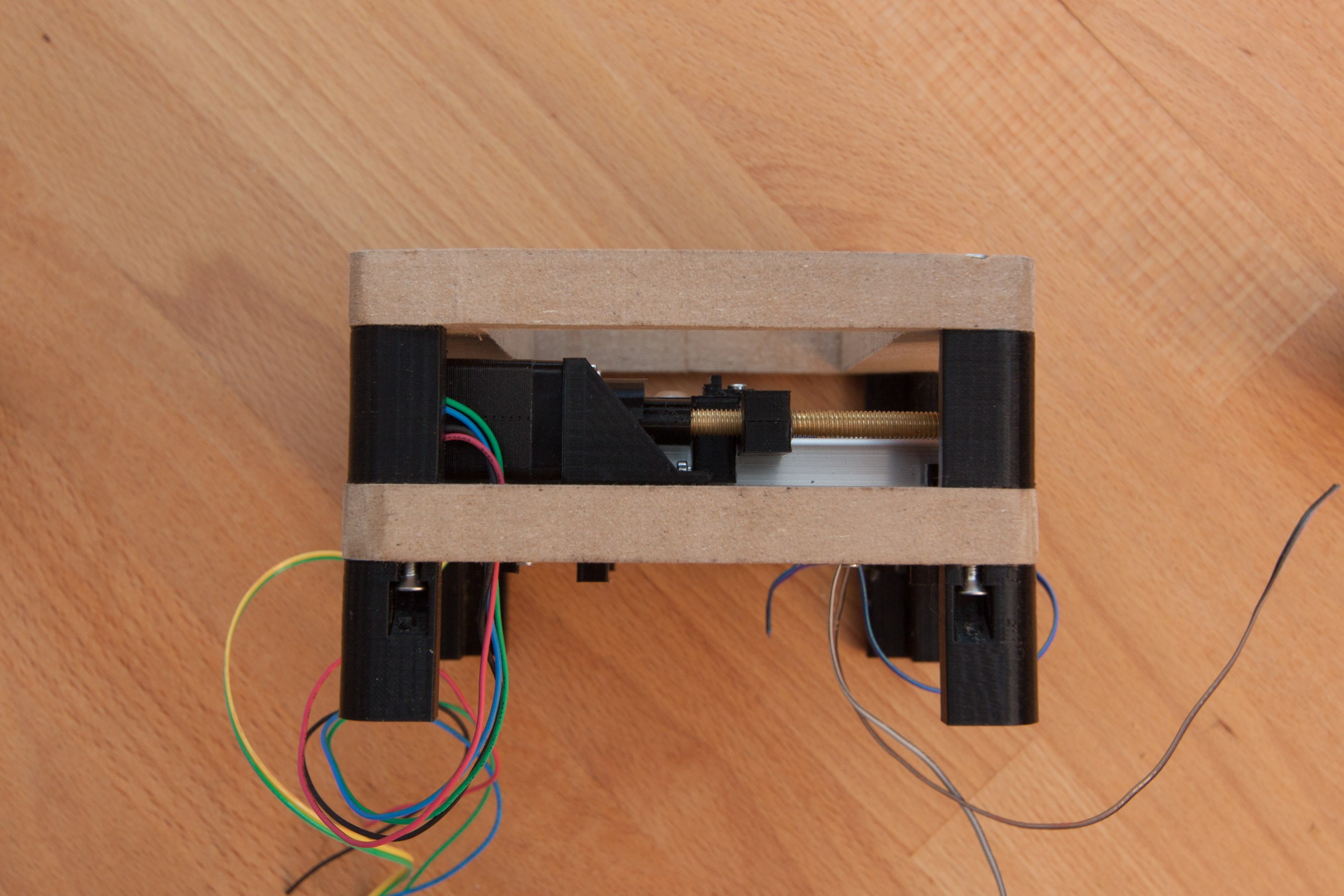
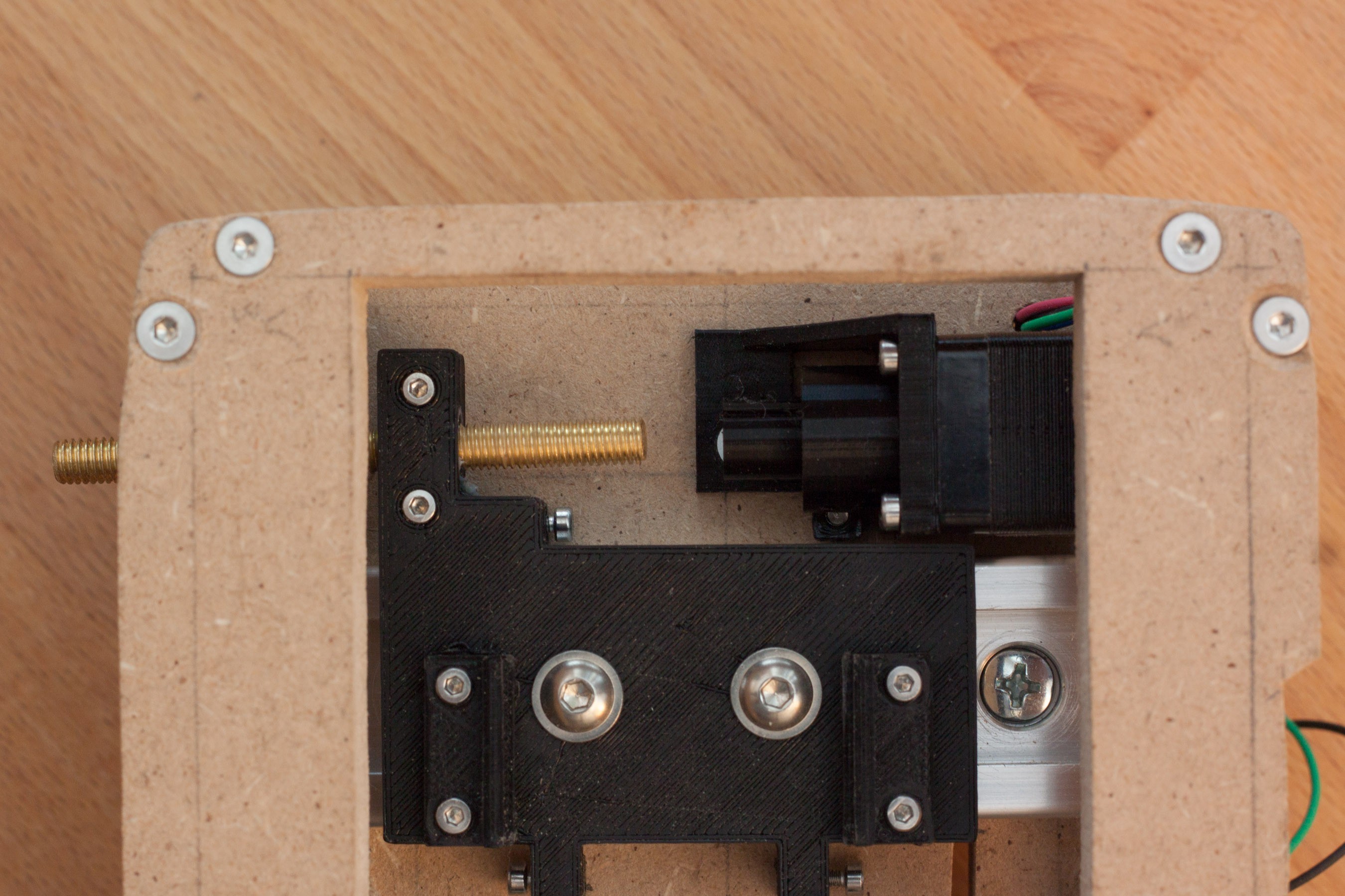
This picture shows the stepper mounting bracket, lead screw assembly, and how the spacers between the mdf plates are fastened.
Also lead screw, stepper motor bracket, and carriage with the two adjusting screws for the endstop switches at the bottom. One half of the mechanical endstops is also visible just below the lead screw and below the coupling.
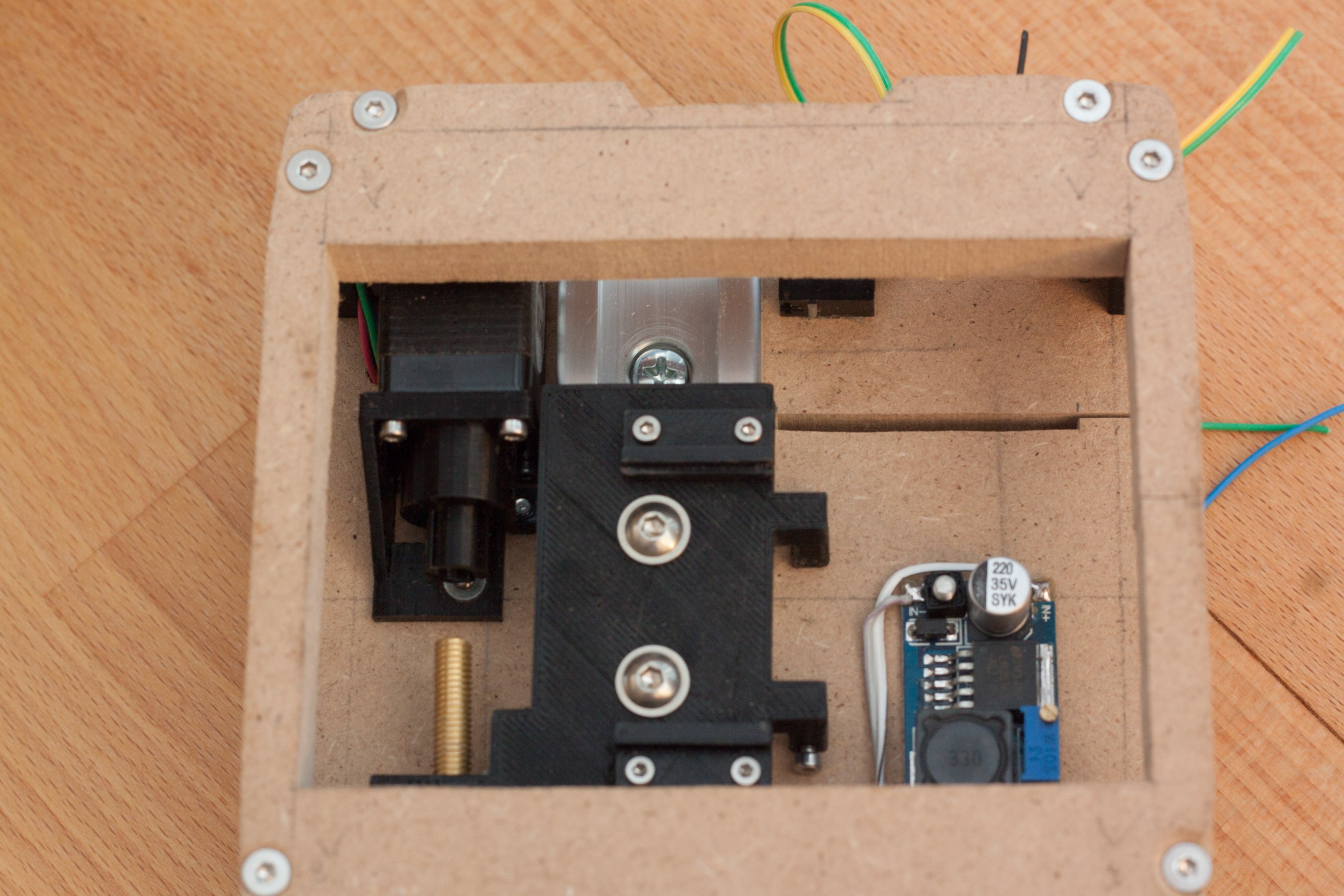
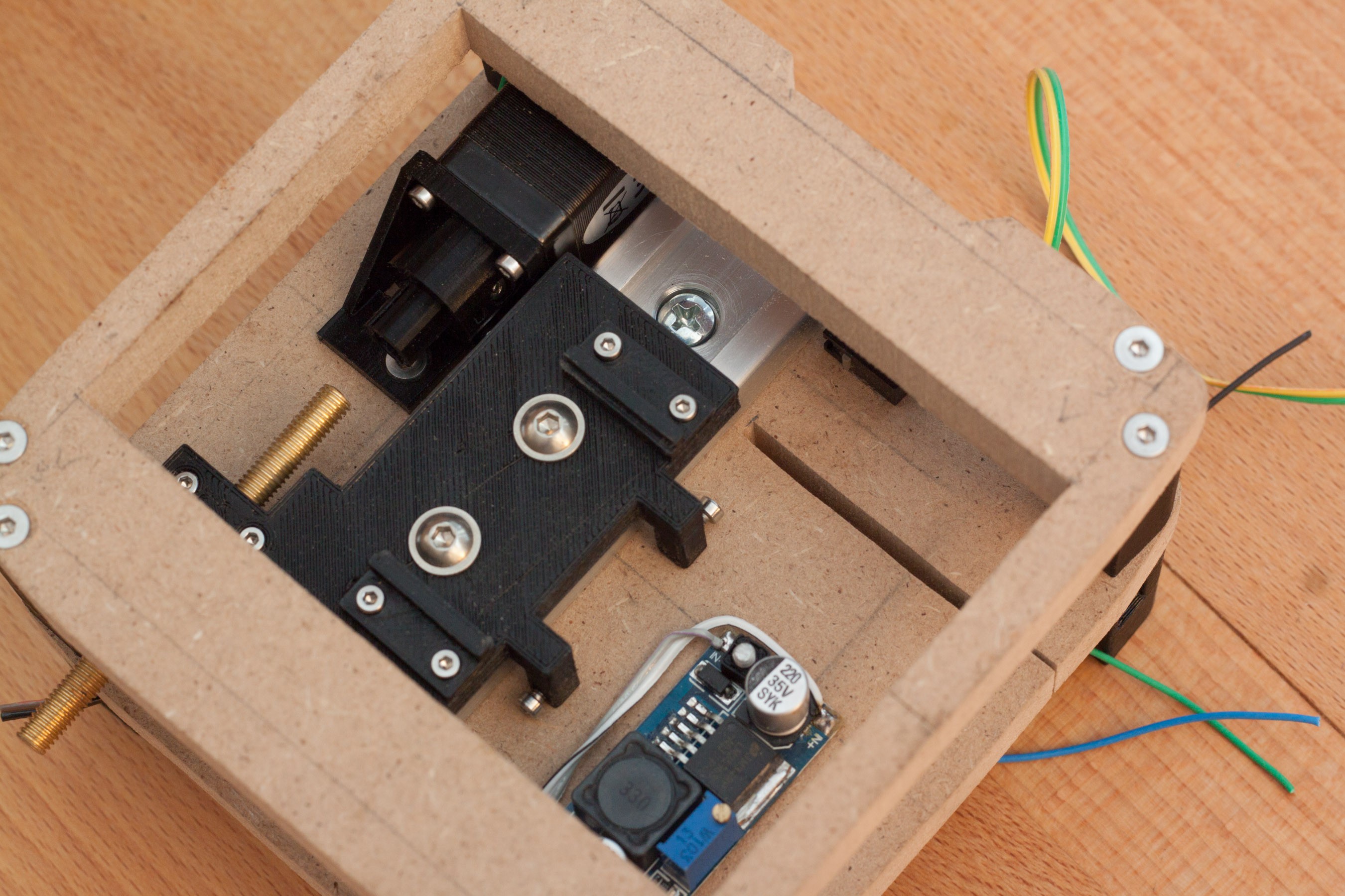
A step-down dc-dc converter was mounted in this area, because there was unused space.
Detail shot of the adjustable endstop switch. The two small pieces on top of the carriage are the mounting for the sensor pcb. They are separate pieces from the carriage, so the carriage is easier to print, which helps to get the critical dimensions right. Another reason is, that the mounting can be changes easily with new designs.
Back Side with cables for endstops, step-down converter, and stepper motor. Counterbores for the screws and nuts are also shown. This is done, so the surface of the mdf plate is plane and it is easy to mount other components on it.
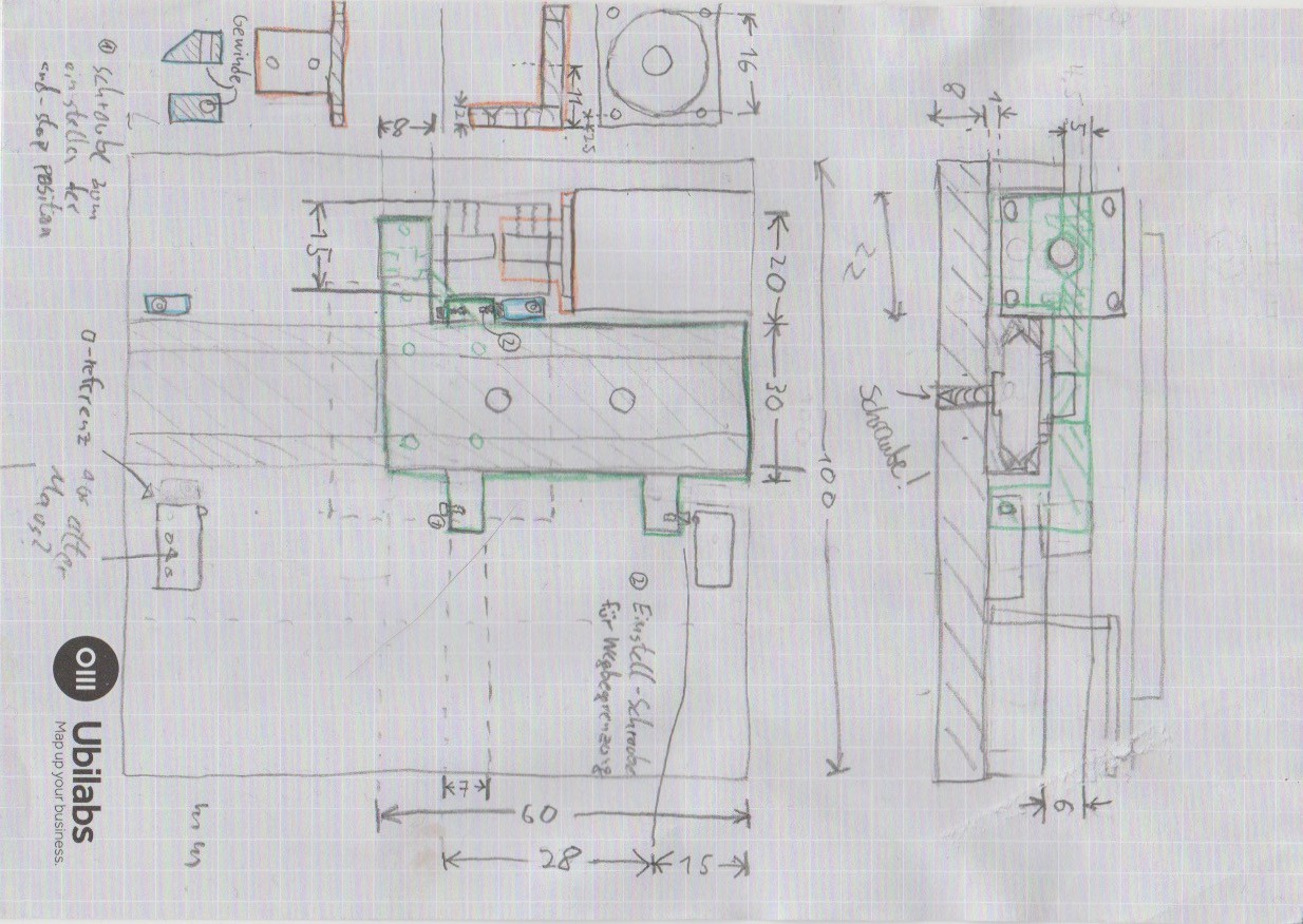
Design of the basic hardware
I started designing the hardware around the linear guide rail. Requirements were simple: 40mm movement and, height of the whole assembly as low as possible.
So I started sketching on my notepad and searched ebay for a suitable stepper motor. I found a nema 8 stepper, that was short enough to allow a directly mounted lead screw and 200 steps per revolution, which together with a M5 screw results in exactly 4μm movement per step. I don't think this assembly can achieve this precision, but this means, that the 8μm per scan-line are exactly two steps, which is very good. Note that these are full steps, not micro steps. Microstepping will not really help to improve positional accuracy. There was a hackaday article about that some time ago, but I don't want to look it up now.
This is how these sketchs usually look like. There are a lot of rapid changes while each part gets refined, and refined again after thinking about how it moves, and how it fits together. So it looks a bit rough at the end, and the apple cider I just poured over it while writing this log didn't help...
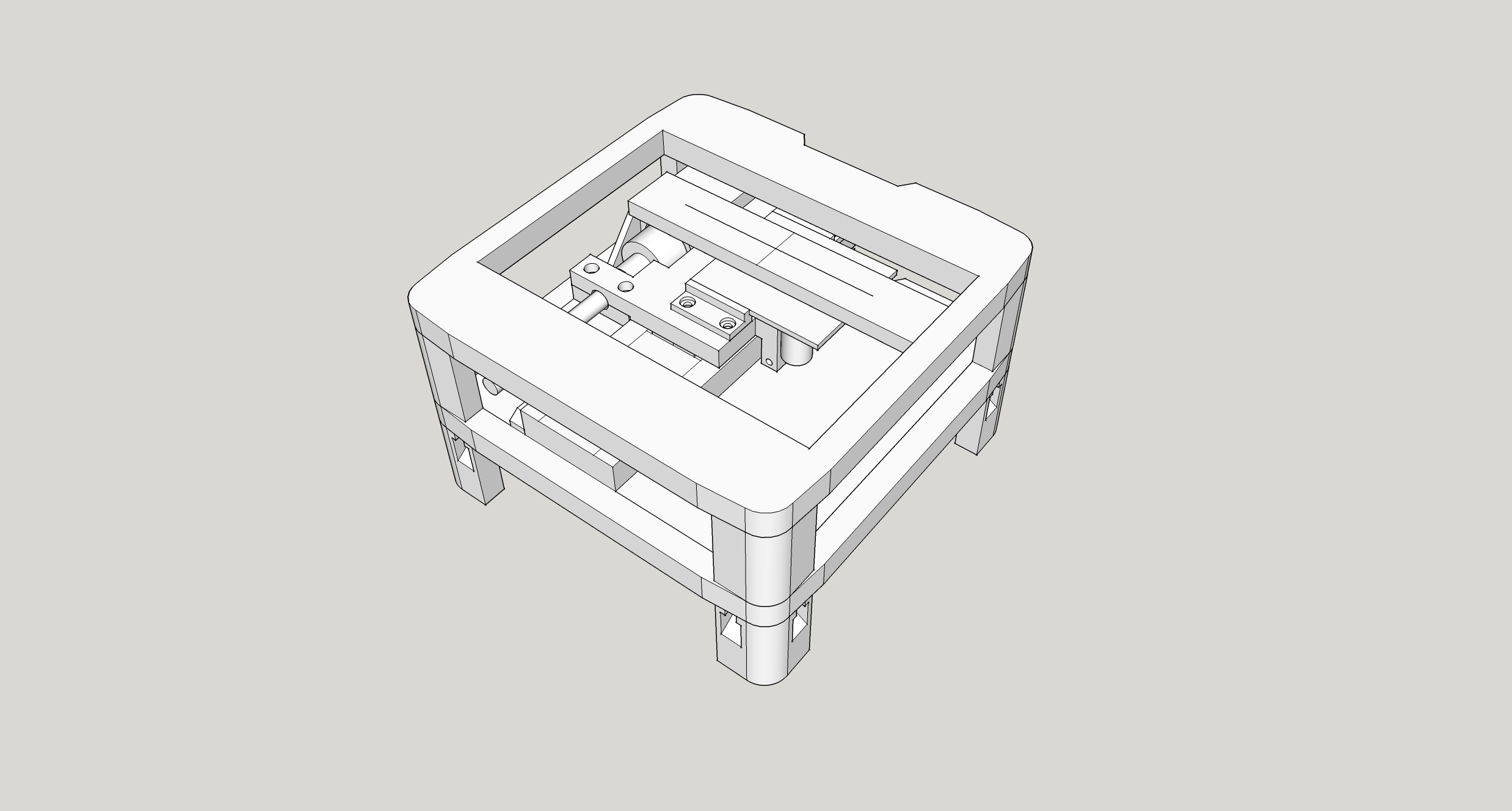
Finished design
After enough hand drawn iterations a 3d model of the whole assembly was made. This is not only useful because most parts will be 3d printed, but the 3d visualisation also makes it easier to find any problems of moving components not having enough clearance, not reachable screws, etc.
The first image shows the side where it gets mounted to the camera. The long part inside the window with the cross on top is the sensor. At the top corner. The two flat plates will be made out of mdf and everything else will be 3d printed. The linear axis has adjustable mechanical endstops, and adjustable endstop switches on both ends.
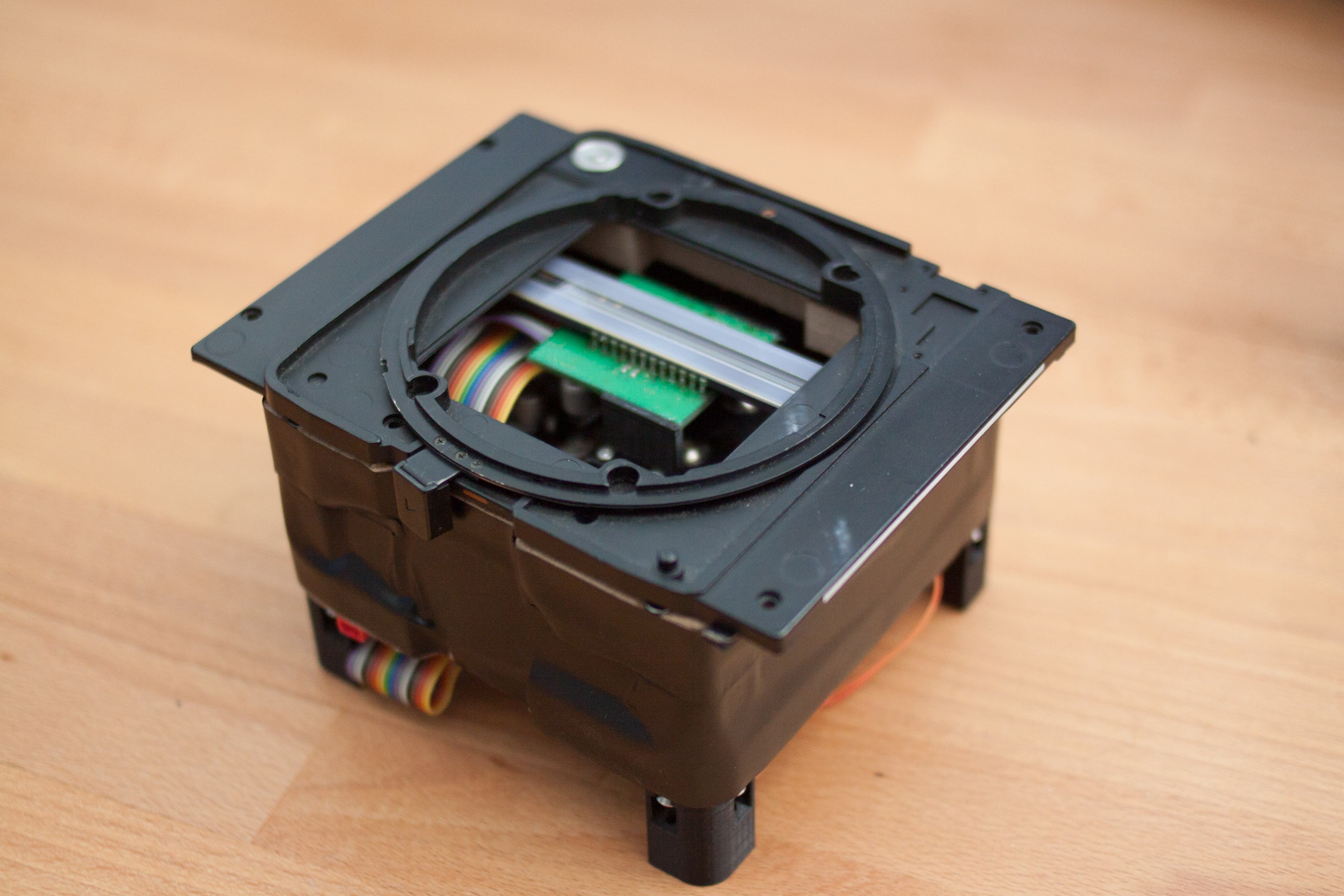
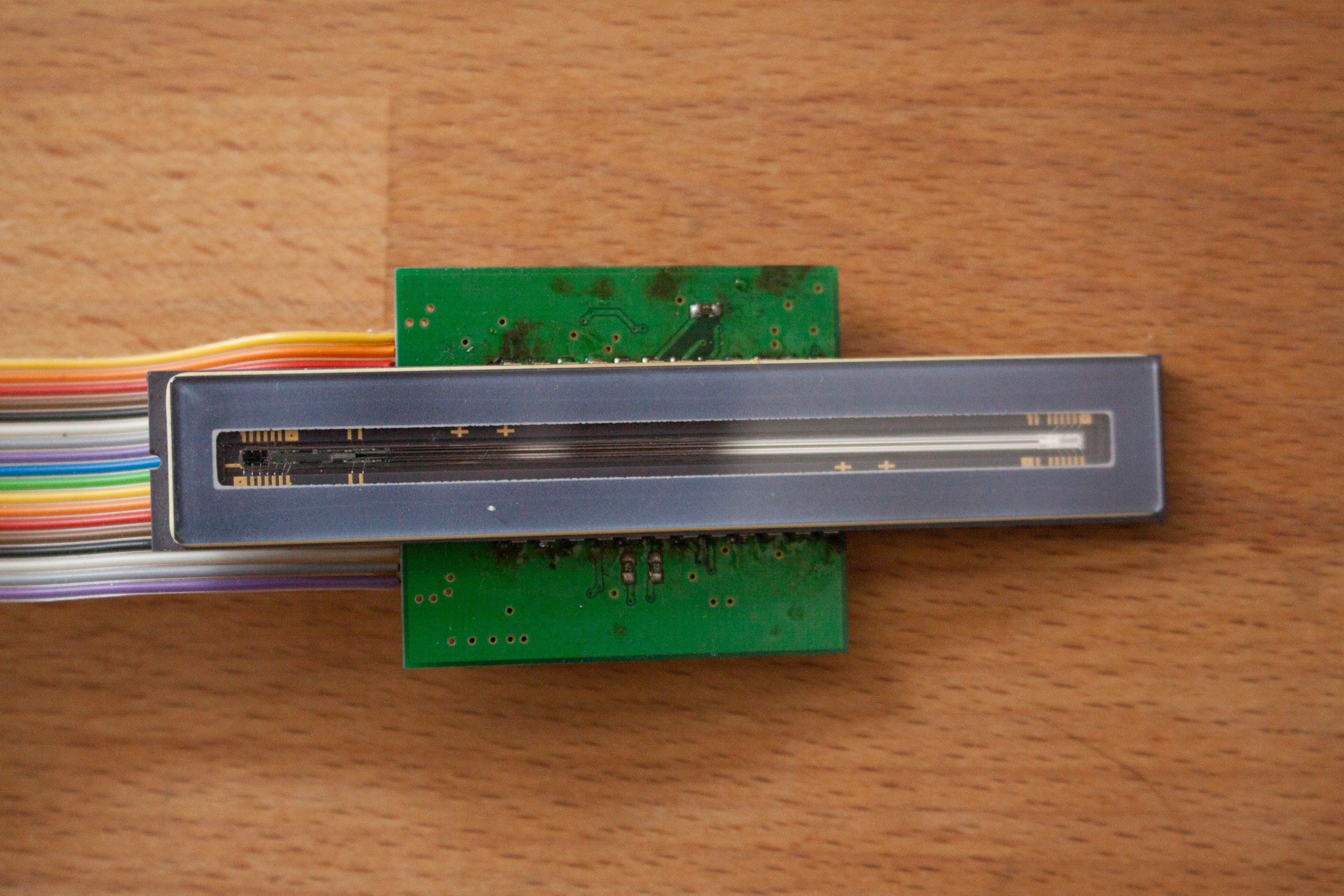
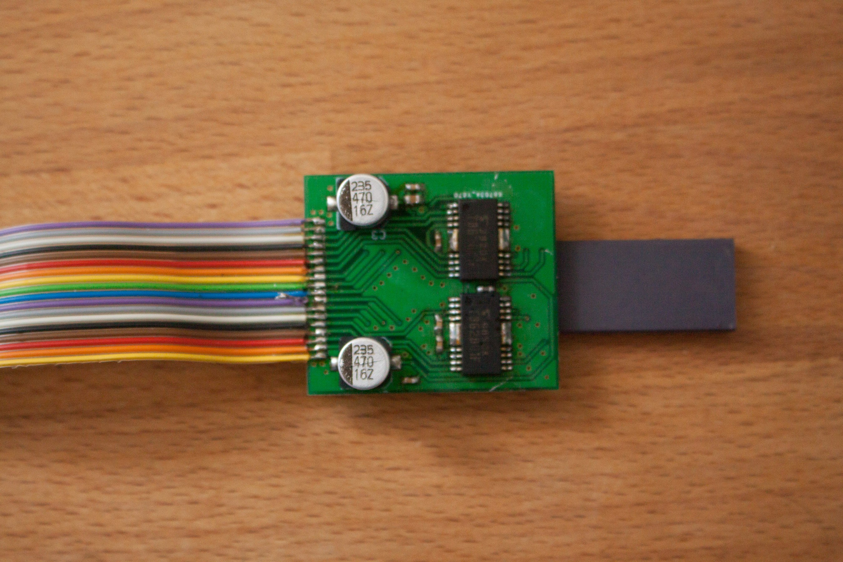
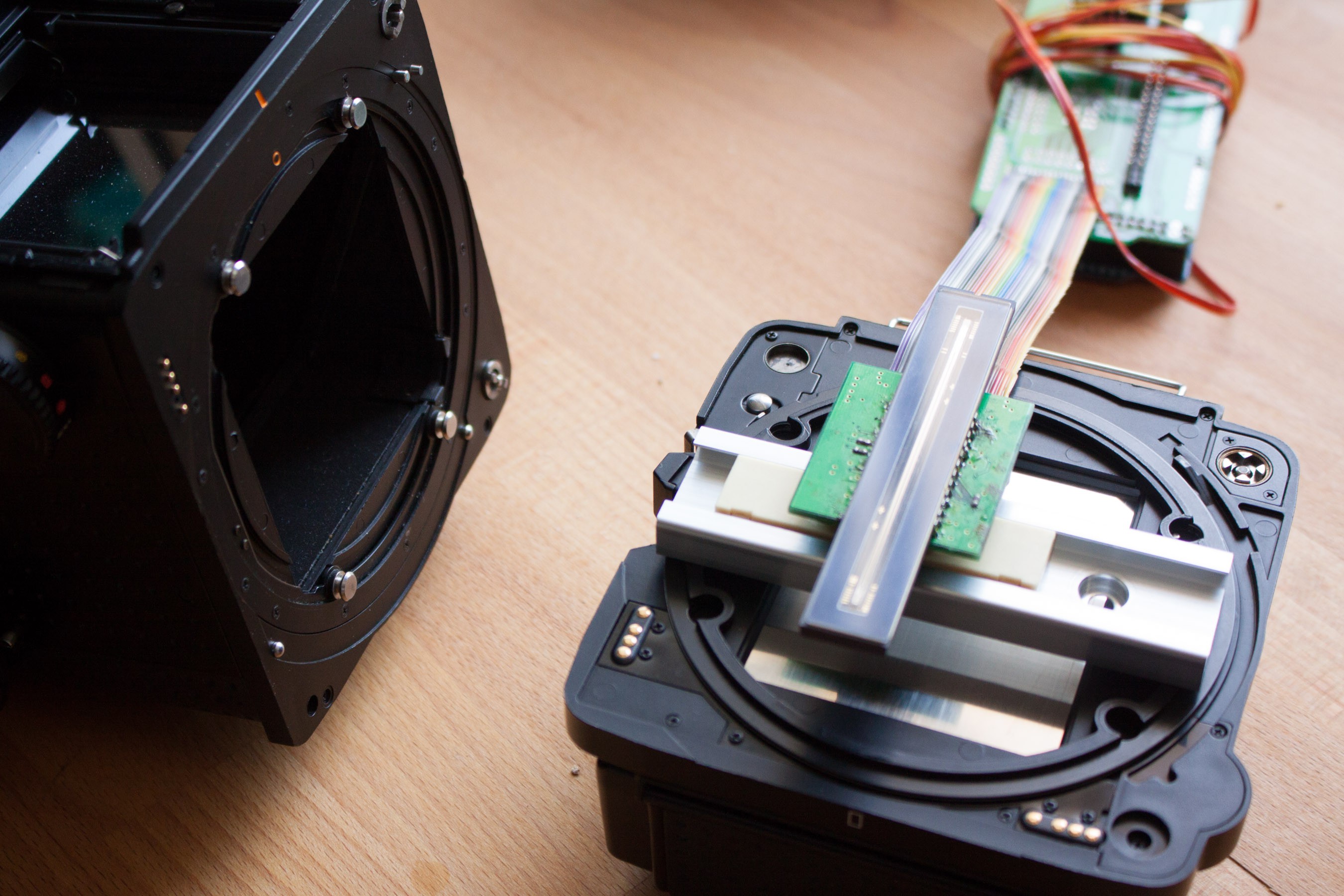
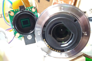
Sensor with driver-board and arduino
This is the toshiba tcd2700c linear ccd. I made a board with the drivers. Interfacing the sensor with the arduino was rather tricky, as it requires a differential clock and draws quite some current. The first versions didn't use the original toshiba drivers and simply didn't work.
The PCB on the arduino already has a stepper driver on it, because I wanted to use it for a non-portable scanner, so the arduinos size was no problem. In this project I want to replace it with a Teensie 3.6.
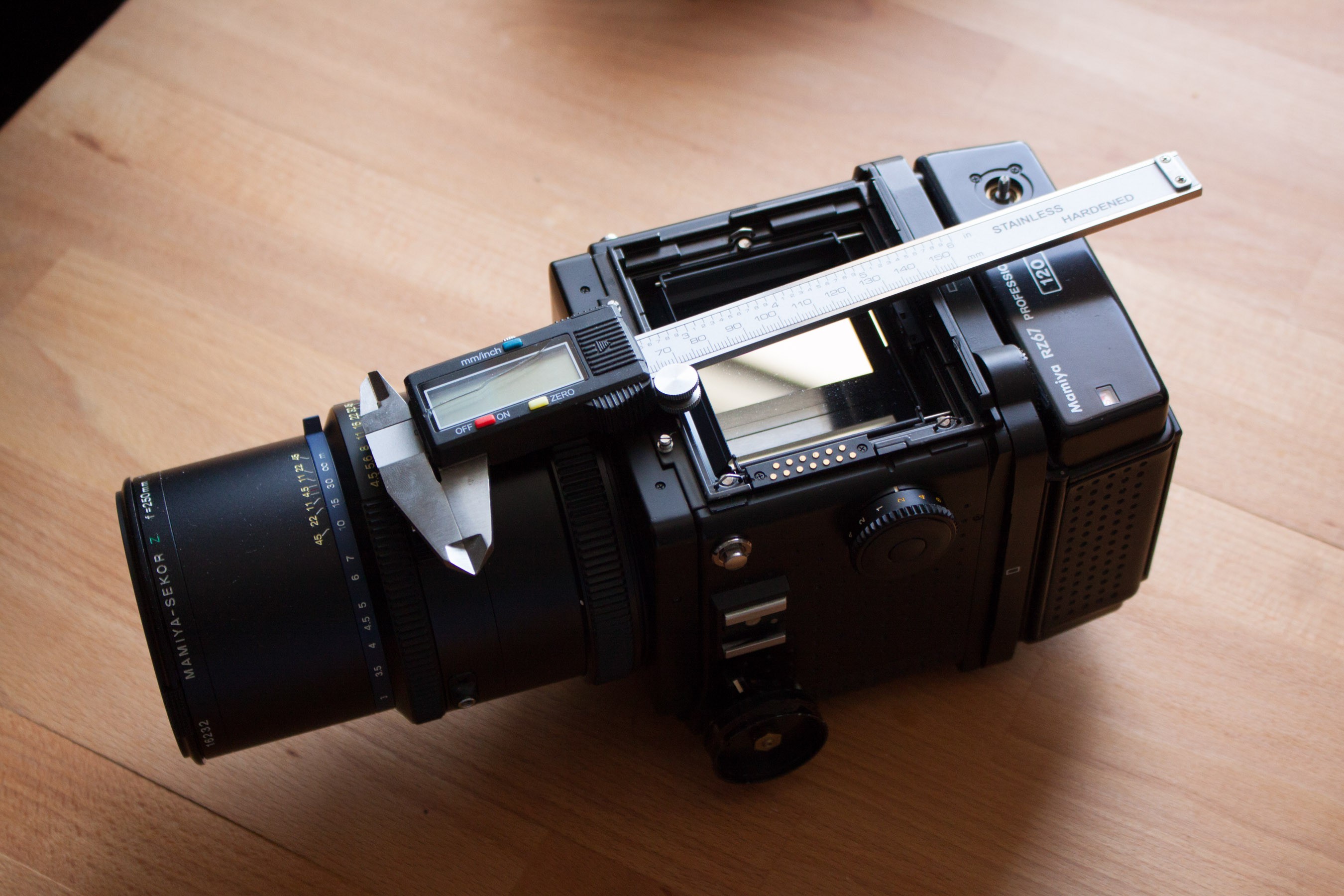
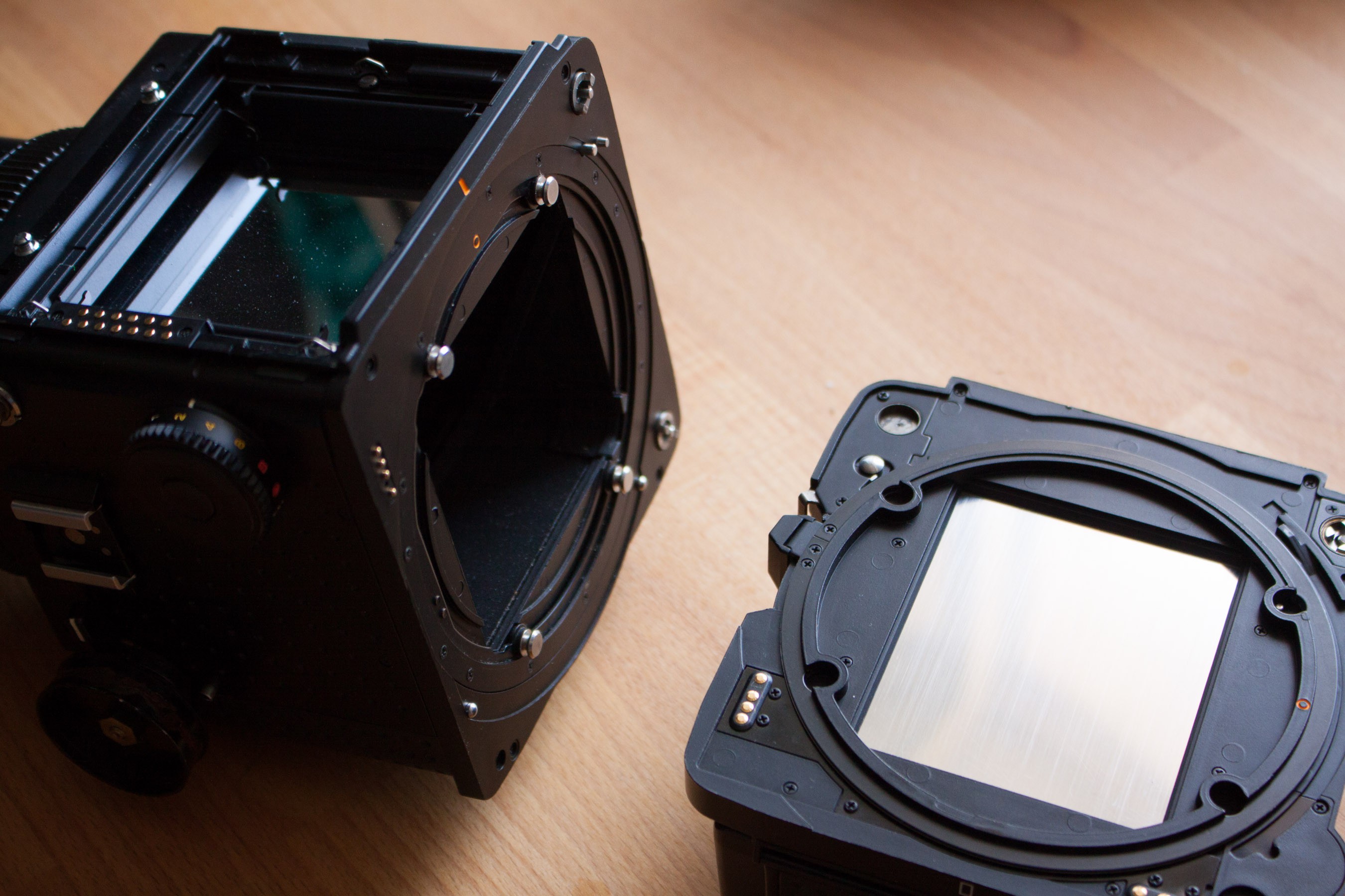
Mamiya RZ67 camera + lens + film back
Comared to any digital camera, even large DSLRs, this thing is huge. The viewfinder is 7x7cm large. A very unique and nice feature of this Camera is the rotating back. So a film back with 6x7cm area can be rotated to be used for portraits or landscape.
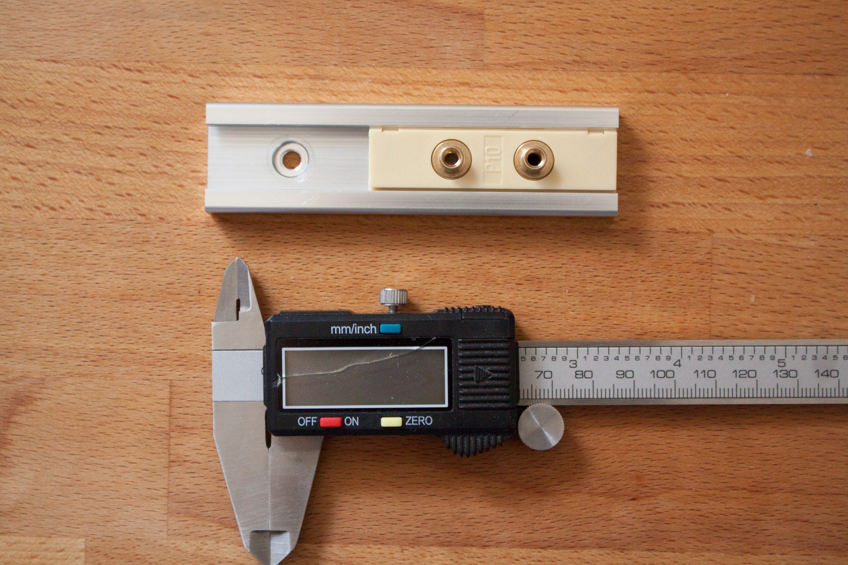
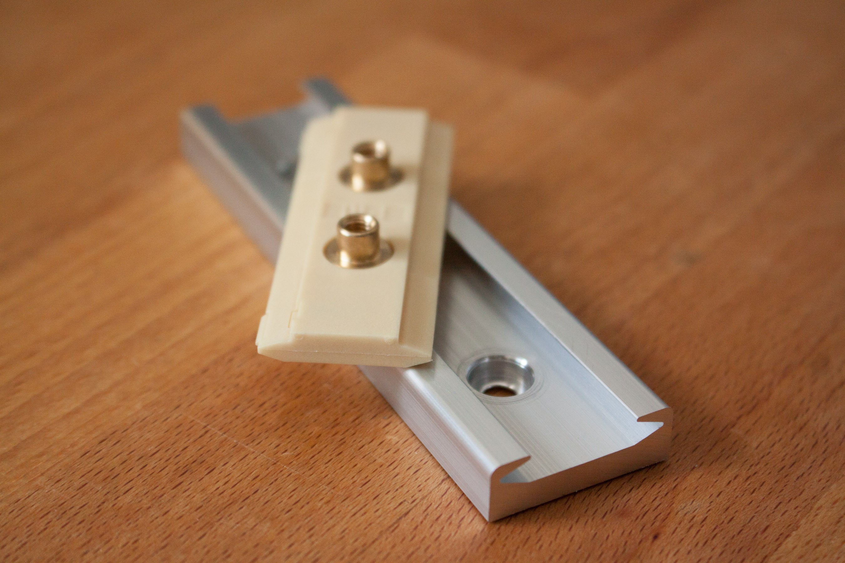
Linear guide rail
The used linear guide rail is a drylin N prism rail with 27mm width. The carriage has a 10N preload and runs very smooth. In the second image you can see the spring loaded part at the bottom left corner of the carriage. It pushes the carriage up and sideways, so when only a minimal mechanical force is applied it should be very precise movement.
Precise positioning of the sensor is very important, since the pixel-width and thus line width is only 8μm.

 Jacob David C Cunningham
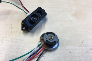
 JanThar
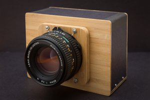
 Kevin Kadooka
 DeepSOIC
This is SO COOL!!!!! I’ve just seen a youtube video on something similar and really want to tr making my own. Any tips or tricks??? Thanks:)