The wiring is complete, and instead of making the first experiments with the old arduino due I decided to use the teensy 3.6 directly.
I have ported the code from the due sensor reading sketch and made a new one for the teensy 3.6. There was only a quick test if I get values from the sensor, but it looks good. Iterating through one line without using the ADC takes about 5ms, which is not so bad when you consider, that it's still using arduinos standard digitalWrite to bit-bang the signals for the sensor, and one line takes about 3200 clock cycles. When using the ADC to read one of the six output lines it takes about 26ms for one line.
Stepper movement and sd card writes are also working, so I really just have to put everything together and I should be able to get the first scans!
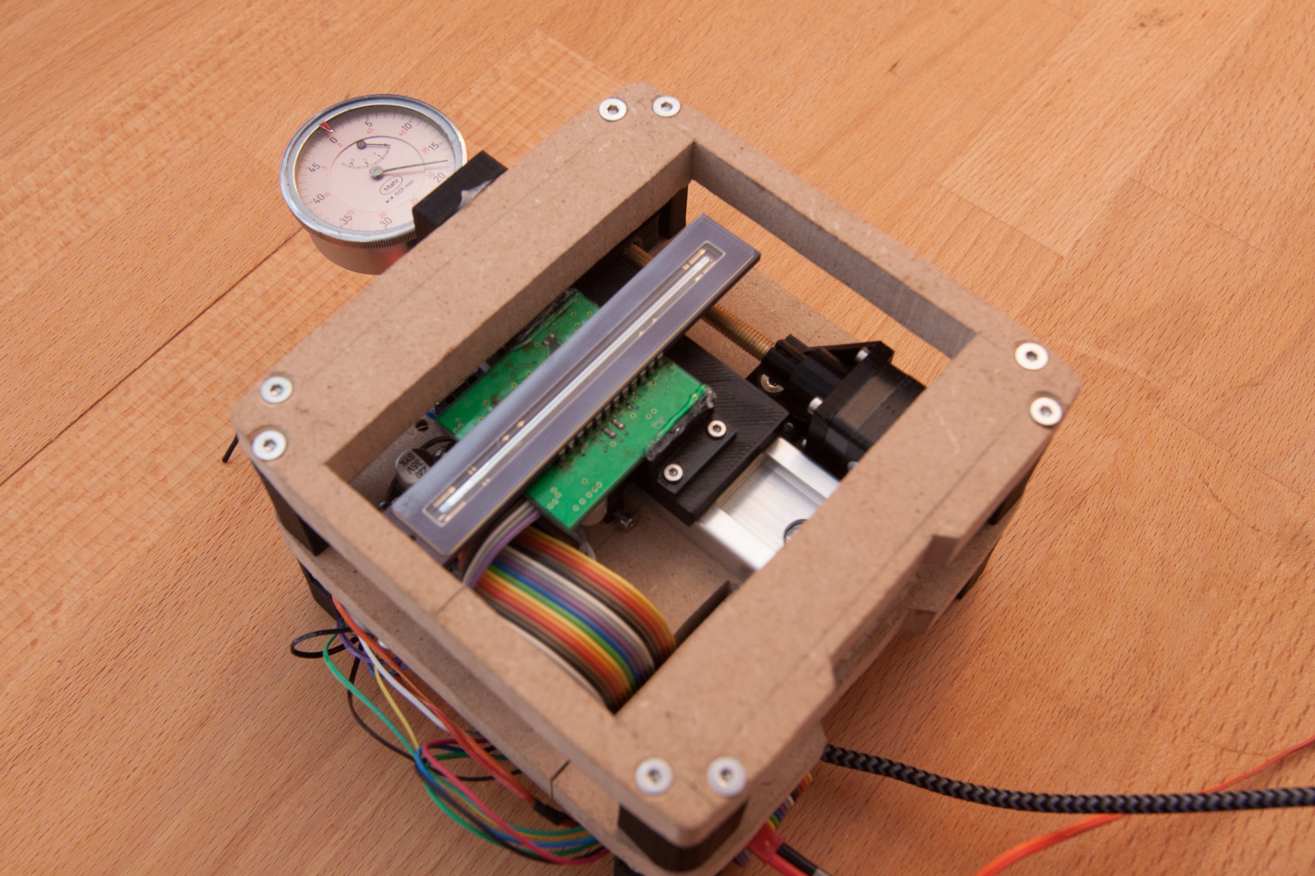
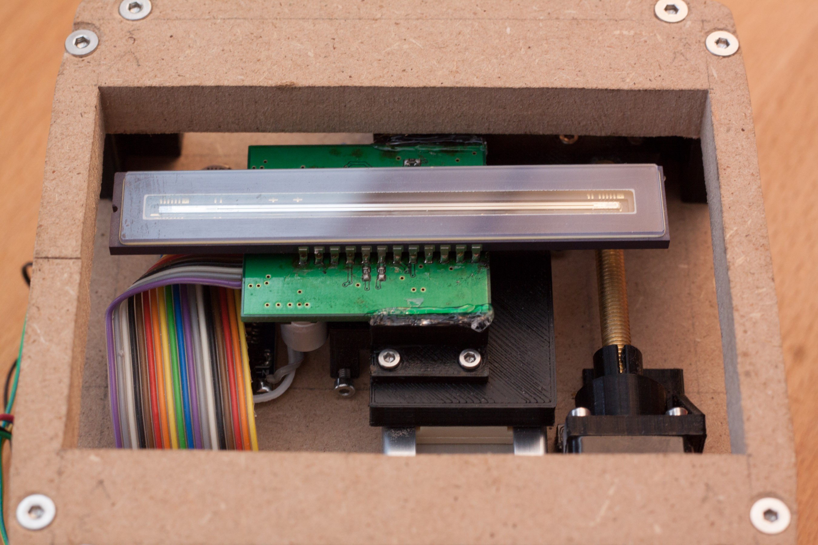
Mounted the sensor and finished wiring for first experiments. A dial indicator to verify, that the axis movement is precise enough can be seen at the top left.
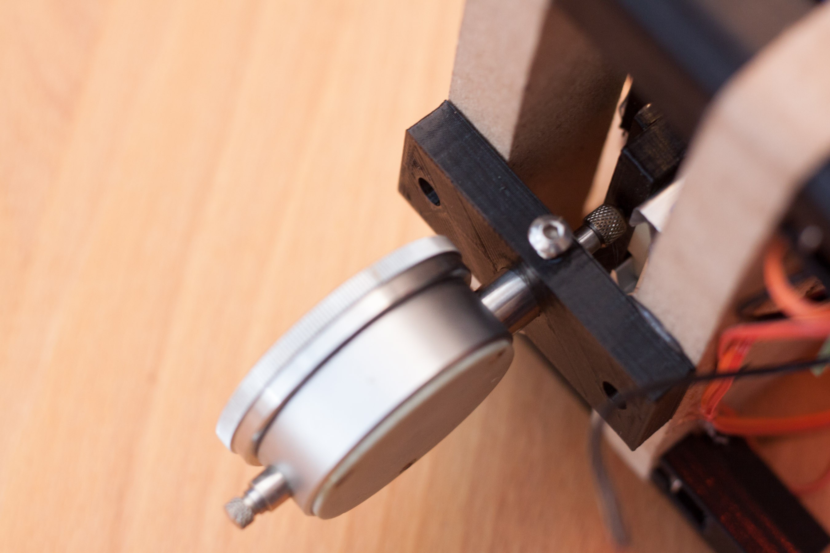
Detail shot of the dial indicators mounting, and where the carriage pushes against it.
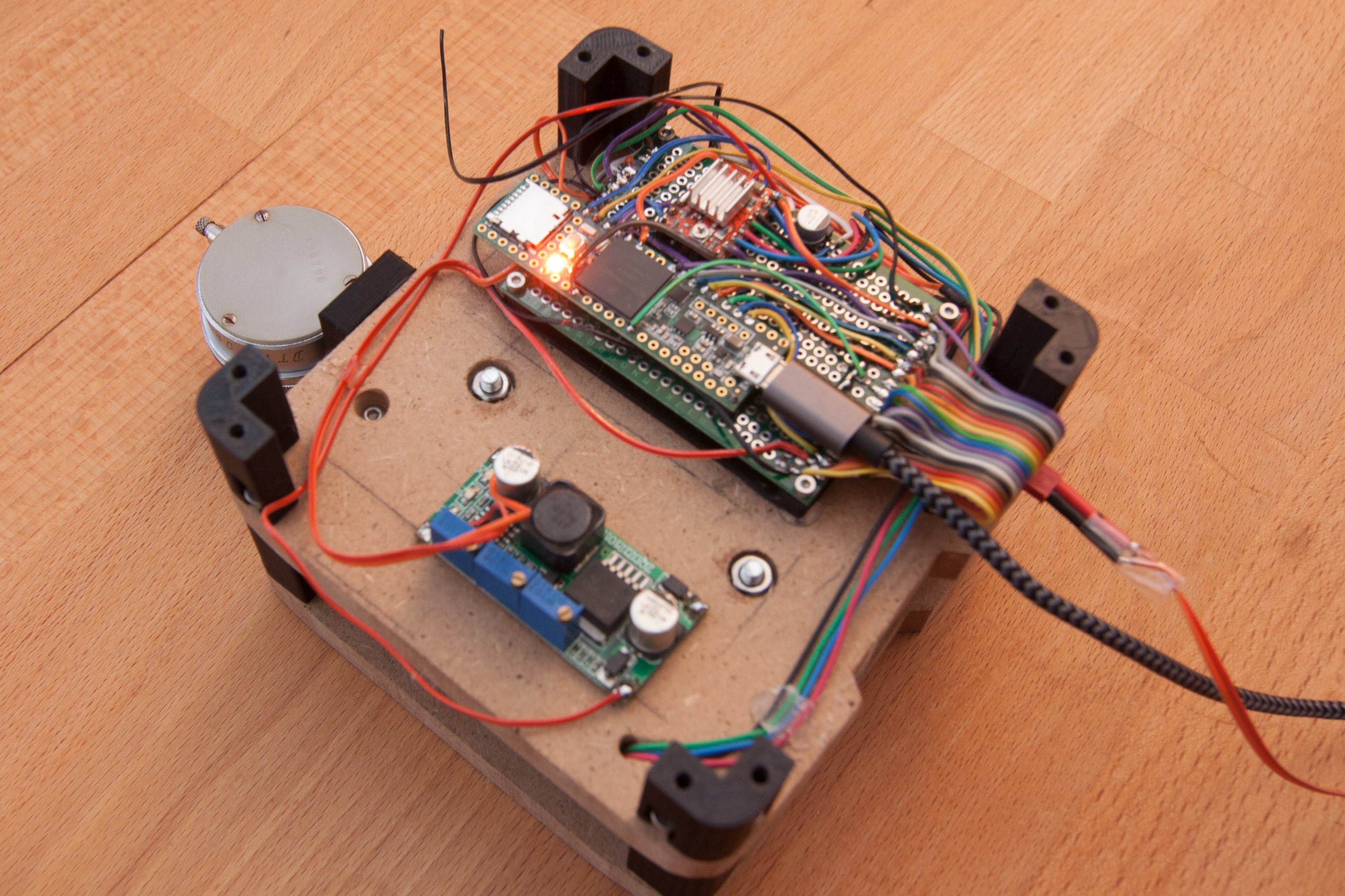
Wiring. It is not very pretty, but functional. The teensy and stepper driver have soldered to the perf board with only 4 pins each, this makes removing them later much, much easier. The connections are made on top of the pcb, because this way it is easy to make changes without removing the pcb. For prototyping this is very useful.
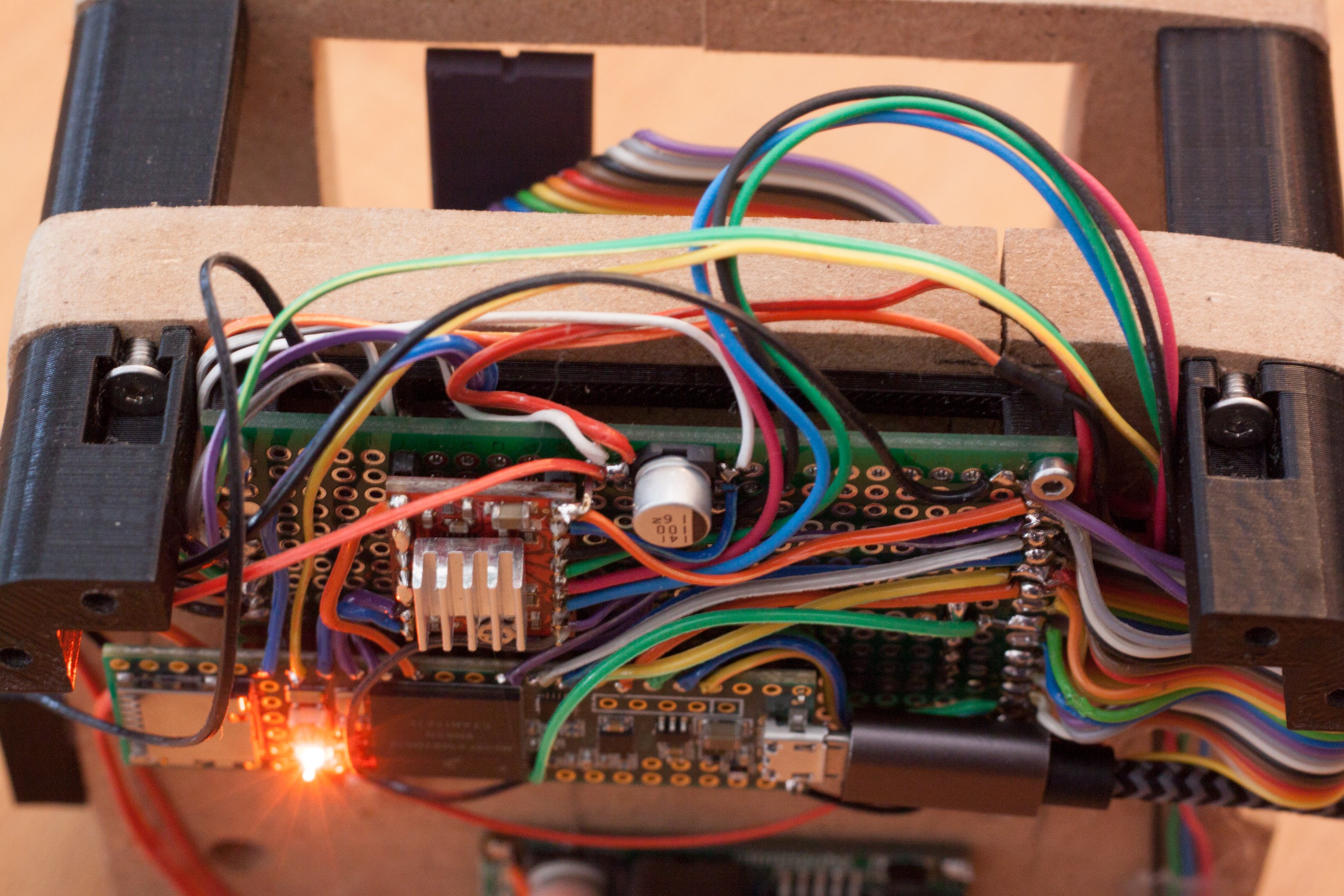
Detail shot of wiring. I tried to get the bent sensor cable into the picture. It starts at the sensor pcb (not shown) at the top, goes through the wooden mounting plate and is soldered to the right end of the perfboard.
Another picture of the sensor pcb and the sensors cable. Please excuse the hot-glue, I didn't have anything else on hand and it's better than a sensor dangling around.
With the mounted dial indicator I made a sketch that moves one step per second (until it hits the endstop). If you look closely, it seems like the dial moves about half a mark per step, which matches the desired 4µm per step. (One mark is 0.01mm or 10µm) Some steps seem to be a little larger or smaller, but in general it looks surprisingly good.
I also don't want to rule out measuring errors by the dial indicator, which doesn't feel very 'smooth' when pushed by hand.
Discussions
Become a Hackaday.io Member
Create an account to leave a comment. Already have an account? Log In.