 Pavel
PavelAs I tested the operations in simulation, I encountered the error in the design of Jump instructions, and thus the part of State Machine that is responsible for orchestrating execution of Jump instructions was not right. Here is updated state machine diagram with corrected error:
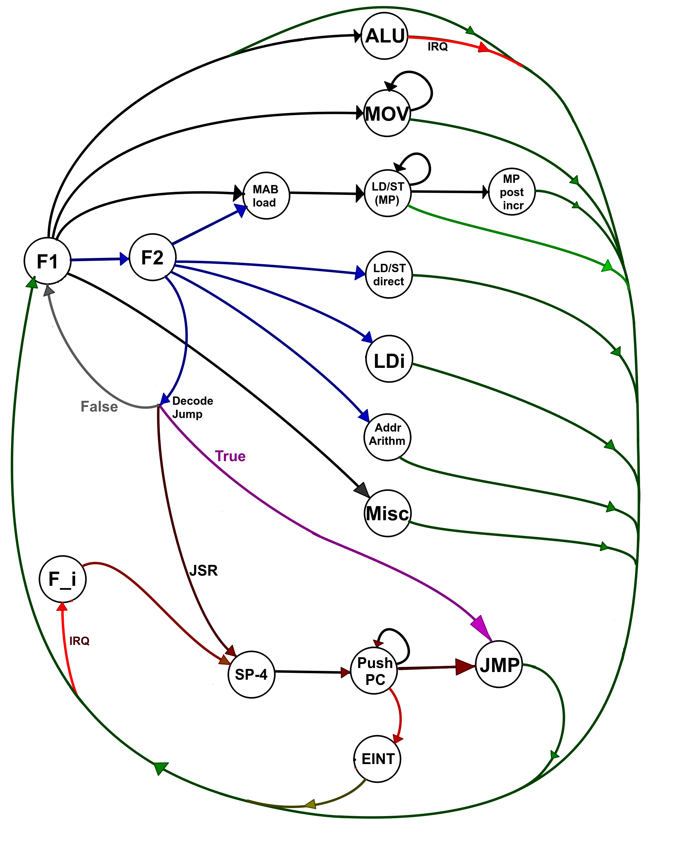
List of states:
01 - F1 -- Fetch 1 state, loads 16-bit word from memory at address in PC into Instruction Register, advances PC by 2; it is a common start of any instruction execution cycle.
02 - F2 -- Fetch 2 state, loads 16-bit word from memory at address in PC into Memory Data Buffer Register, advances PC by 2; it is used for 2-word instructions, second word containing some immediate value.
03 - F_i -- Fetch Interrupt state, loads hardcoded JSR (SP) [r0] instruction into Instruction Register. The execution is modified so that [r0] value is ignored. This state is entered when IRQ signal is set, and current instruction is executed fully.
04 - ALU -- ALU state, perform any of the 29 ALU operations on GPR. This state is normally staggered / concurrent with F1 state. In case there is an IRQ signal active, the next instructions Fetch state is entered only after current ALU state is executed.
05 - MOV -- MOV state, Copy data from one register in CPU to another, can be repeated several times for multi-word transfers.
06 - MAB load -- during this state, the 32-bit Memory Address Buffer is loaded with sum of value from MP and offset; for loads/stores with pre-ncrement the Memory Pointer is also updated with this value.
07 - LD/ST (MP) -- load or store value from memory at address in MAB to register, advance MAB by 2; can be repeated several times for multi-word memory transfers.
08 - MP Post incr -- Updates 32-bit Memory Pointer Pair with sum of its current value and signed 16-bit offset.
09 - LD/ST direct -- Loading/storing 16-bit value from memory at immediate address (provided from combination of low byte of Instruction Register and Memory Data Buffer register).
10 - LDi -- Loading of 16-bit value from Memory Data Buffer register into one of the GPR, or sign extended 25-bit value from combination of low 9 bits of Instruction Register and Memory Data Buffer register.
11 - Addr Arithm -- Address Arithmetic, Loading 32-bit MP with sum of its current value and signed 16-bit offset.
12 - Misc -- Any of 8 unsorted instructions that are executed in one clock cycle.
13 - JMP -- Jump, Loading 32-bit PC with sum of its previous value and signed 16-bit offset.
14 - SP-4 -- Loading 32-bit SP with its current value minus 4, also storing this new value to 32-bit Memory Address Buffer.
15 - Push PC -- Store PC register pair to memory at current address in MAB, update MAB with its current value plus 2. This state is repeated 2 times, storing high and low halves of PC.
16 - EINT -- Enter Interrupt, or Jump to Interrupt Service routine, Loads PC with current value from Interrupt Vector register, clears IRQ signal.
Discussions
Become a Hackaday.io Member
Create an account to leave a comment. Already have an account? Log In.