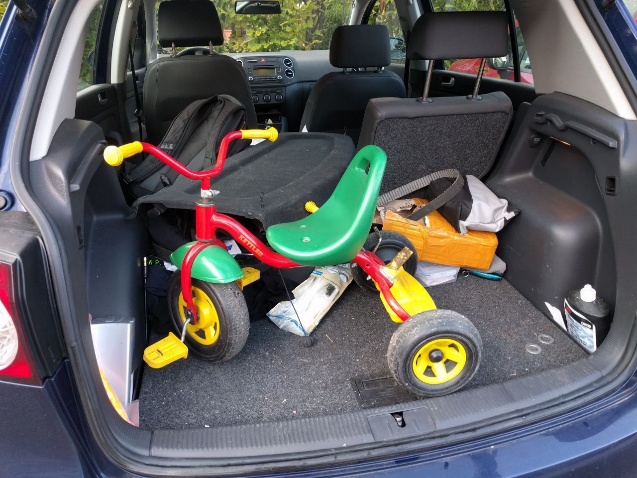
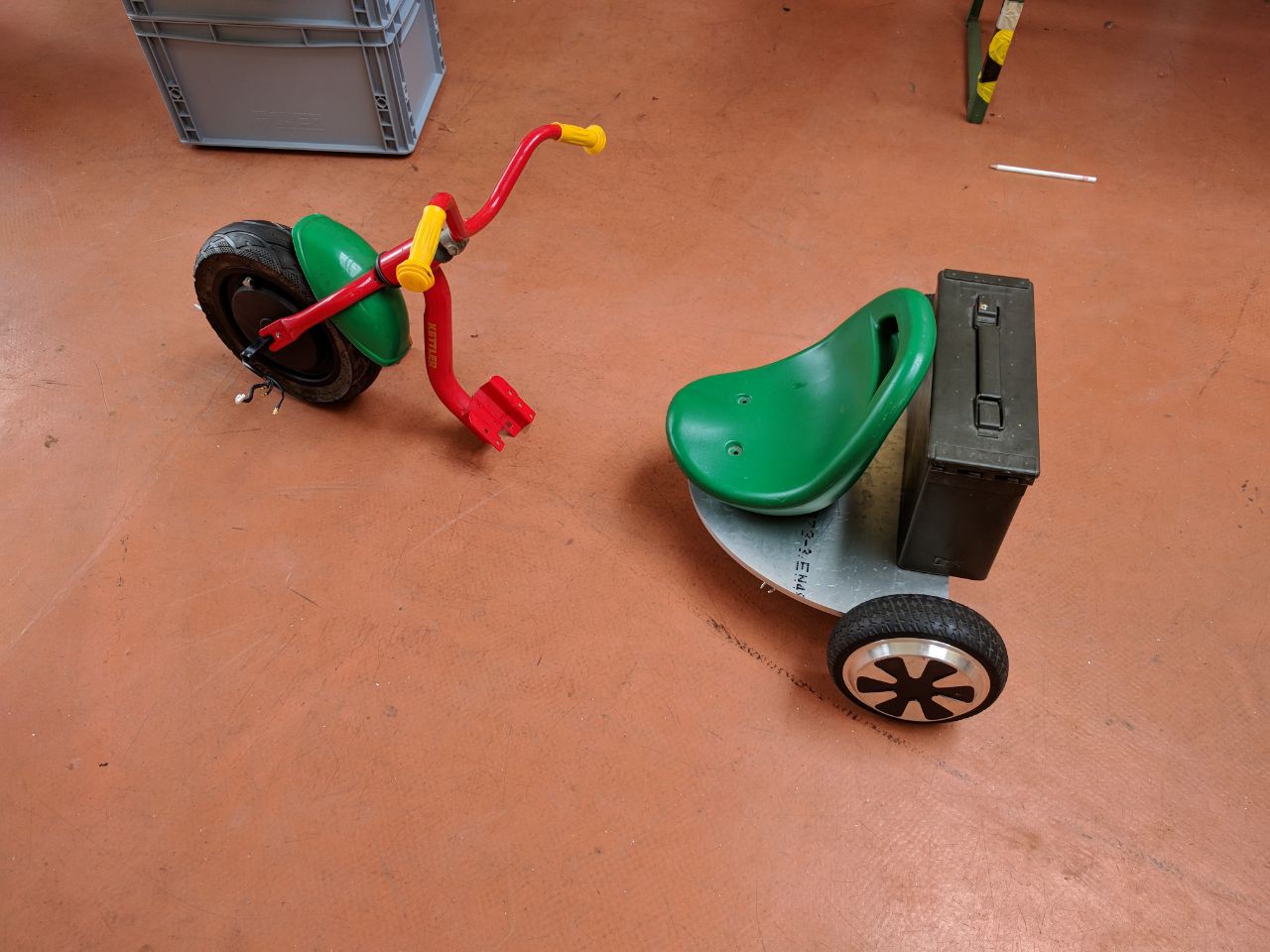
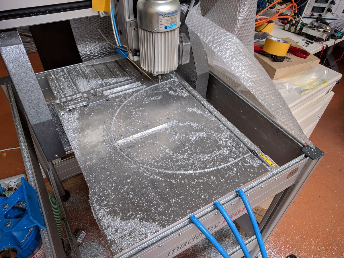
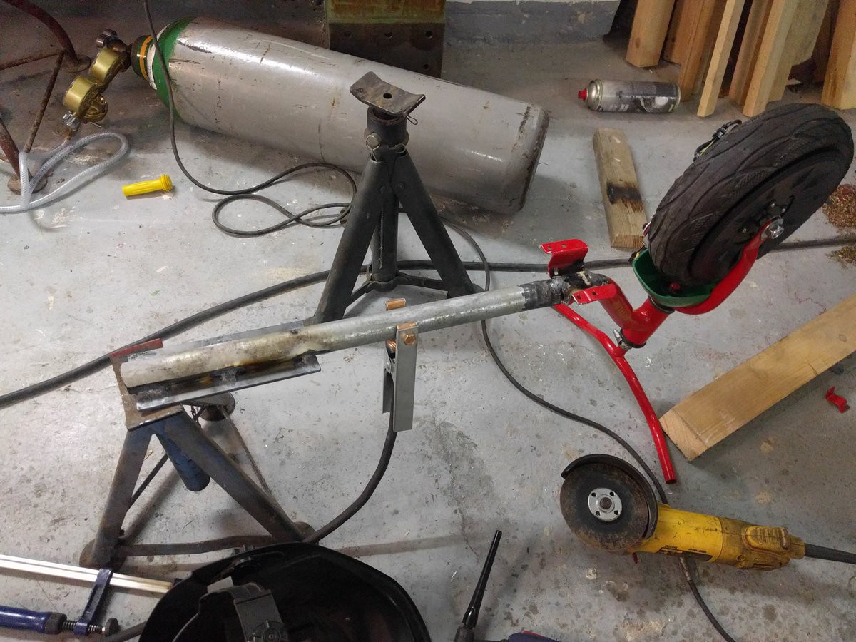
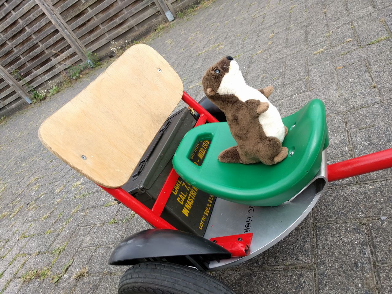
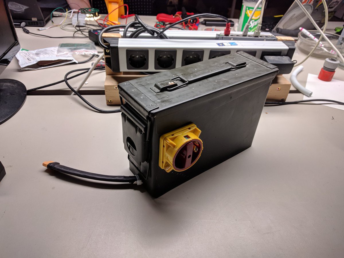
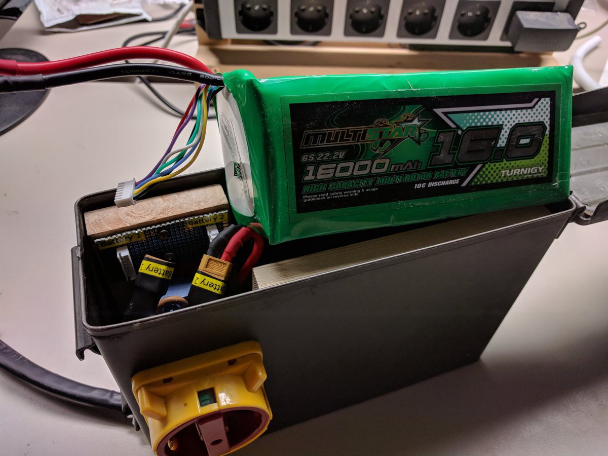
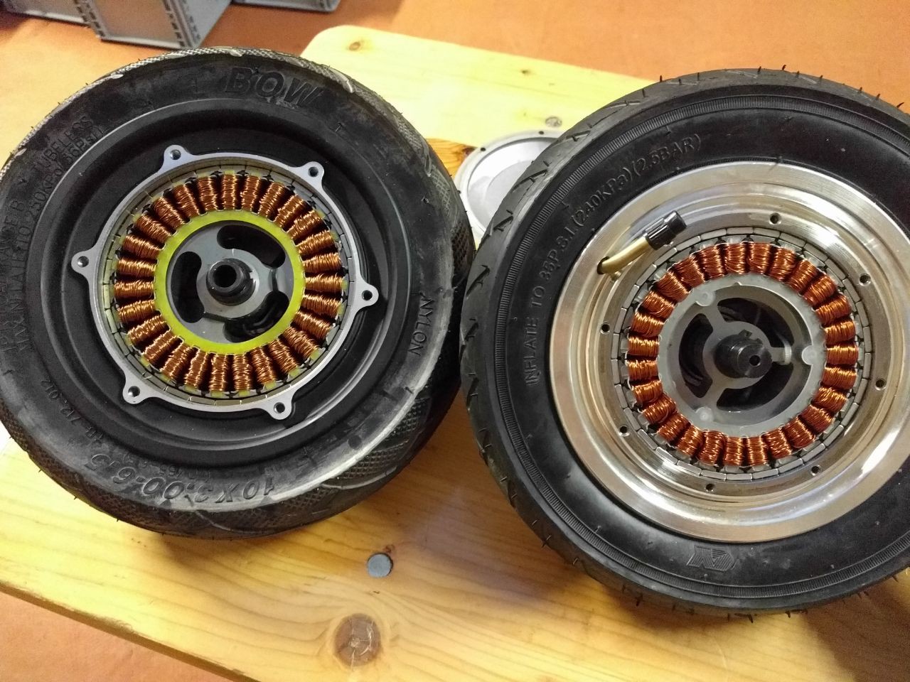
• Overview

    Lucy Fauth08/21/2018 at 14:53 1 comment

    Two weeks before the EMFcamp 2018 I learned on Twitter about Hacky Racer. And because I'm quite into moving objects, I had to join the race. I already have some moving objects, a BobbyCar, a moving armchair, but all of these are rather unpractical to comply with the Rules of HackyRacer.

    Frame

    So I decided to build something new. I had anything I could possible need laying around, like tons of hoverboard motors, ESCs, batteries... All I needed to buy was a kids toy:

    I wanted to have all-wheel drive, because why not. On the same day I started planning the vehicle:

    It had to comply with the rules of HackyRacer, and one of them is that the batteries need to be contained in a metal box. That is what the ammo box on the back is used for. Apart from that, I replaced the front wheel with a BLDC motor of a Ninebot Mini Scooter, and milled an aluminium sheet as the main body to sit on:

    Then I welded a longer steel pipe onto the existing frame of the kids tricycle and added a better seat from a broken chair.


    Battery

    Usually to get highest possible speed I would have used a 13s (13x 3.8V = 49.4V) LiIon battery for this tricycle. However, per rules a maximum voltage of 48V is allowed. To I decided to go with 12s 16Ah LiPo. Also per rule, there must be a main switch to completely turn of the vehicle. So I added a 400VAC 25A machine switch to the battery box. This is a 3ph switch, so it has 3 switching contacts. I connected them all in series to ensure safe circuit braking in case there is an arc between one of the contacts while opening under load. Also there is a generic protection pcb inside the box that monitors the individual cell voltages and does some balancing during charging.


    Motors

    For everyone who knows me, it is probably obvious what motors I used for this tricycle. I did lots of hoverboard hacking during the last year, so I still have lots of these motors laying around. They are very great because they are cheap, they are really reliably and tough, and they have lots of power. These typical hoverboard motors come in three sizes, 6 inch with solid rubber, 8 inch with solid rubber, and 10 inch with an air tube. They all have 350W at 36V so depending on the size you get more or less torque, but also more speed for bigger diameters. At 12s however you can get more than 1000W out of these motors for a short period of time. Of you overload them for too long, the copper winding burns or the internal hall sensors start to desolder.

    For the back, I wanted to have the air tubed wheels because I have no other shock absorption and it would probably be quite hurtful to have an offroad race with the solid rubber wheels. Unfortunately I only had two of these left so I had to use a wheel of a Ninebot scooter. These are identical to hoverboard motors on the first glance, however when I configured the ESCs I noticed the motor parameters are quite different and the current PID that worked fine for hoverboard motors started to oscillate. Also, after fixing this, the motor still was way slower than the hoverboard motors (420rpm vs 730rpm at 48V without load).

    After some research I found out that these Ninebot scooters run at 15s batteries, and turning apart one of the wheels also revealed that they are indeed a bit different:

    (Left Ninebot, right generic hoverboard motor)

    That ninebot motor (left) definitely has more copper in it than the hoverboard motors. Unfortunately that doesn't reduce resistance, it rather adds some more windings to match the higher battery voltage. Nice if you drive it with 60V but a huge disadvantage for 12s operation. More windings at given parameters = more back EMF. More BEMF means that at a given speed and given voltage, you get less current in the motor. Vice versa at a given voltage, the speed at which motor current is zero because back EMF = VBUS is less with more windings. Luckily, there is a simple solution...

    Read more »