 Matt Bradshaw
Well, rather excitingly, I was one of the winners of the musical instrument category! This means I'm now doing a last-minute scramble to make sure my project is fully documented ready for the finals deadline. Accordingly, here are lots of photos of my synthesizer, inside and out.
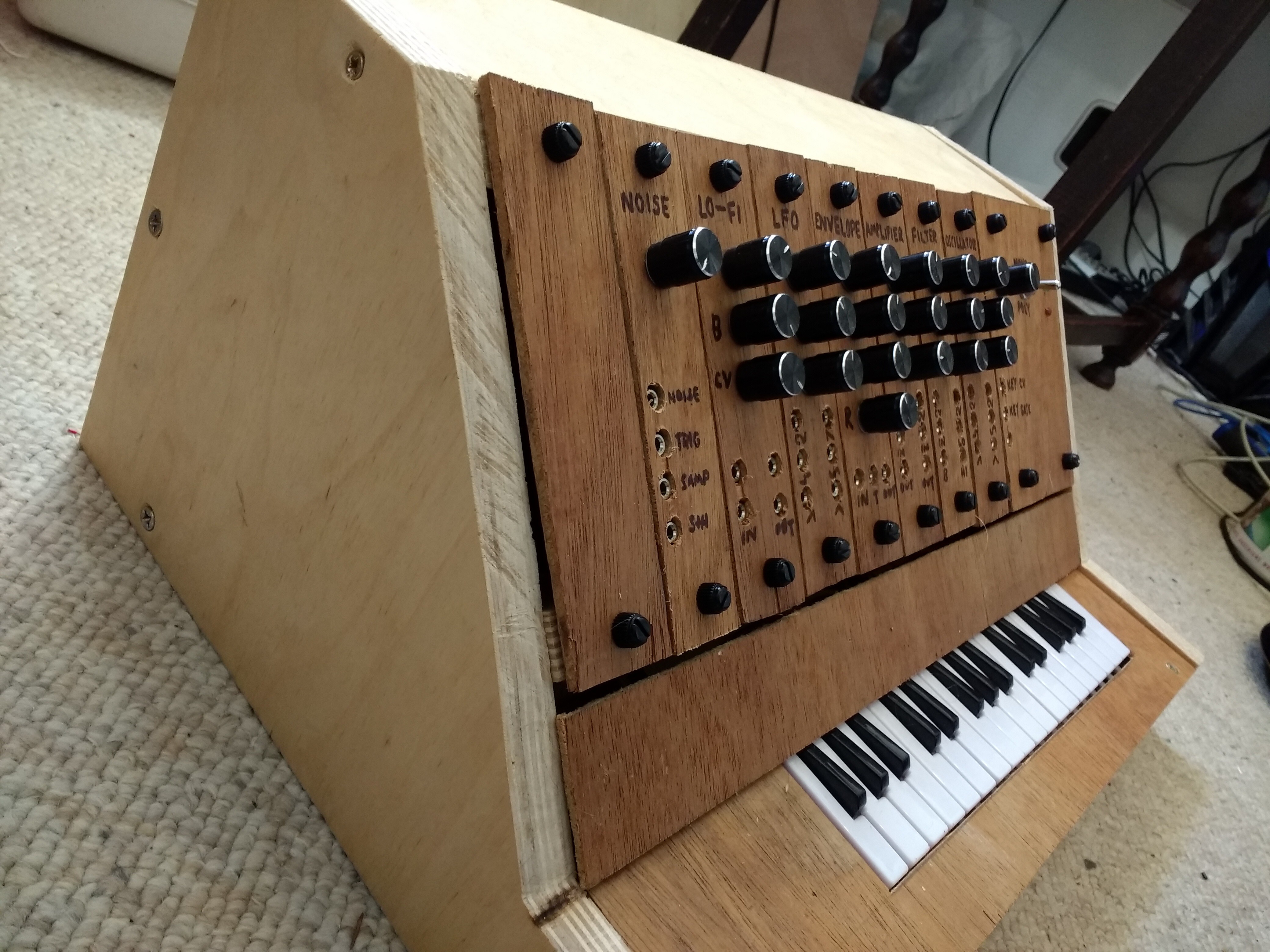
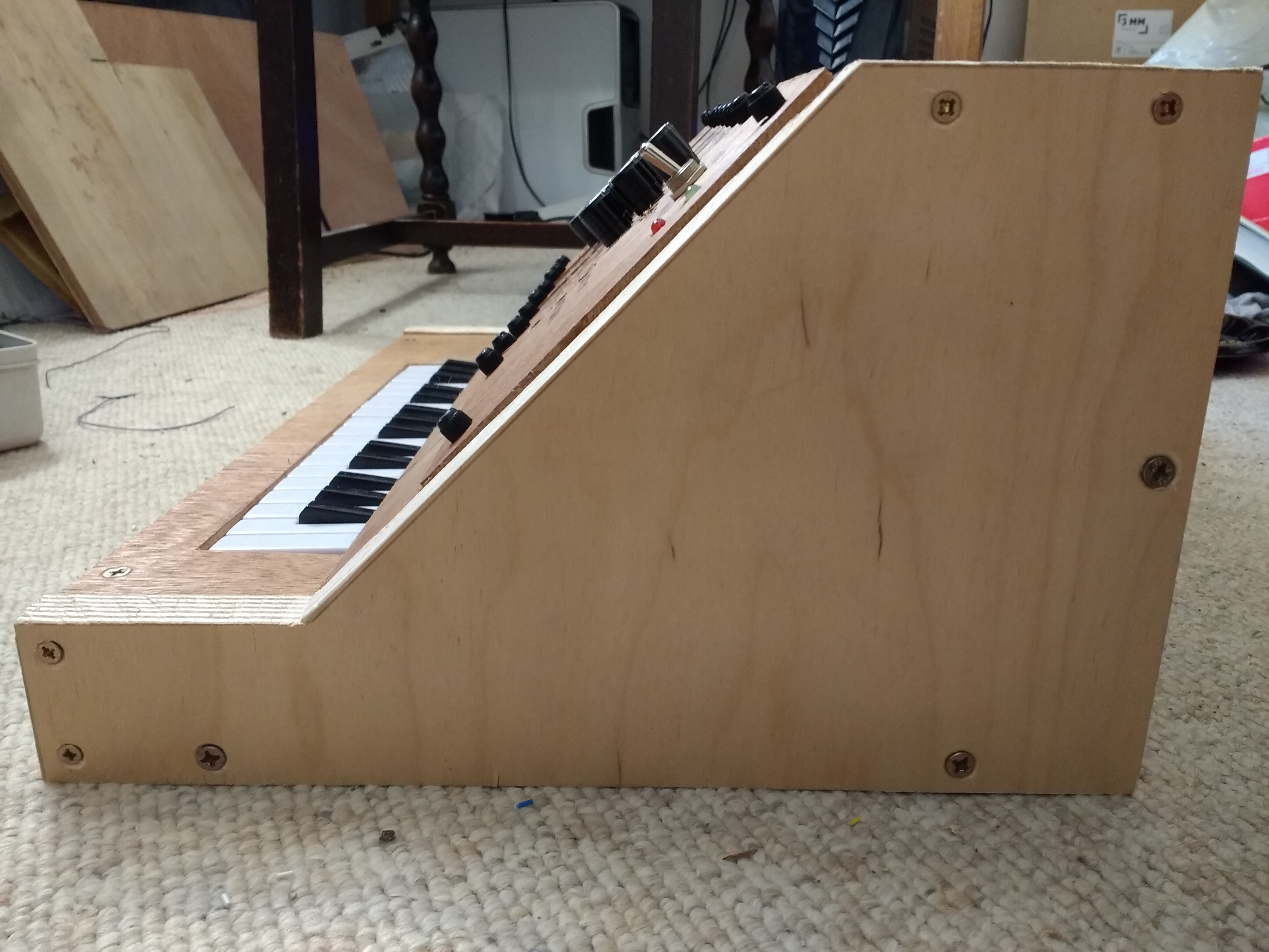
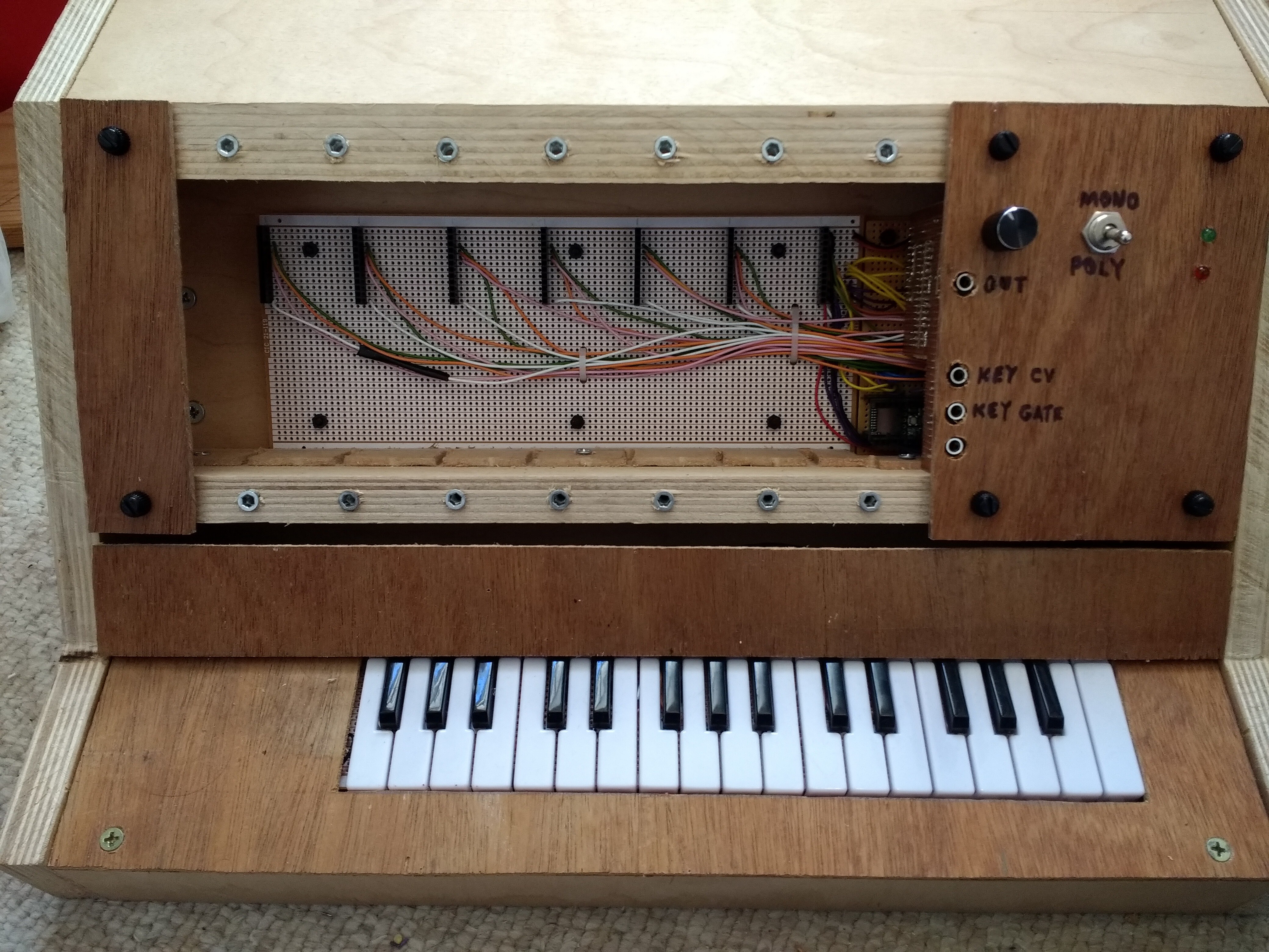
This is the synth with all its modules in place, ready to play, viewed from a few different angles:
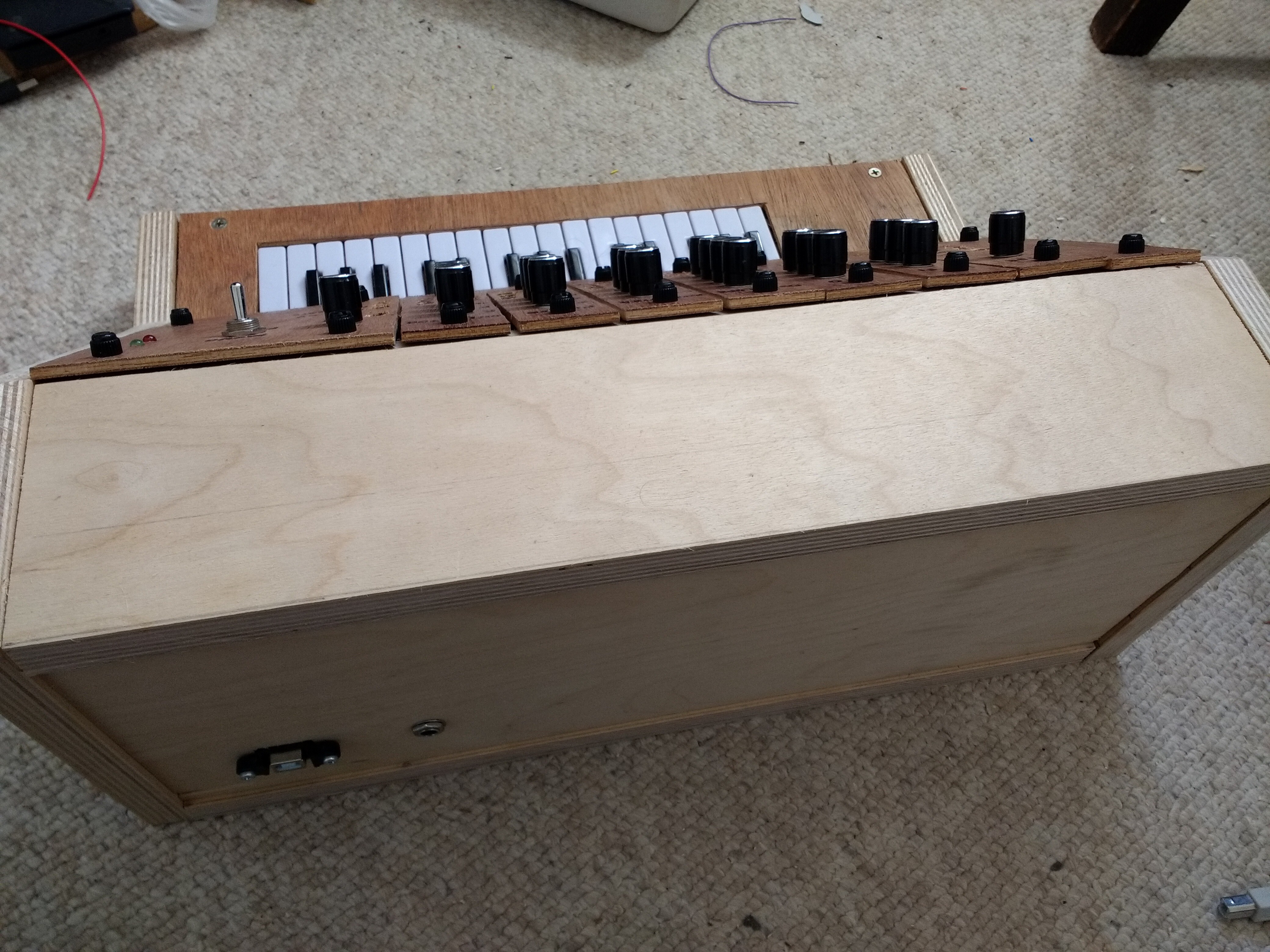
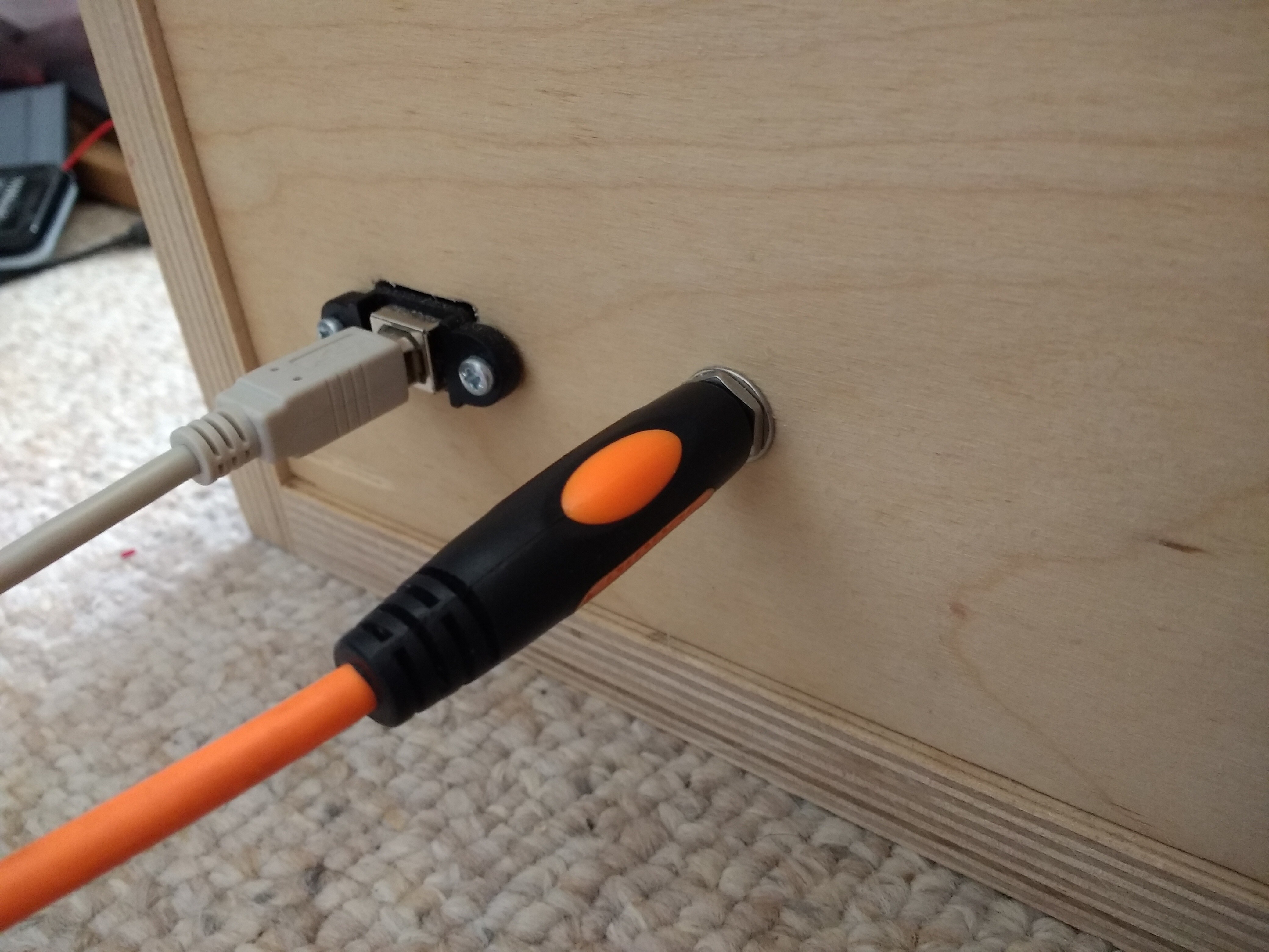
There are two sockets on the back: a standard 1/4" audio output jack, and a USB power input, which can also be used to upload new code to the Teensy.
This is what the synth looks like it with no modules in it. Note the metal threaded inserts at the top and bottom, which allow the modules to be securely screwed in place, and the slotted wooden section just below the white circuit board, which helps to align the modules.
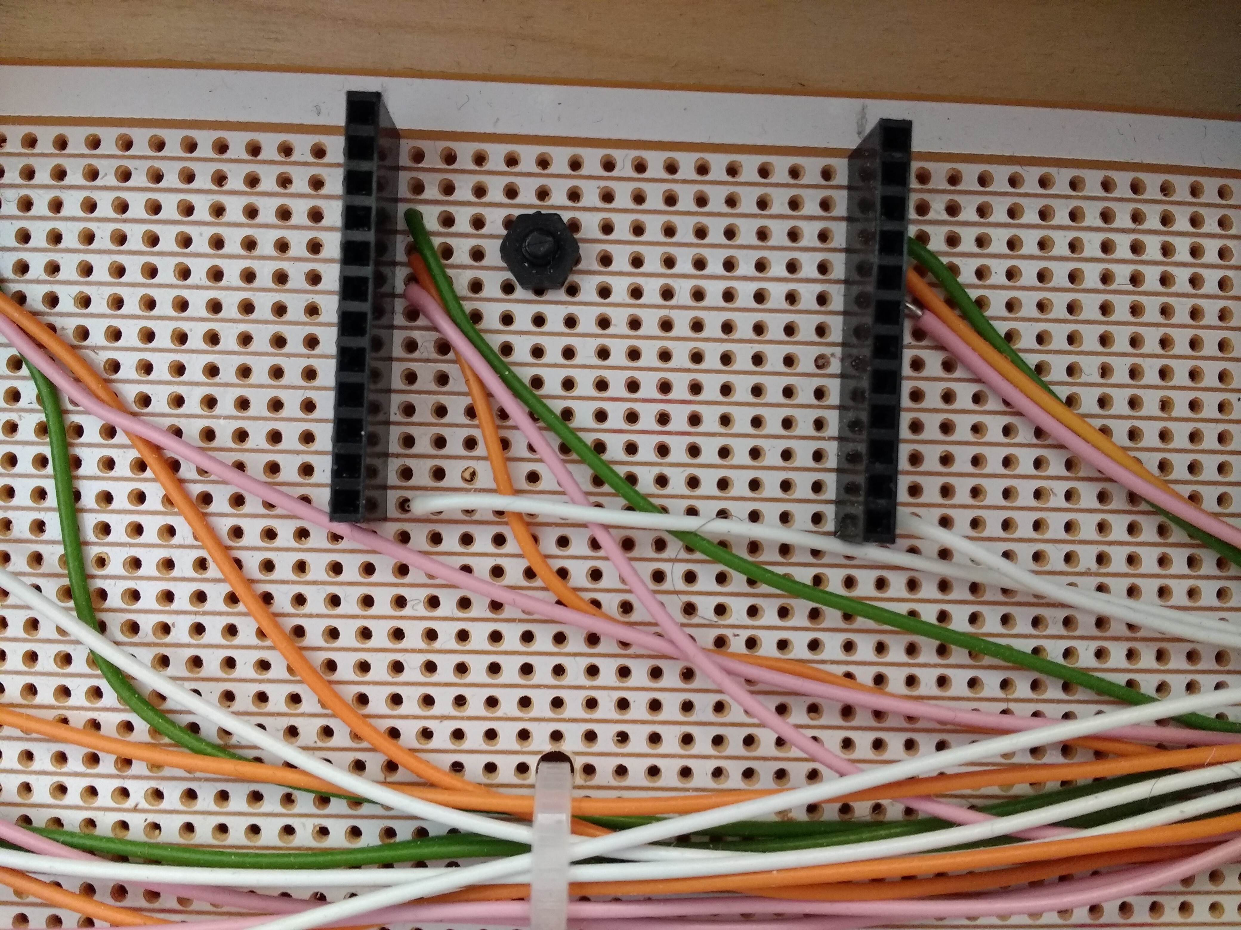
Here is a close-up of the 12-pin module headers. This circuit board is mounted on nylon standoffs.
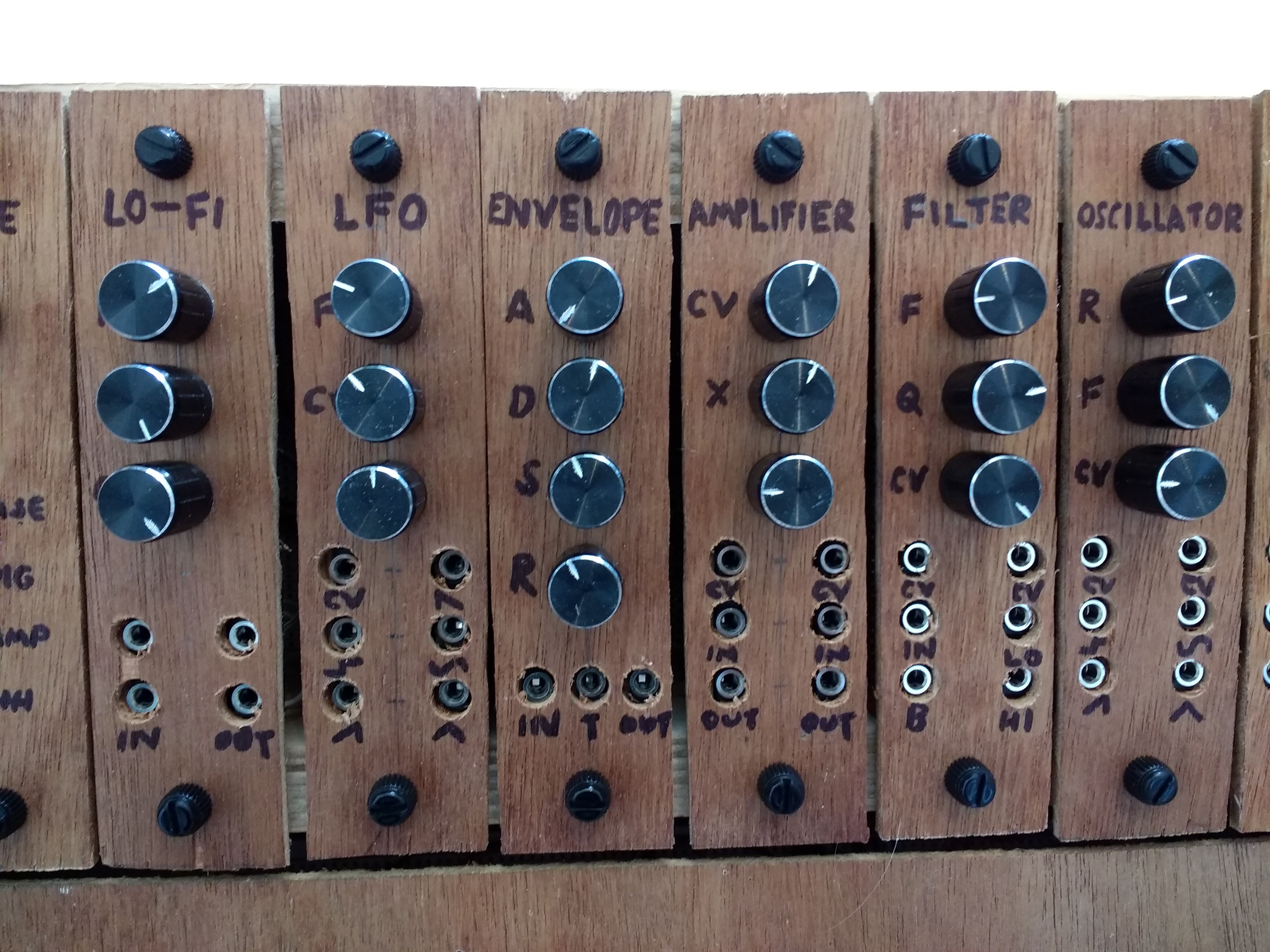
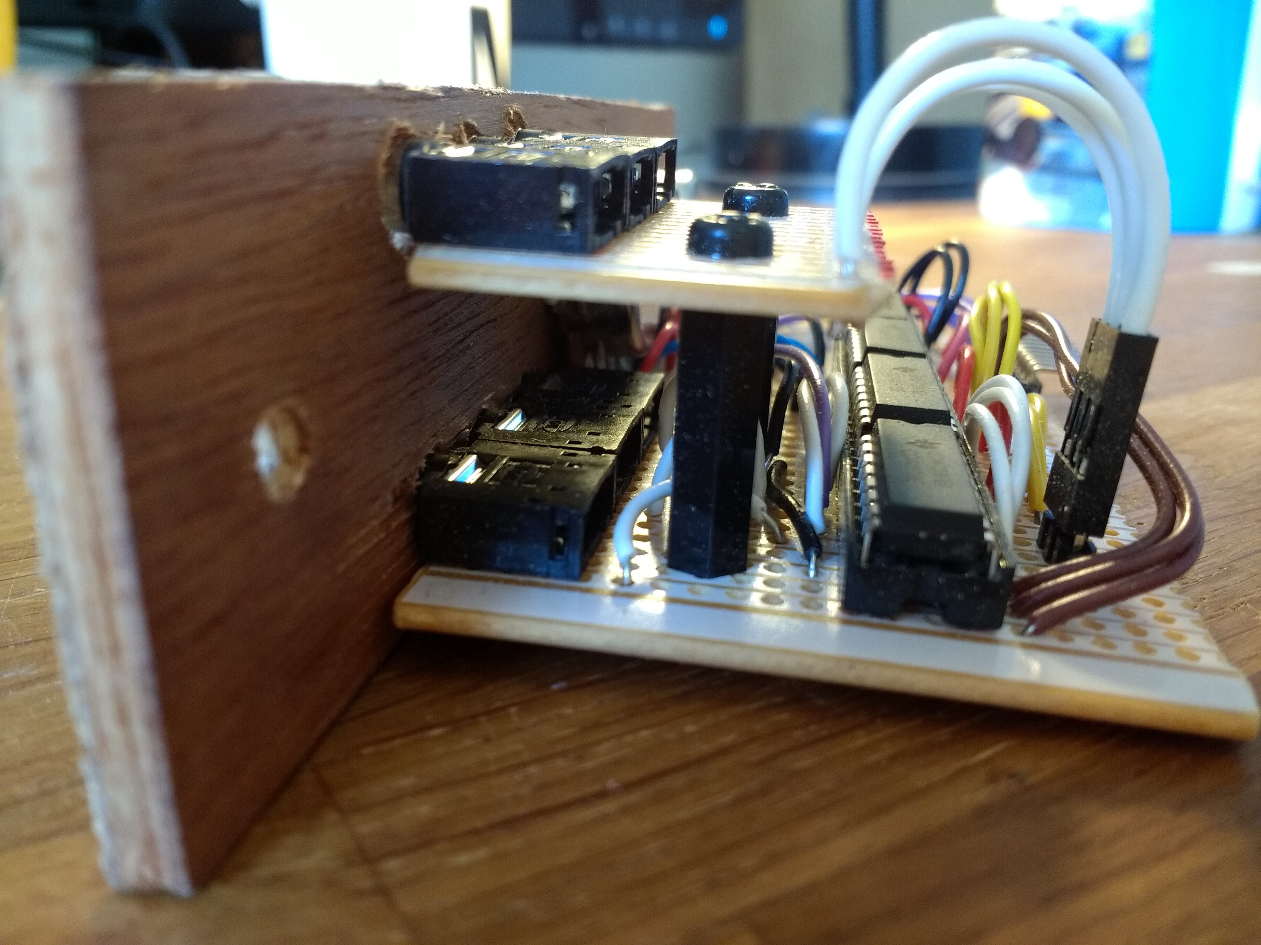
Here is a typical module (this one is a filter) with three knobs and six sockets.
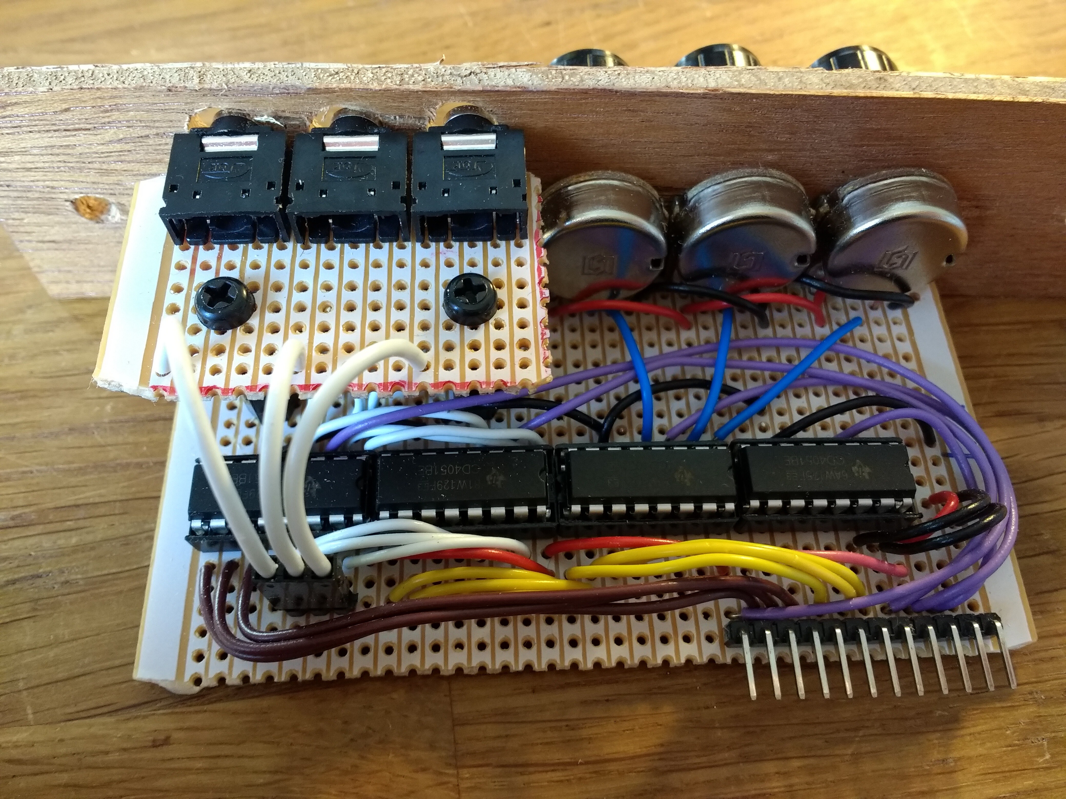
Viewed from another angle, you can see how the second row of sockets is mounted using nylon standoffs.
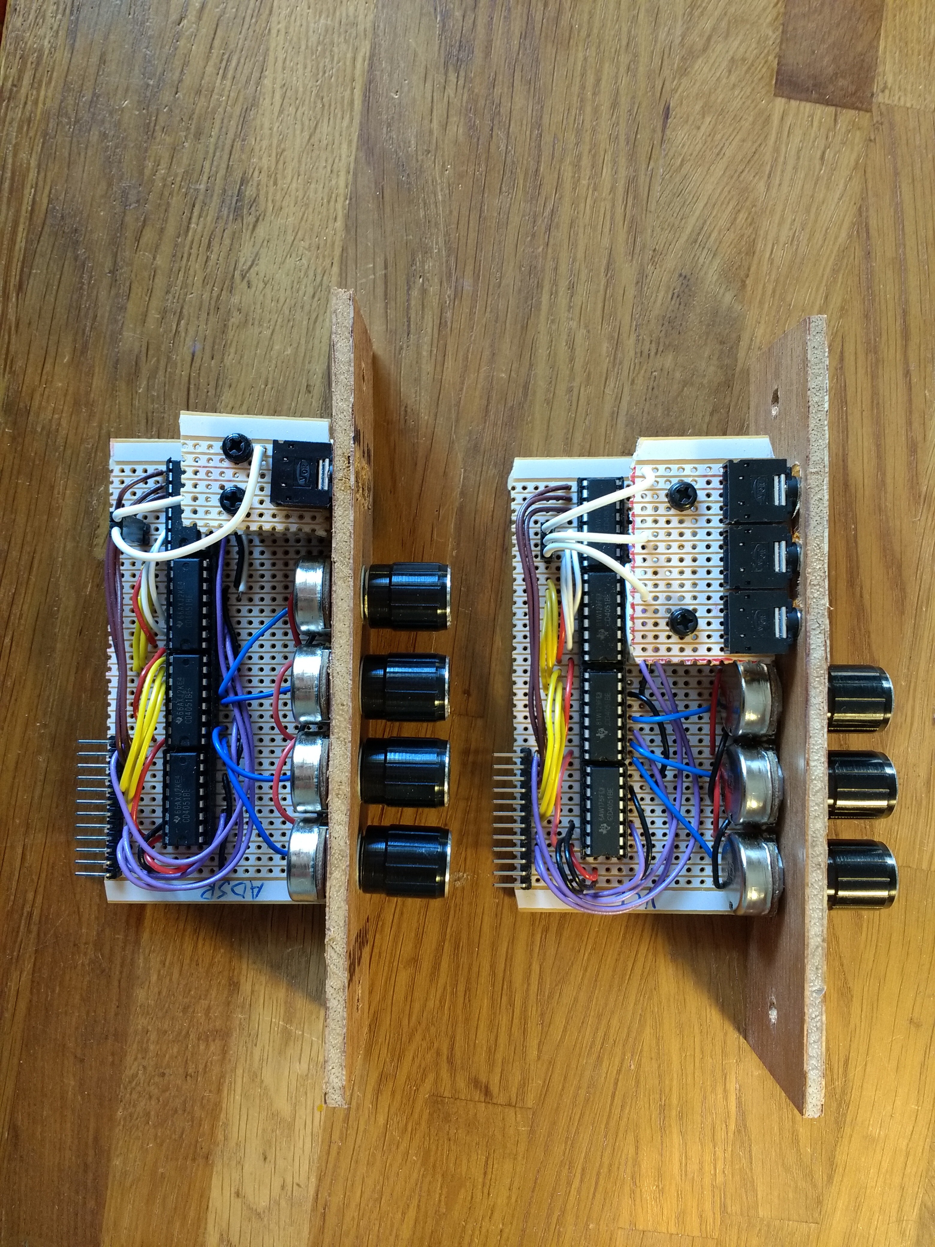
I took a photo of two modules side by side to demonstrate that there is almost no difference in circuitry between different modules. The only thing that really changes is the layout of the knobs and sockets.
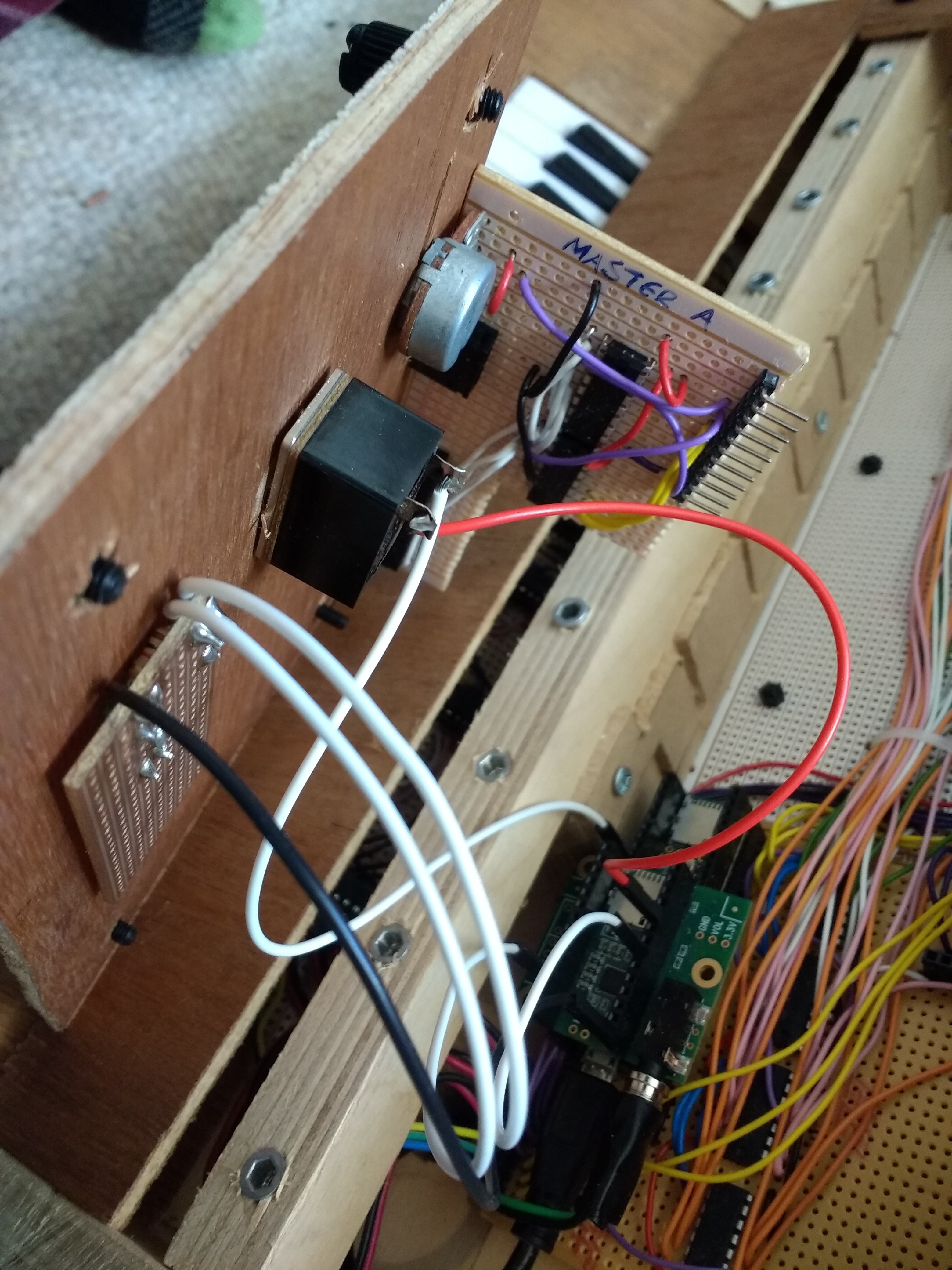
Back inside the synth now, this photo shows the back of the master module, which has a monophonic/polyphonic toggle switch, a volume control and a couple of LEDs. The unusual L-shaped board was a compromise to allow the Teensy to sit below the master module - I will change this in the future.
And here's a photo of the main circuit board, which is basically just a Teensy (with an audio board) and four 4051 multiplexer/demultiplexer ICs. The overwhelming number of wires (which mainly communicate with the modules) is a weakness of the design. I hope to solve this in my next prototype, which is very likely to use a proper PCB rather than stripboard!
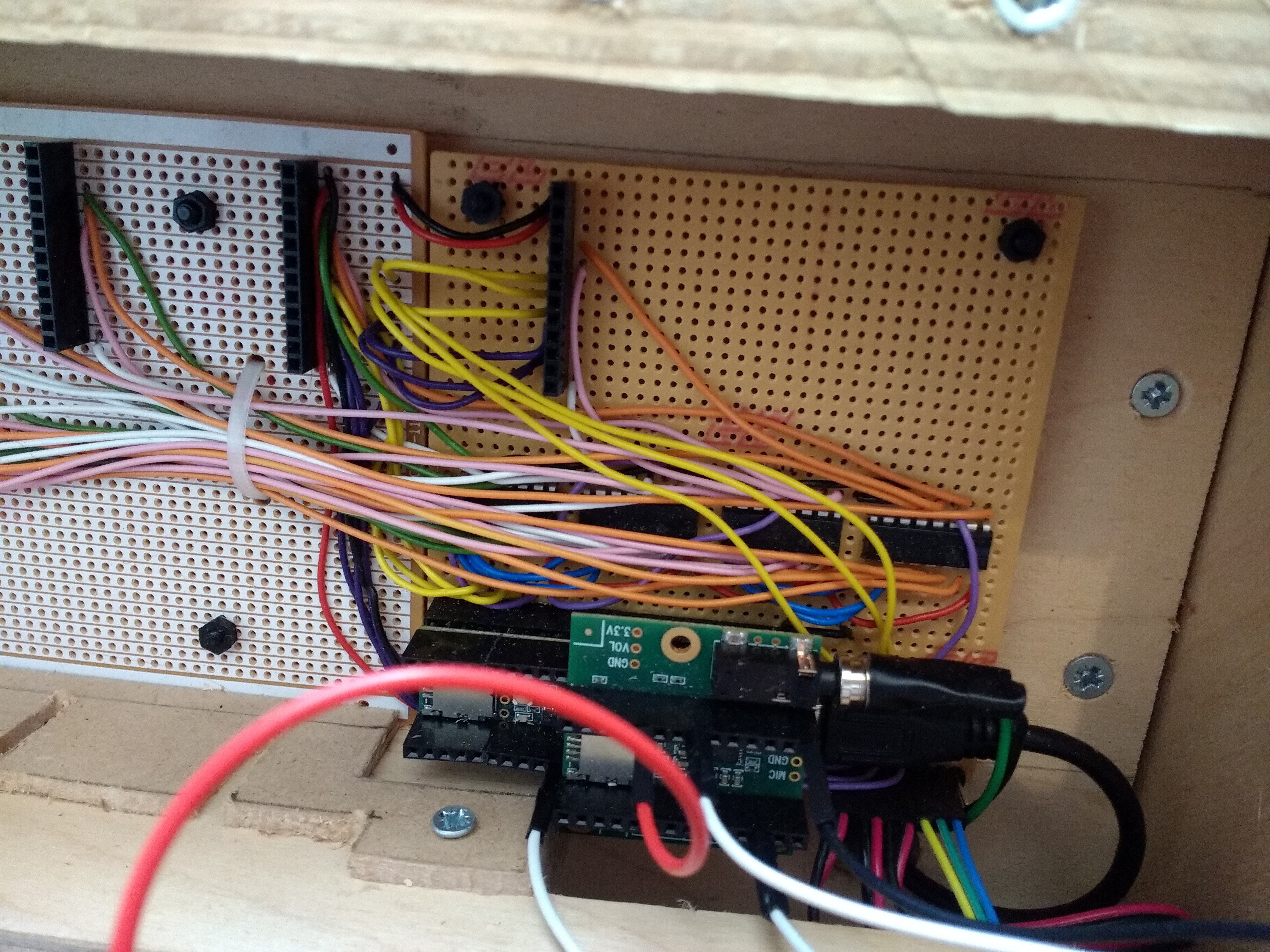
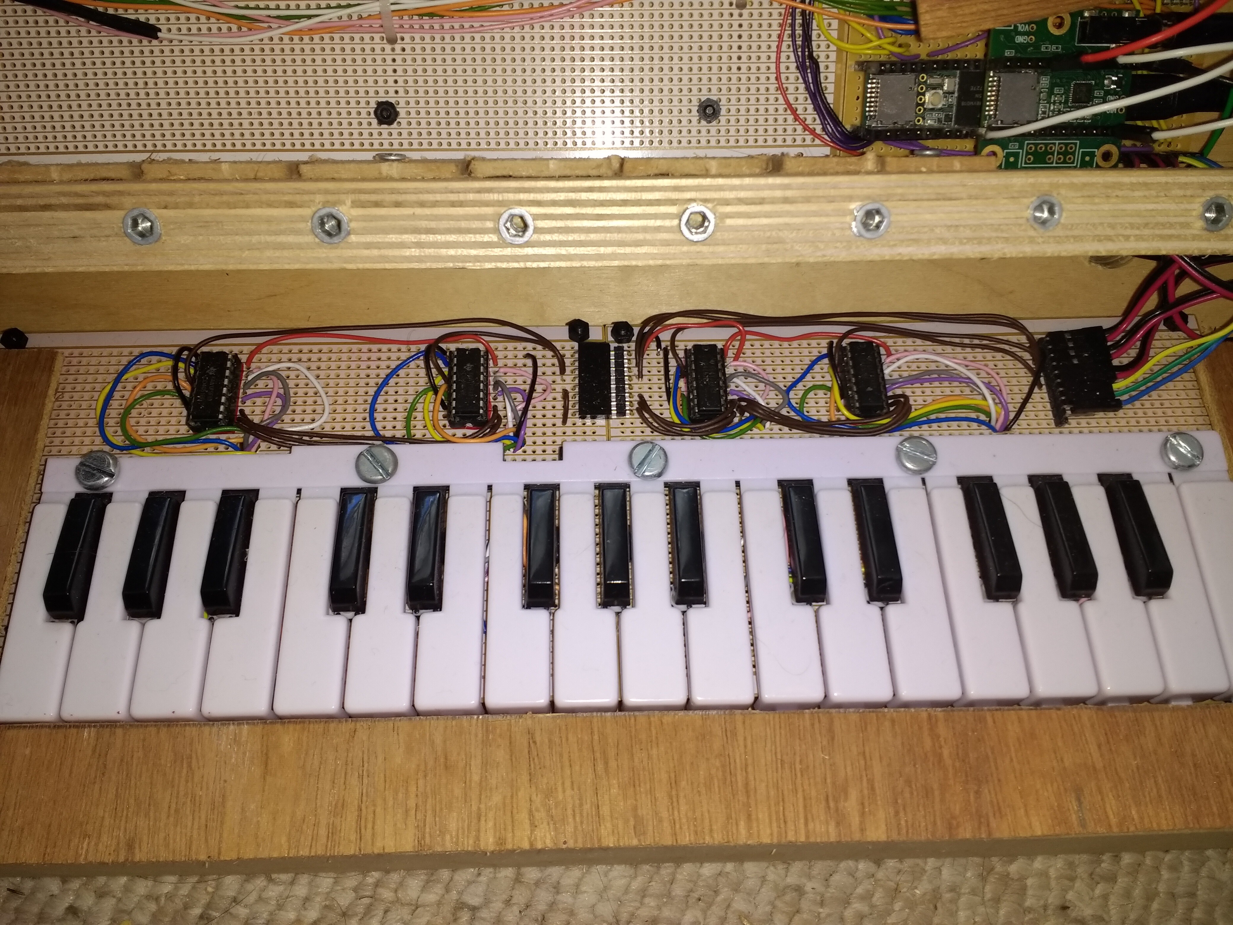
Finally, here's a look at how the keyboard mechanism works. Again, it's a bunch of multiplexer chips (I promise I do sometimes use other chips, this project just happened to need loads of the same one!). There is a tactile button under each key, and the keys themselves were borrowed from an old toy keyboard and secured with machine screws.
Discussions
Become a Hackaday.io Member
Create an account to leave a comment. Already have an account? Log In.