 MakersBox
Electronics can be frustrating with successes few and far between. I’ve come to believe that the “Keep it Simple” philosophy is key, especially for beginners. Purposely limiting the circuit size and scope can greatly simplify development as each bite size portion of a larger project can be designed, debugged, and programmed independently.
This is really the Arduino + Shield system, only smaller. An Arduino shield sized PCB is a bit expensive for iterating prototypes whereas one square inch is only $5 for three copies at OSH Park! Most sensors work off I2C or SPI, and with a couple extra data and analog pins, we can cover a large number of uses with just a few pins. Here is what I’m thinking for the basis of microcontroller development board:
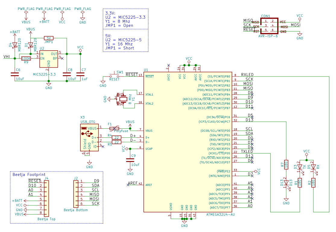
- USB ready (without FTDI!), so maybe 32U4 to start, SAM21 latter.
- 3.3V for compatibility with sensors and low-power use.
- 0.1” Pitch headers for breadboarding (and ability to route between pins).
- Surface mount components capable of hand assembly (i.e. 0603 or larger, packages with leads where possible).
- I2C and SPI pins.
- Additional data (PWM please) and analog pins as will fit in the format.
Yes, commenters who didn’t read this far, there are already some very well designed dev boards that meet these requirements. Adafruit’s IstyBitsy and Sparkfun’s Pro Micro are two well executed examples. And they are open source with Eagle files available, albeit without details about components typically found in bill of materials (BOM). And while both companies provide excellent breakout boards with example software, they still need to be breadboarded or jumpered in to use. Here is what I’m proposing:
- Open Source development board done in KiCad that comes with a full BOM, ready to drop into whatever project you need, either physically or into a schematic/PCB.
- Ecosystem of breakout designs with standardized footprint that can either be physically plugged into the dev board, or the design into the schematic/PCB.
If you are still with me, let’s try a use case: model rocket telemetry. I wanted to update one of my old projects (https://www.instructables.com/id/Radio-Telemetry-for-a-Model-Rocket/) using a dedicated PCB to improve ruggedness. Using the KISS principle, let’s break this into functional blocks (links to project logs as they are built and tested):
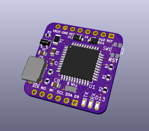
- MCU (Arduino compatible)
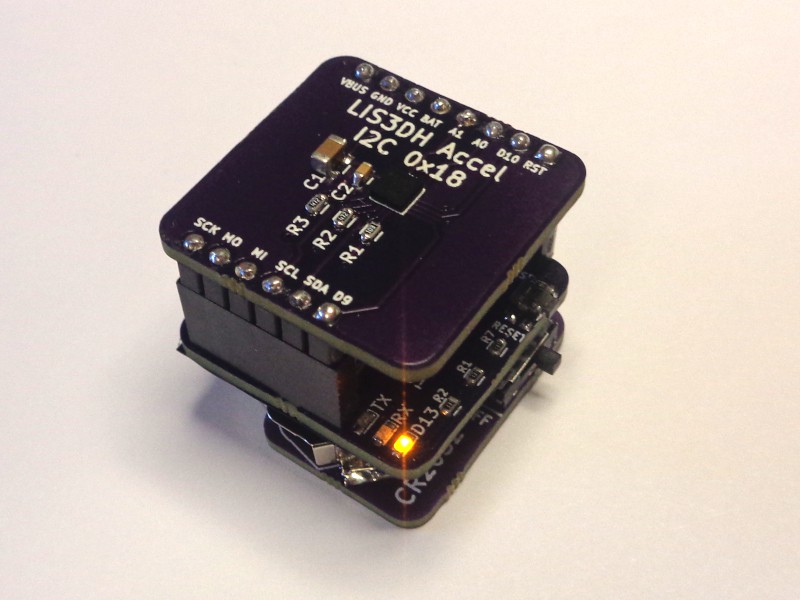
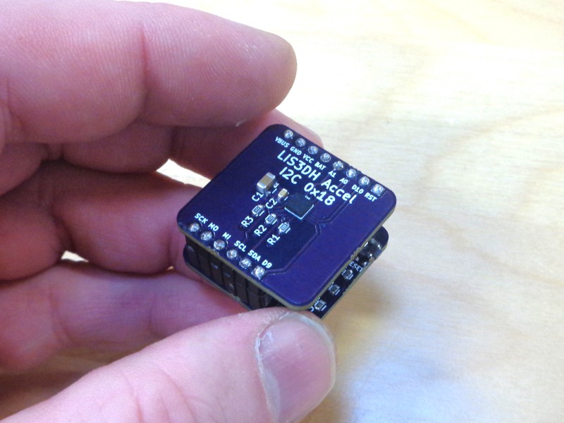
- Acceleration (I2C/SPI)
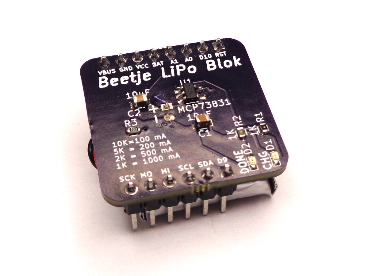
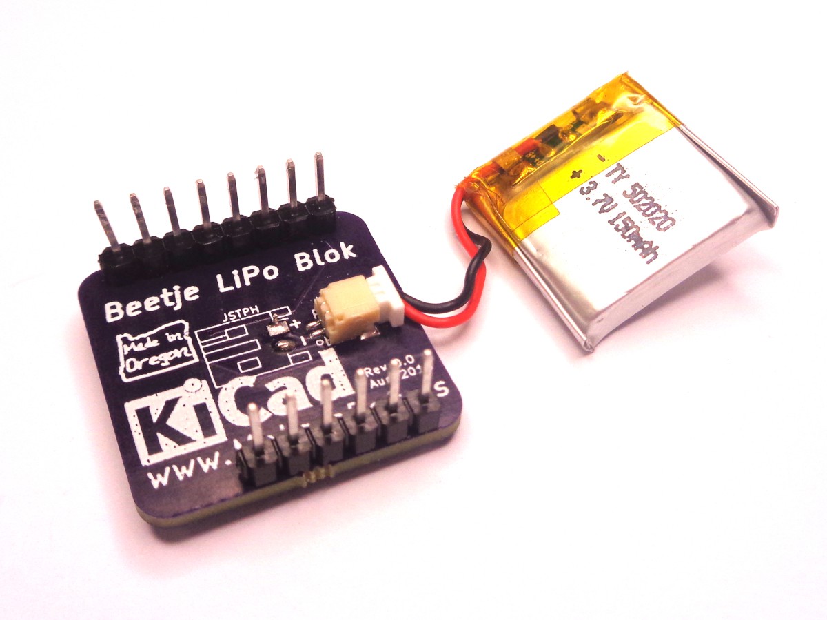
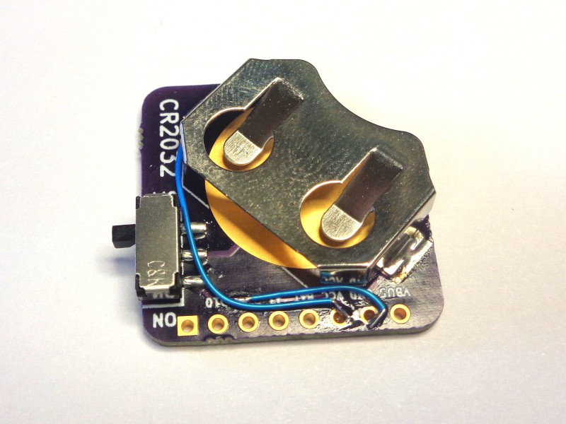
- Power (coin or LiPo)
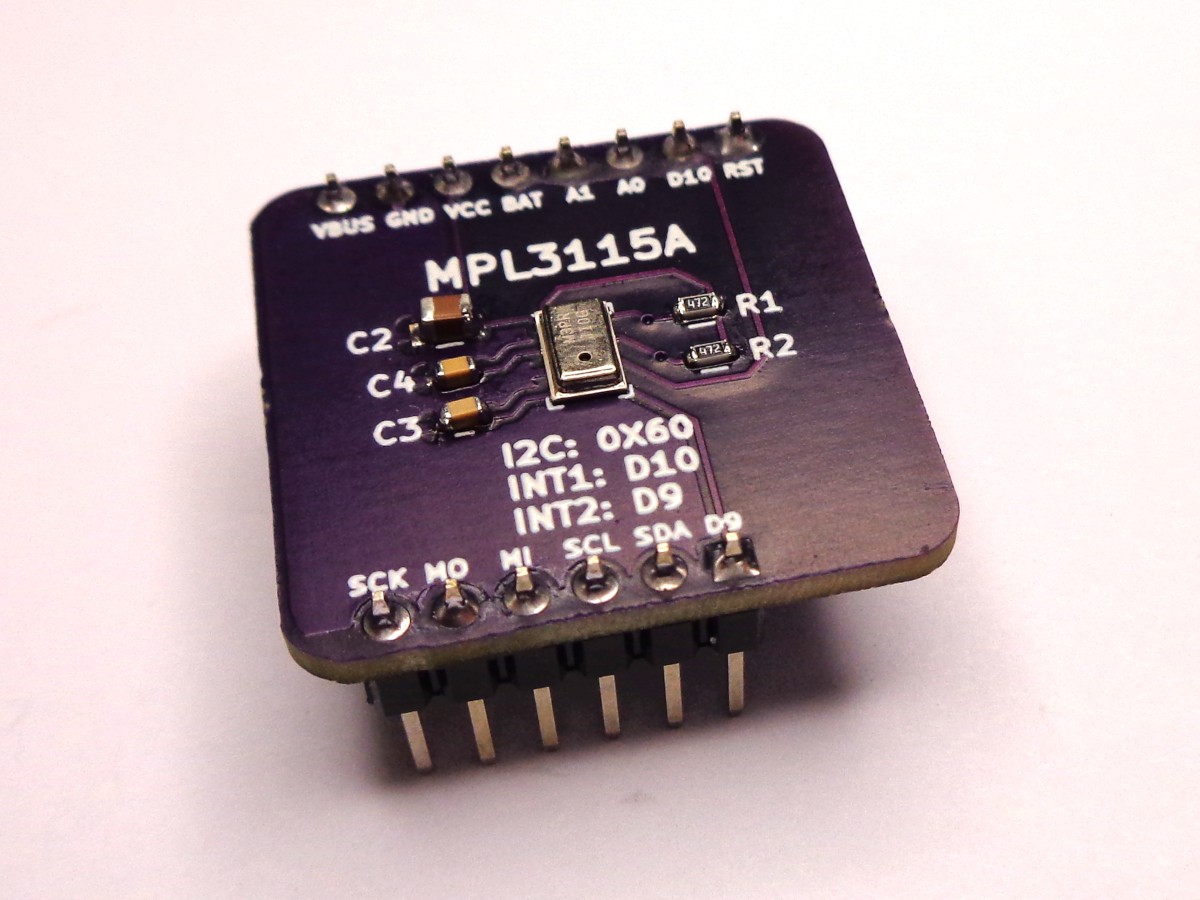
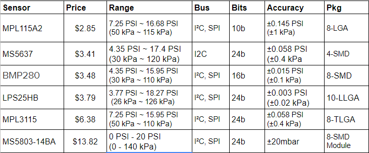
- Pressure (correlates to altitude, I2C/SPI)
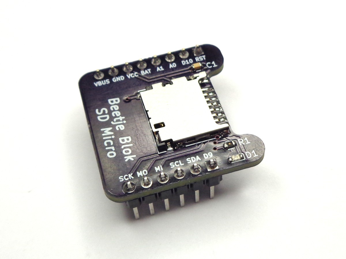
- Data Storage (SD card or EEPROM)
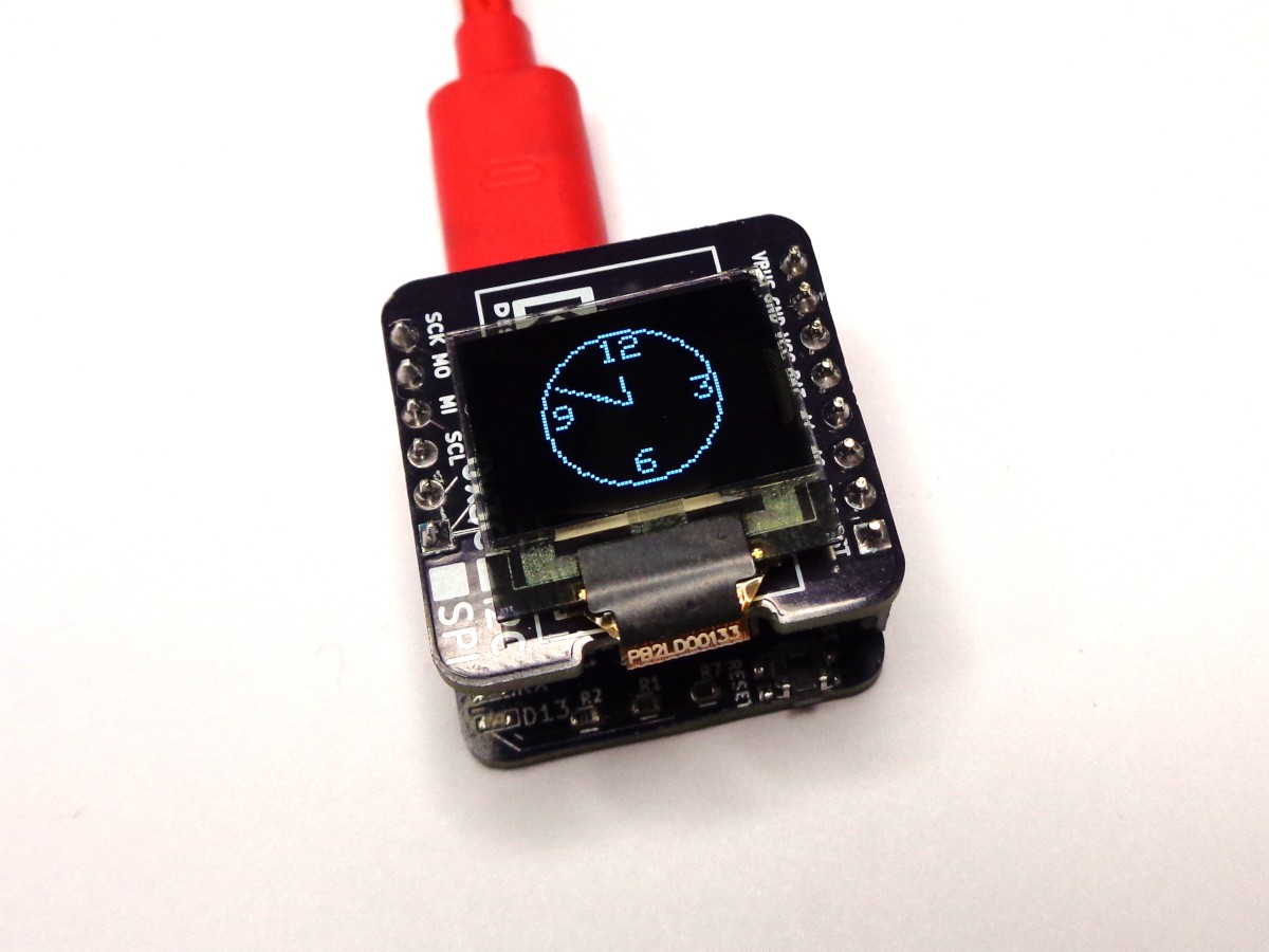
- Display (blink LEDs or OLED I2C/SPI)
Ideally, we’d have a tested block for each piece and could immediately start writing firmware while combining the electrical designs into a single PCB. Or maybe, we’d find a new sensor to try and would need to design and test a block for it.
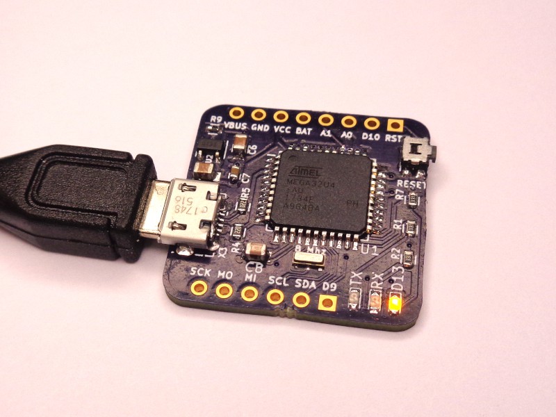
Of course, since we are starting in the real world from ground zero (or near it), let’s start with the MCU block. If I can’t get that working, there is no point in moving forward. And, since Hack-a-day is running another One Square Inch contest, let’s use that as the basis of the footprint. We are going to build things bit-by-bit. Since I sell a disproportionate number of kits to the Netherlands, I’m going to call these "Beetje Bloks", which translates from Dutch to “bit blocks”. I’m not sure how to pronounce it. Let’s say it “Beet-Cha”, as in, “I betcha can’t design a one-inch square dev board”.
Current files on Github: https://github.com/aspro648/Beetje-Bloks

 doctek
 Justin
 Jon Kunkee
 Jeff Cooper