 Cedric Anné
WARNING: Don't try this at home.
0%
0%
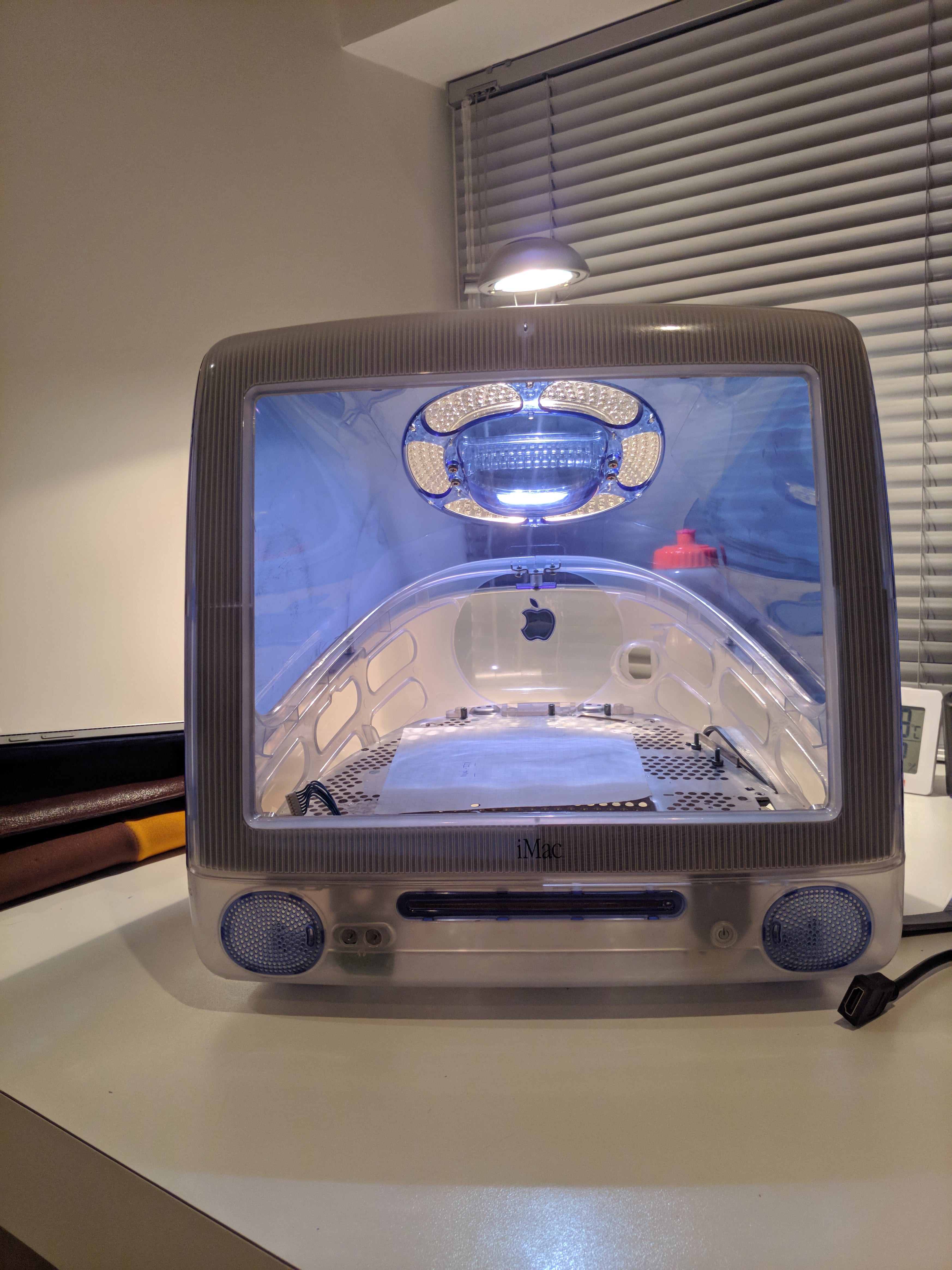
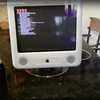
iMac G3 Casemod
Building a gaming pc in an old iMac G3 case
Become a Hackaday.io member
Already have an account? Log in.
Just one more thing
To make the experience fit your profile, pick a username and tell us what interests you.
Pick an awesome username
hackaday.io/
Your profile's URL: hackaday.io/username. Max 25 alphanumeric characters.
Pick a few interests
Projects that share your interests
People that share your interests
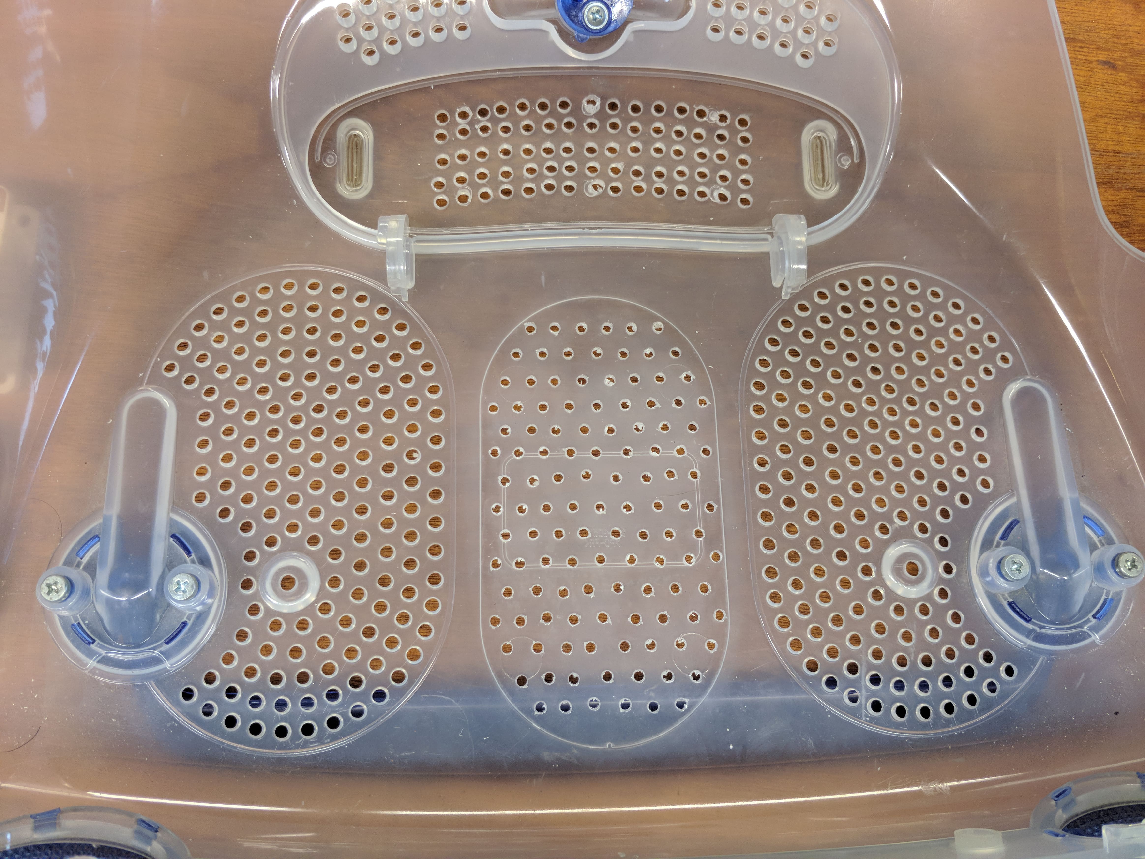
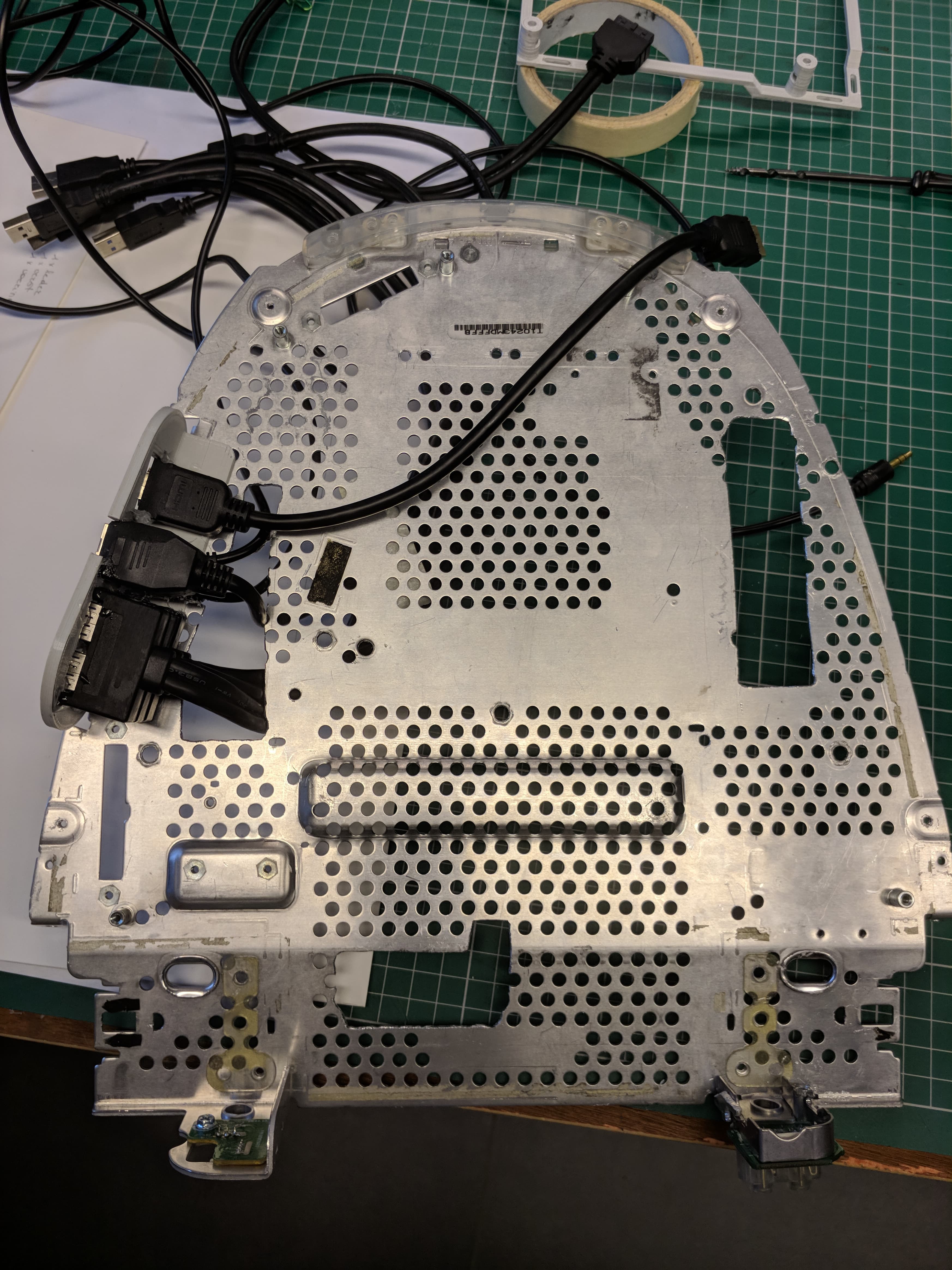
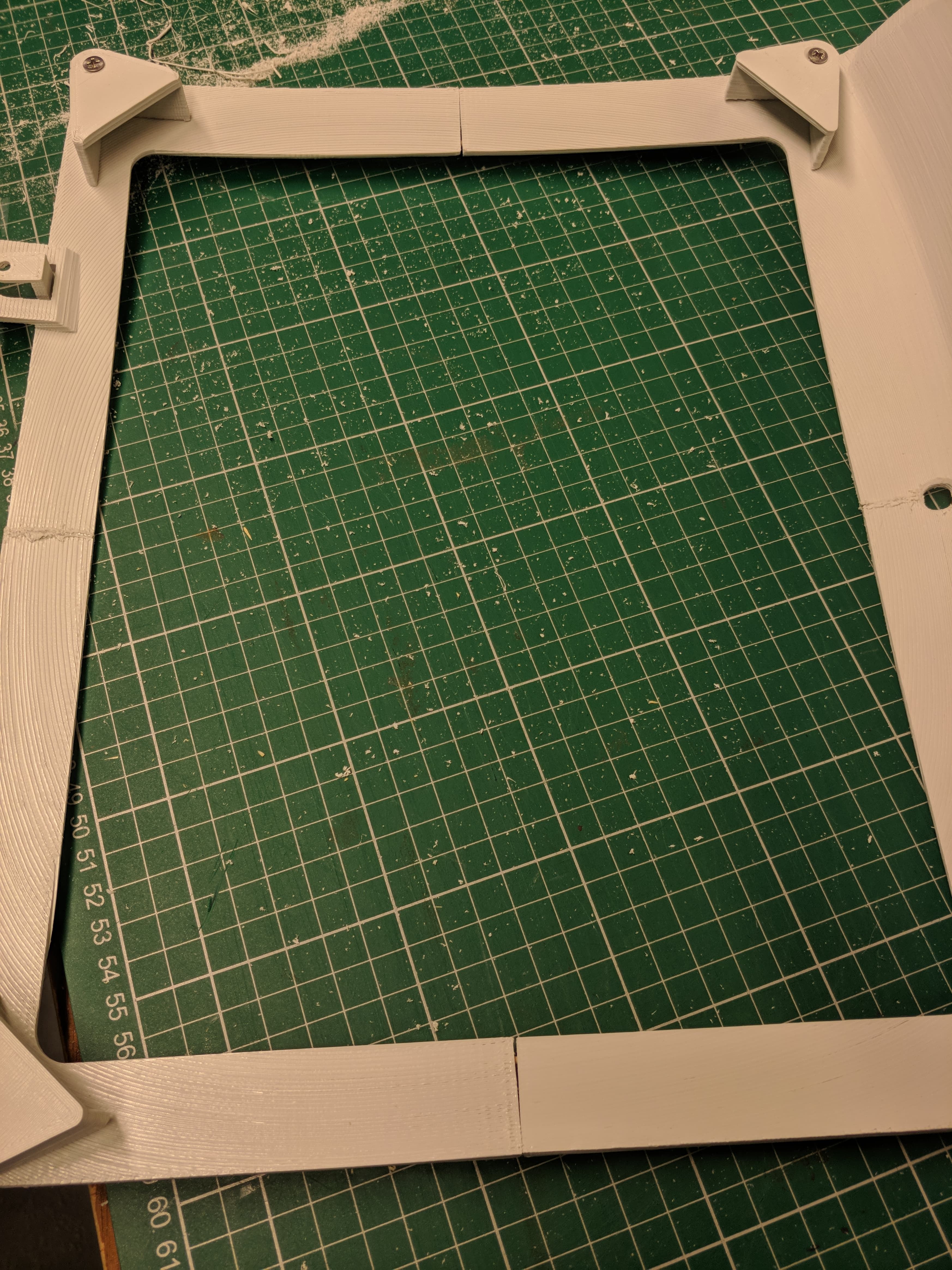
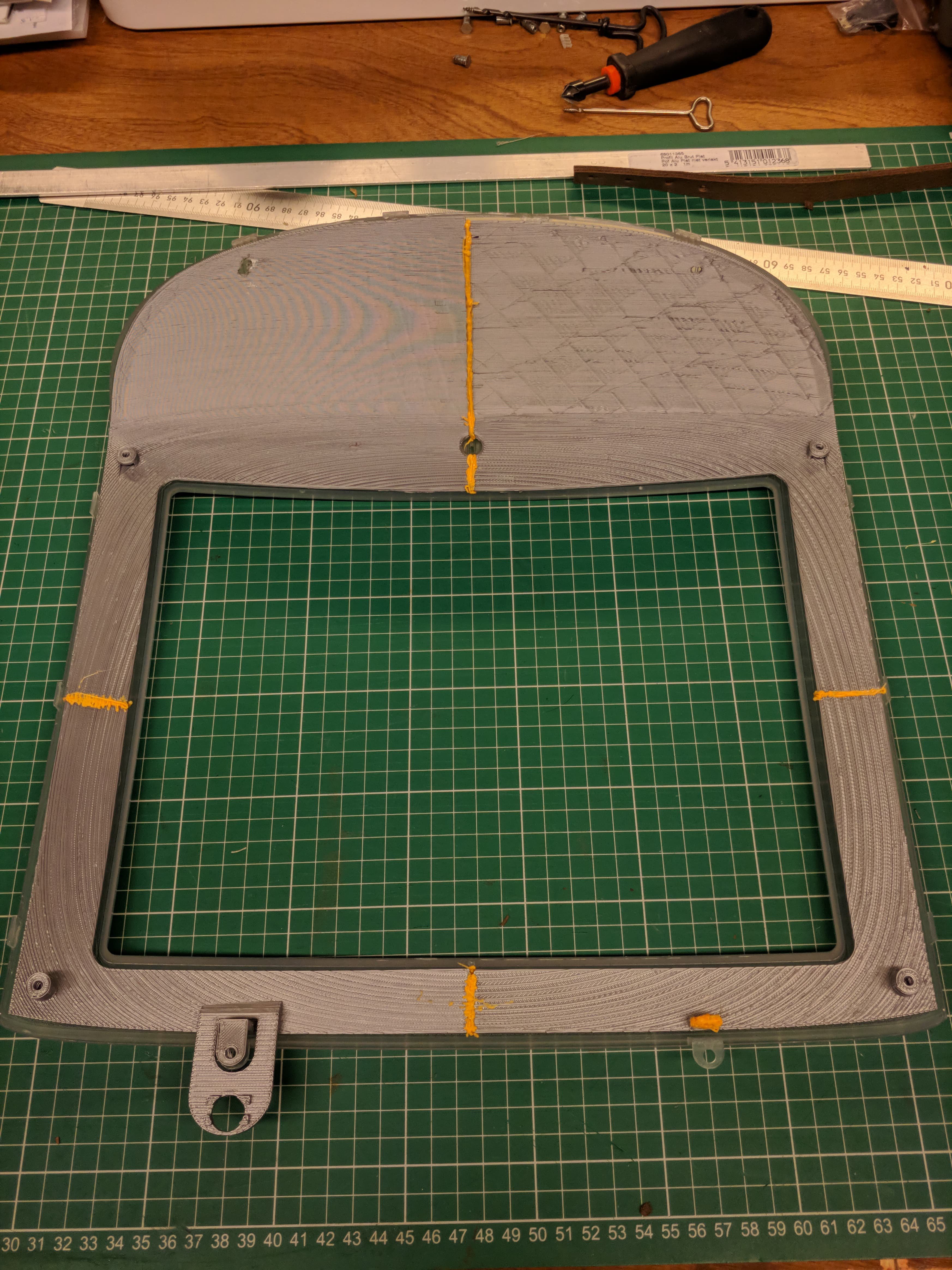
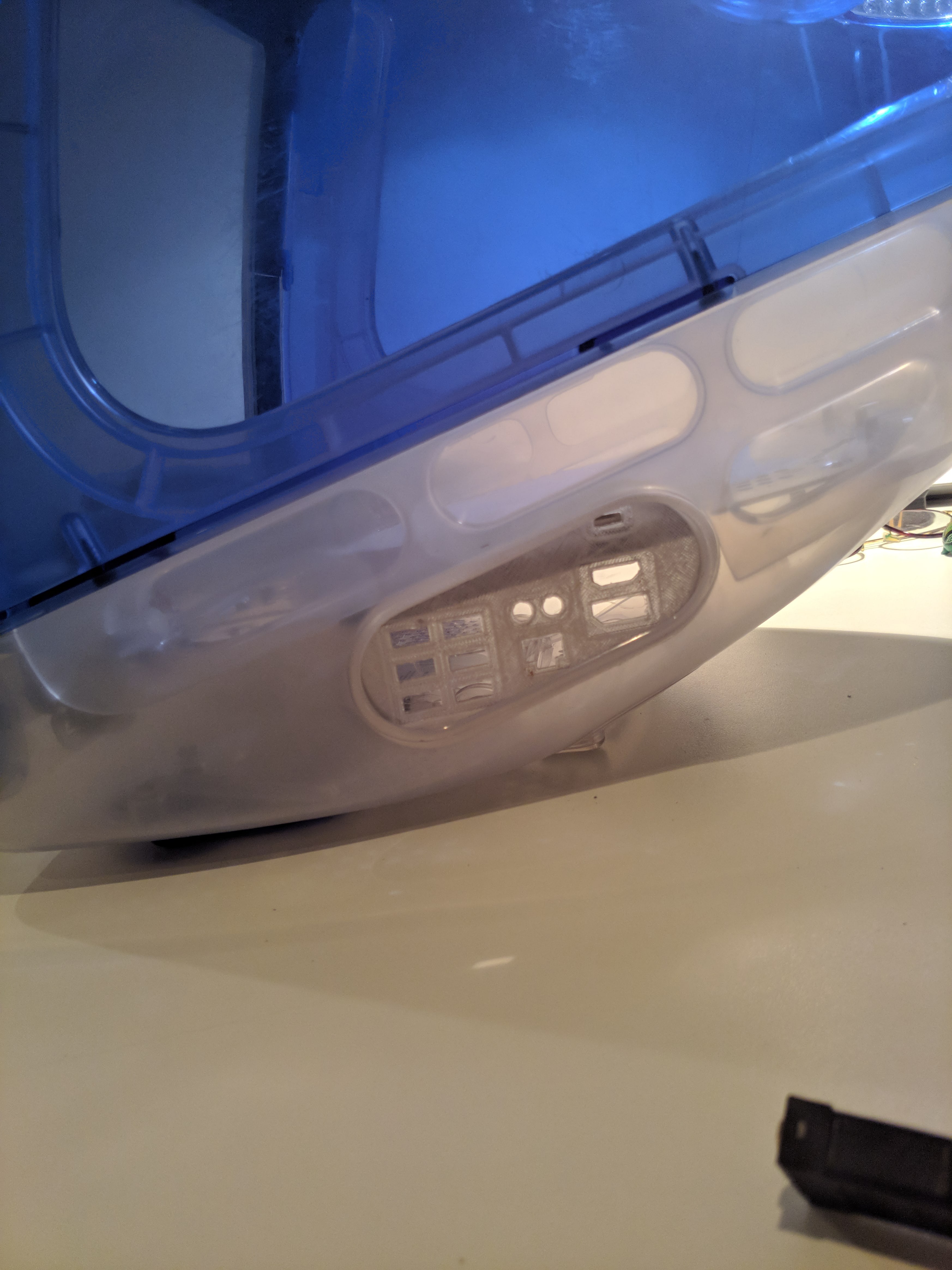
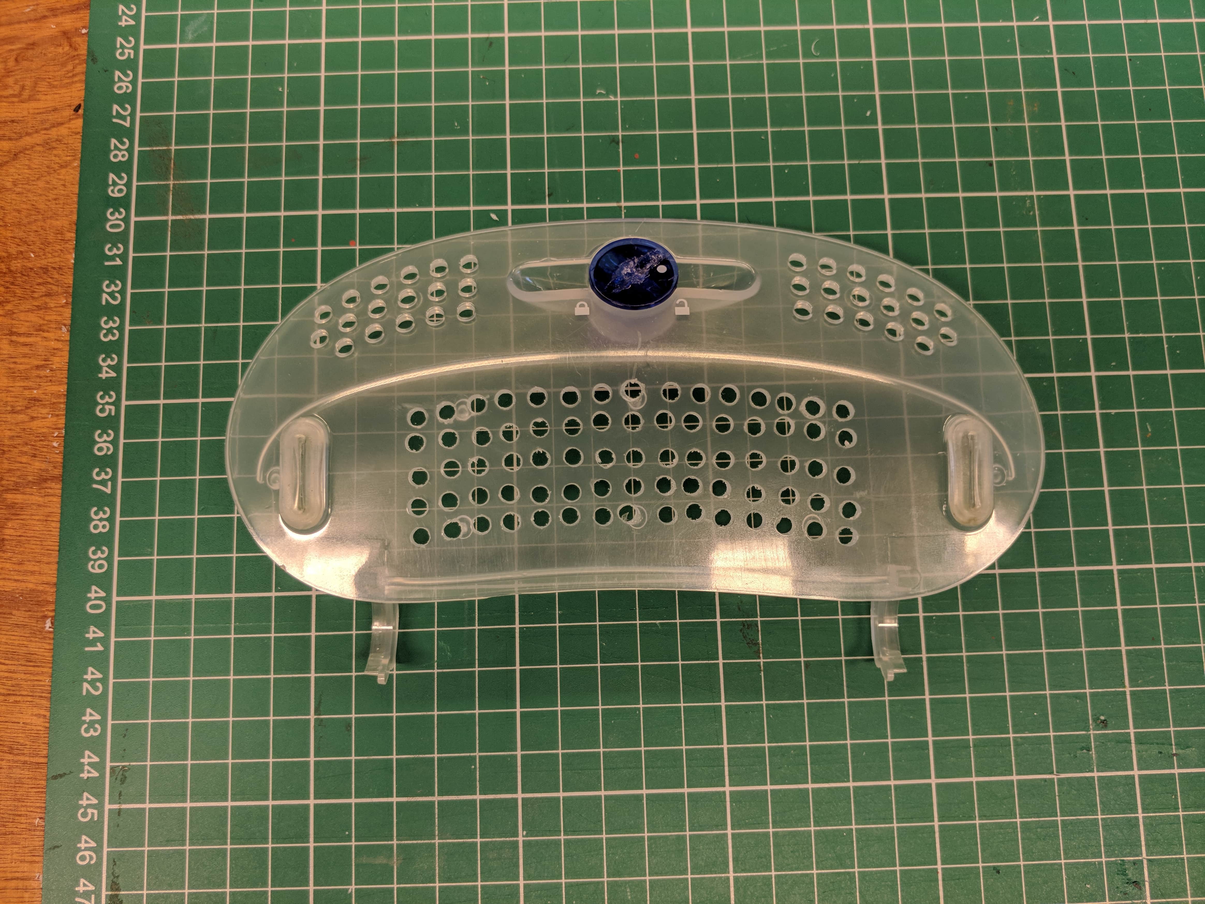
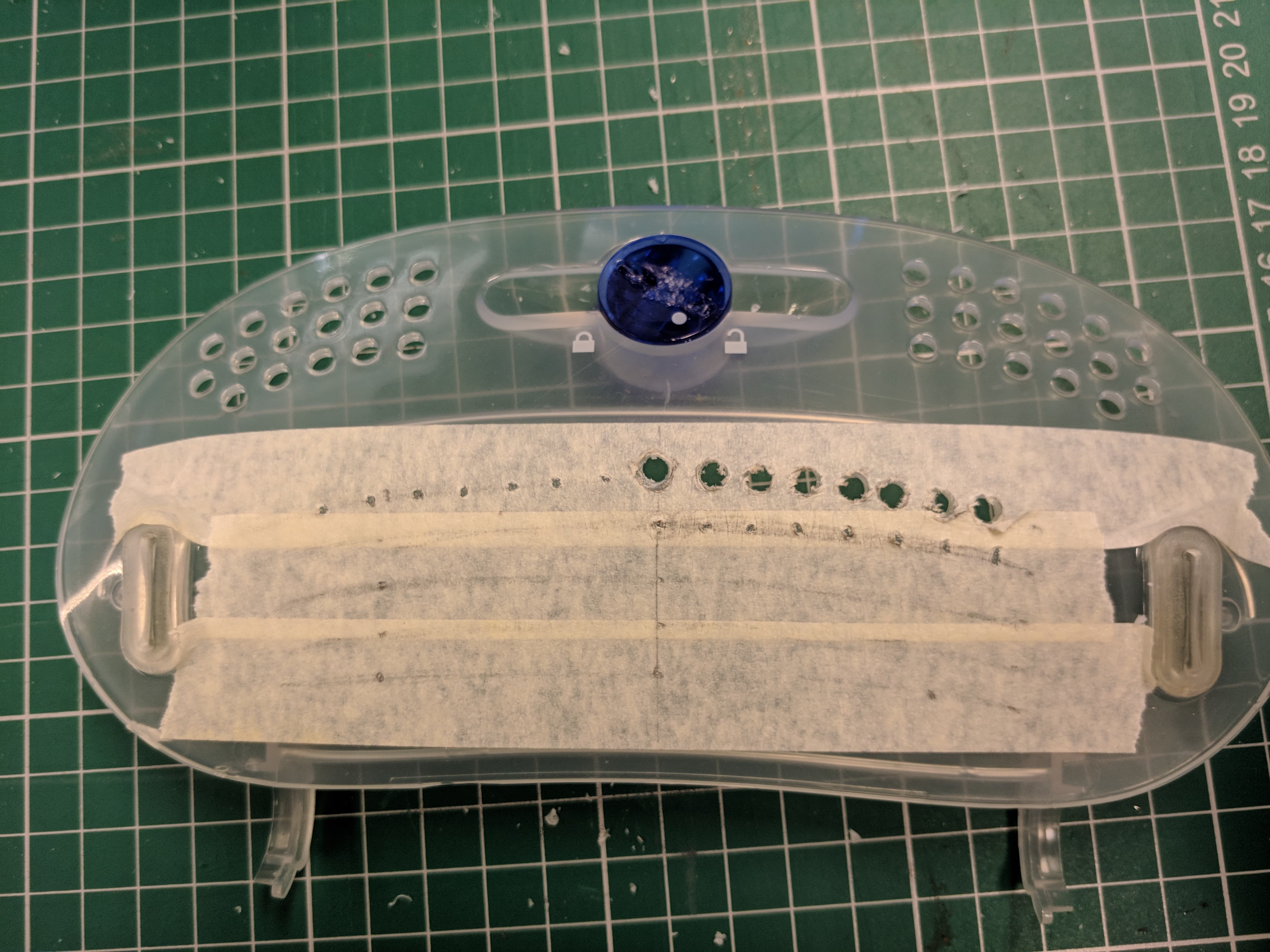
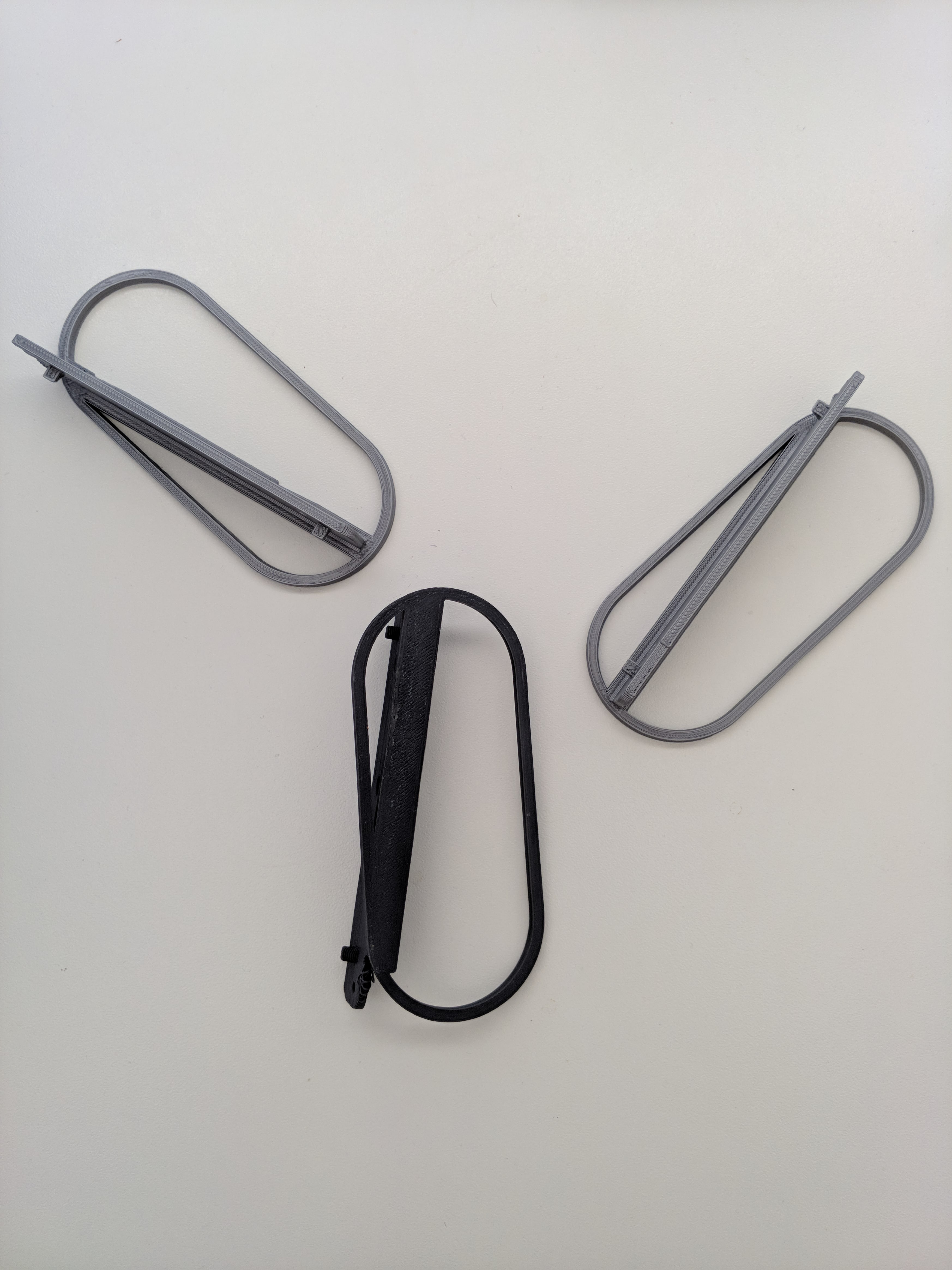
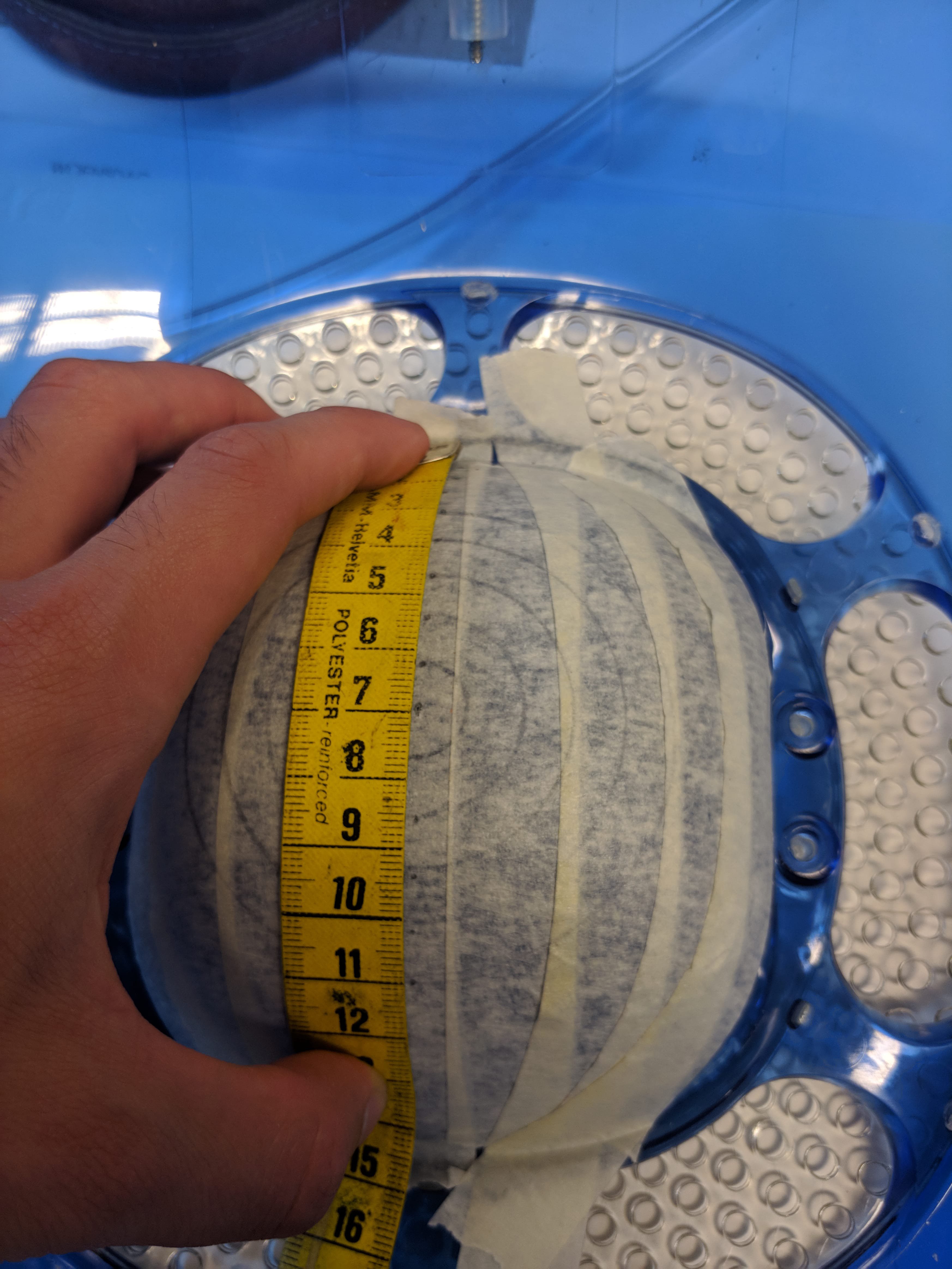 I tried measuring by hand, but that turned out to be a hasstle, so I made a template (like one on those strands of people holding hands you make as a kid) that would show me where to drill holes in a hexagonal pattern.
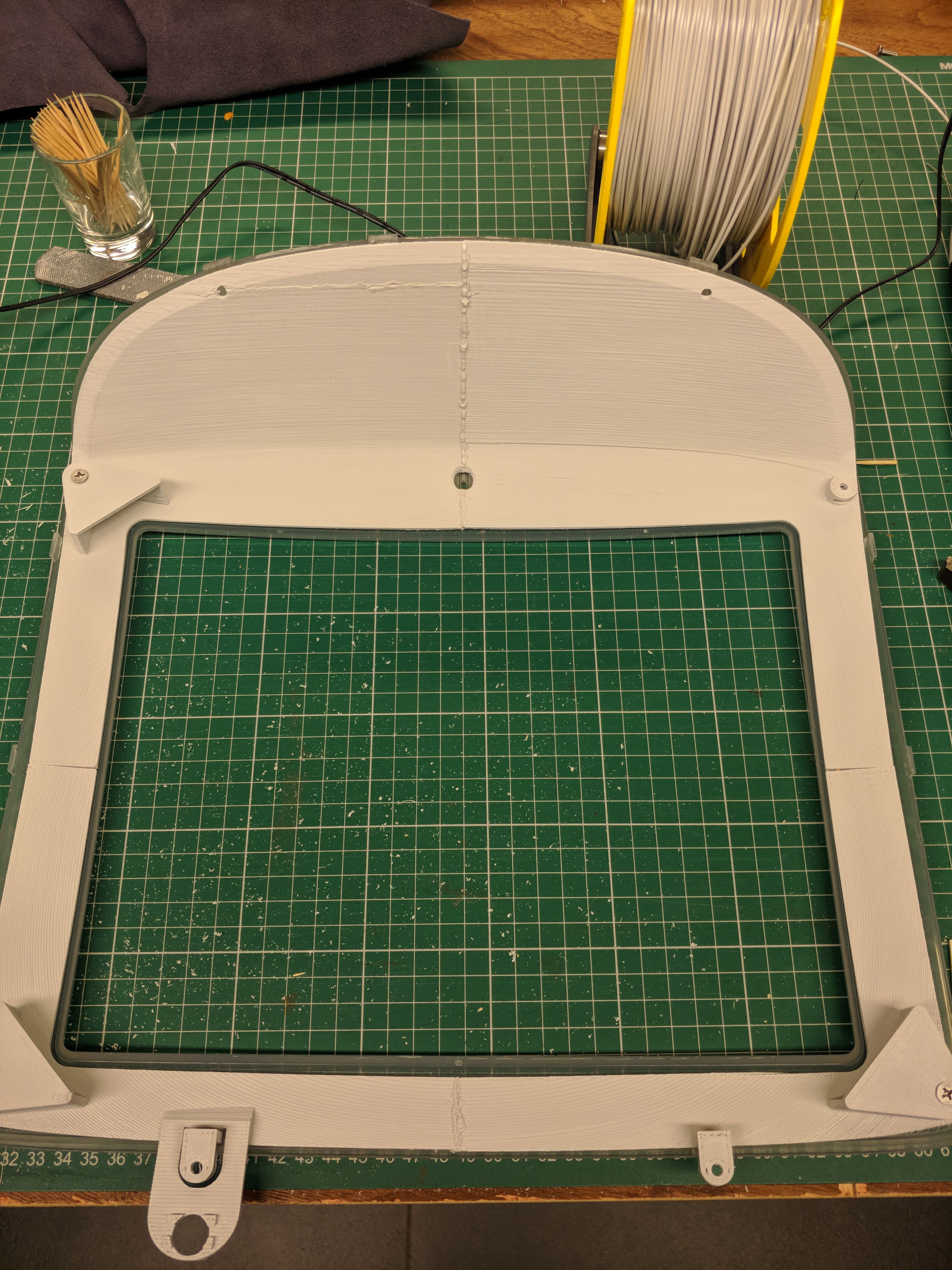
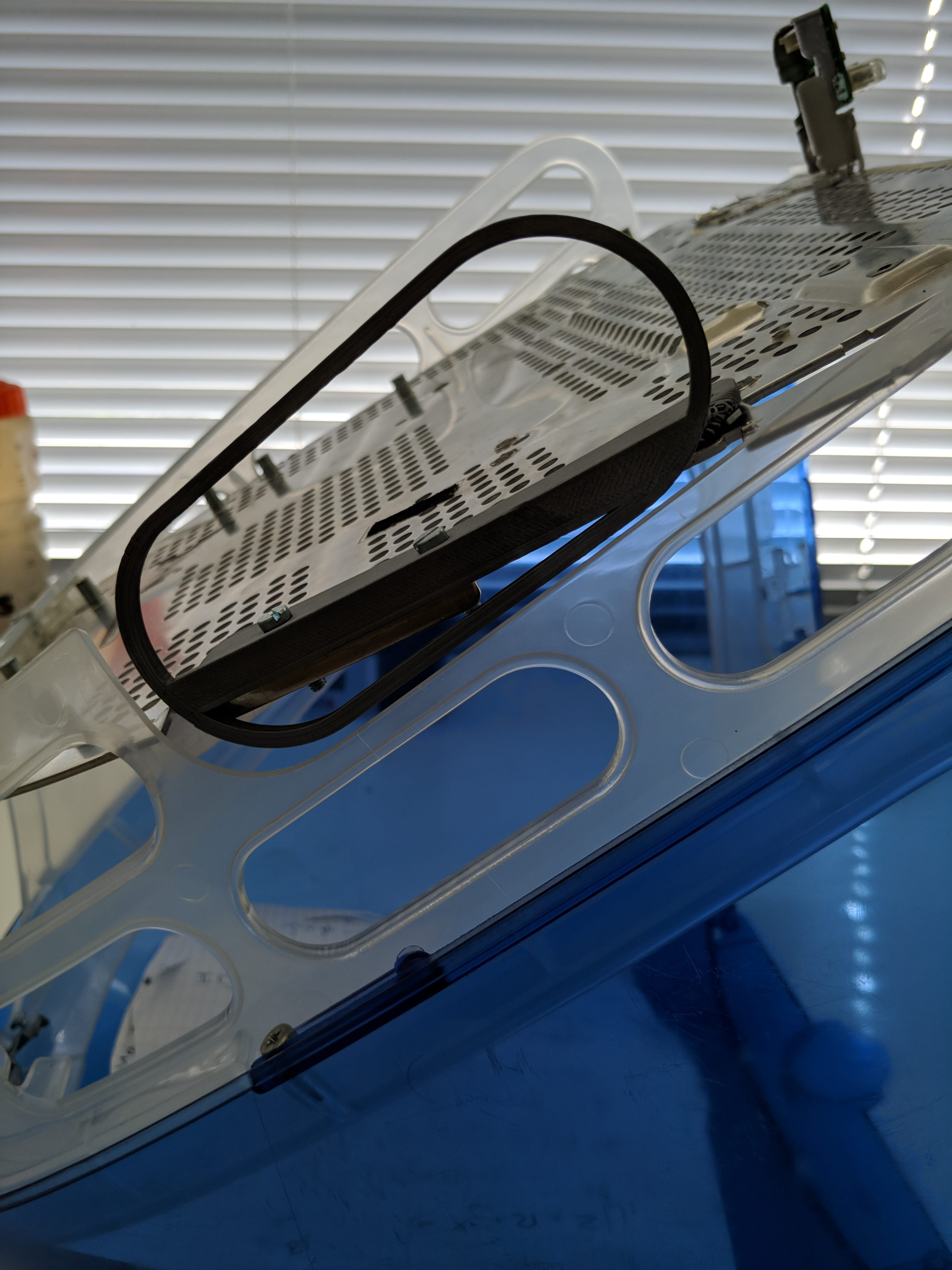
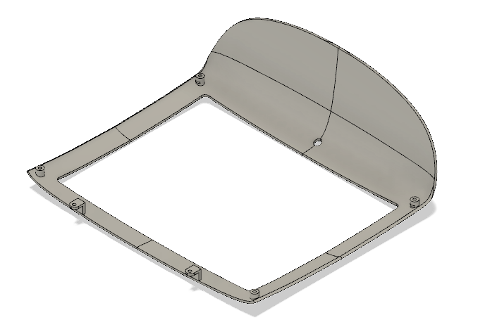
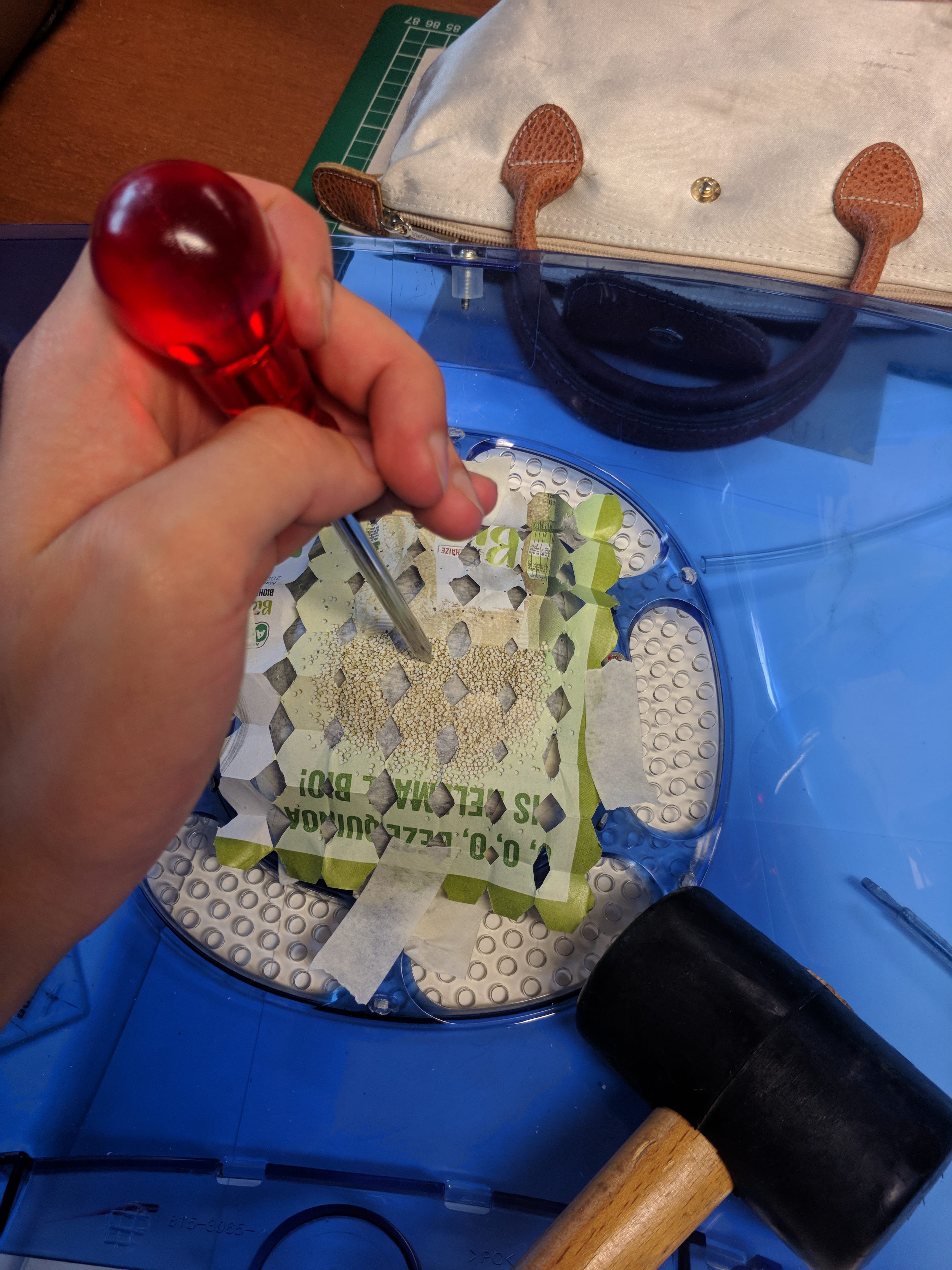 The finished product should look something like this (this is with the arms for the 200mm fan attached).
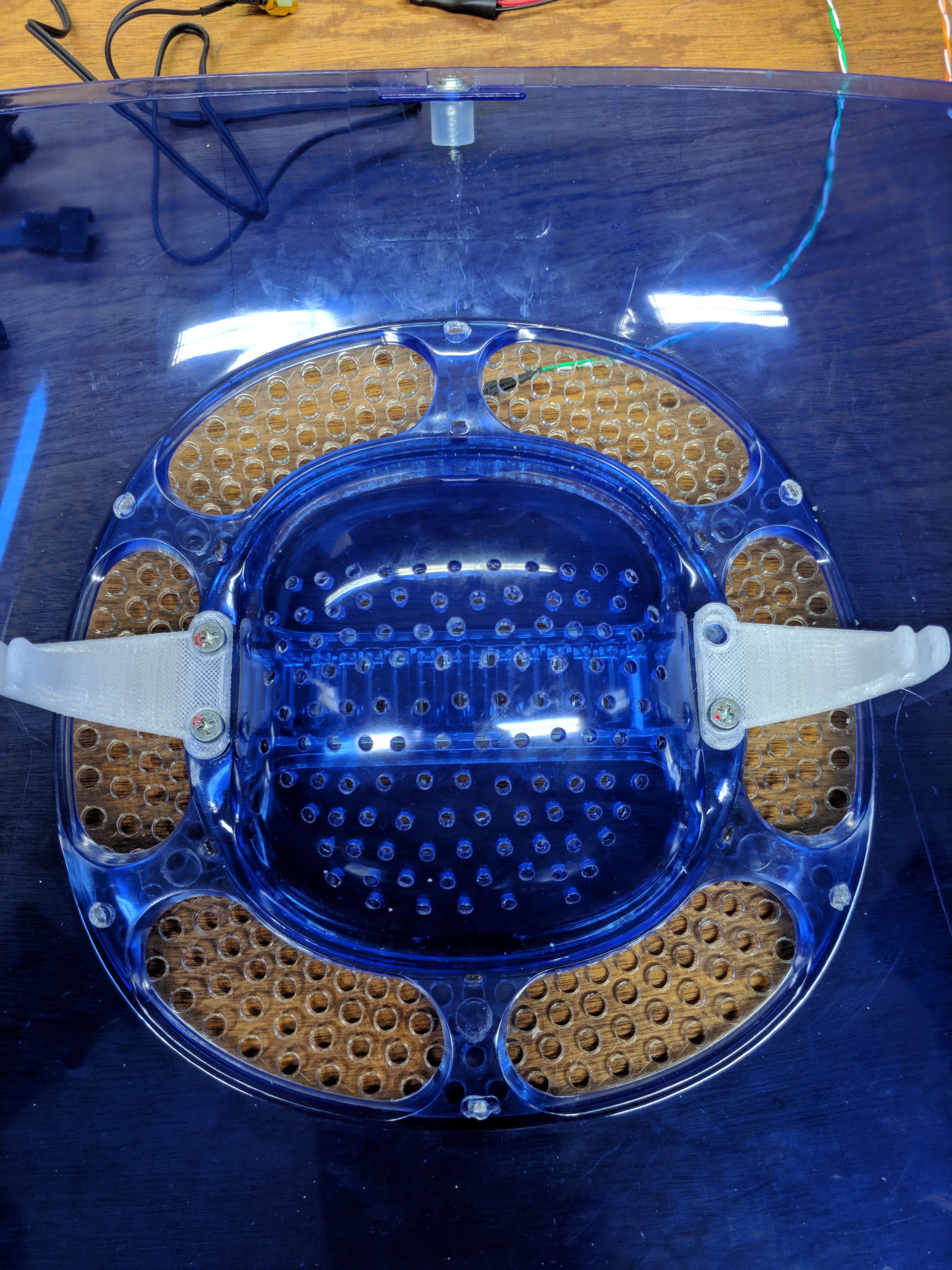
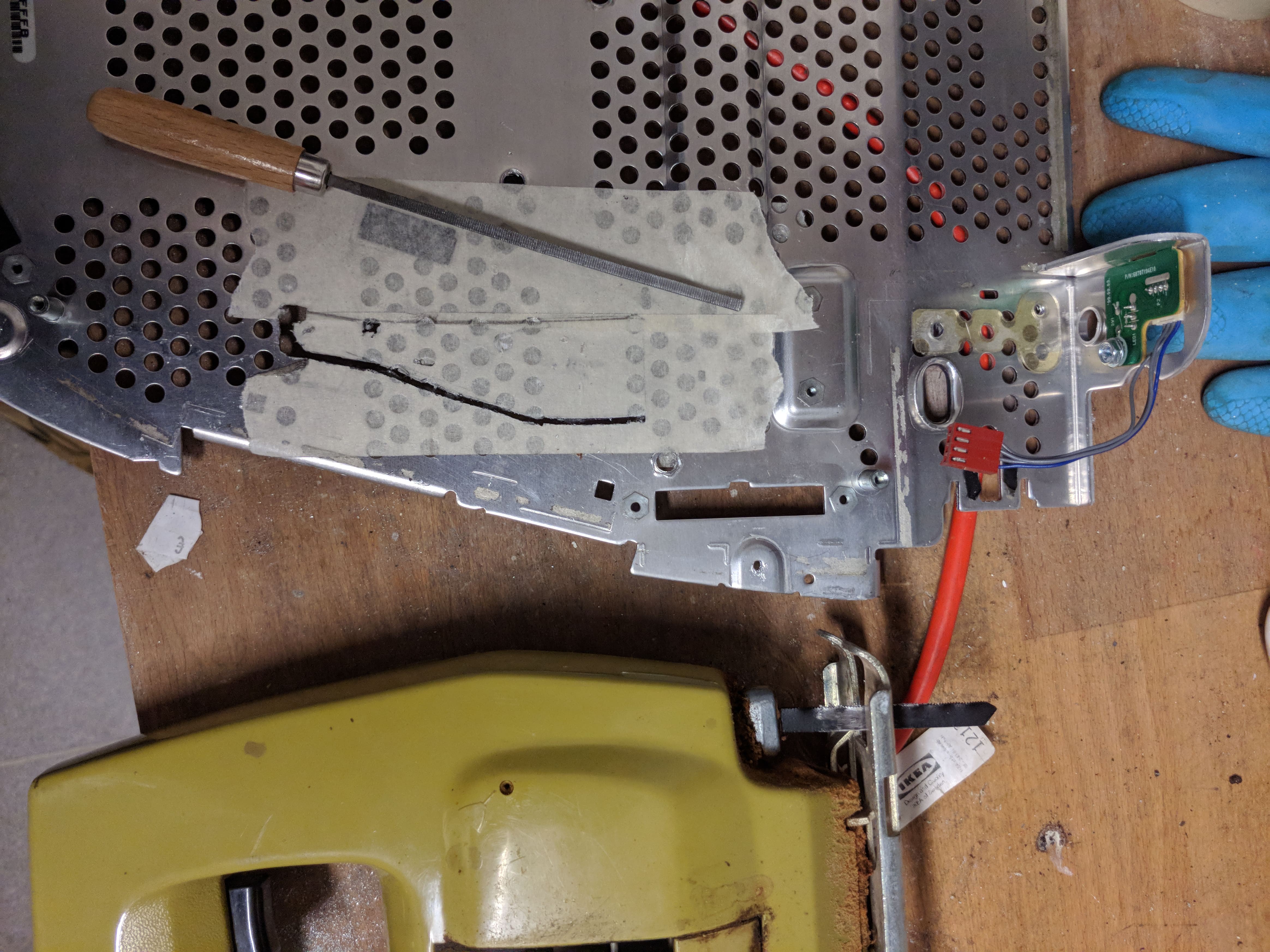
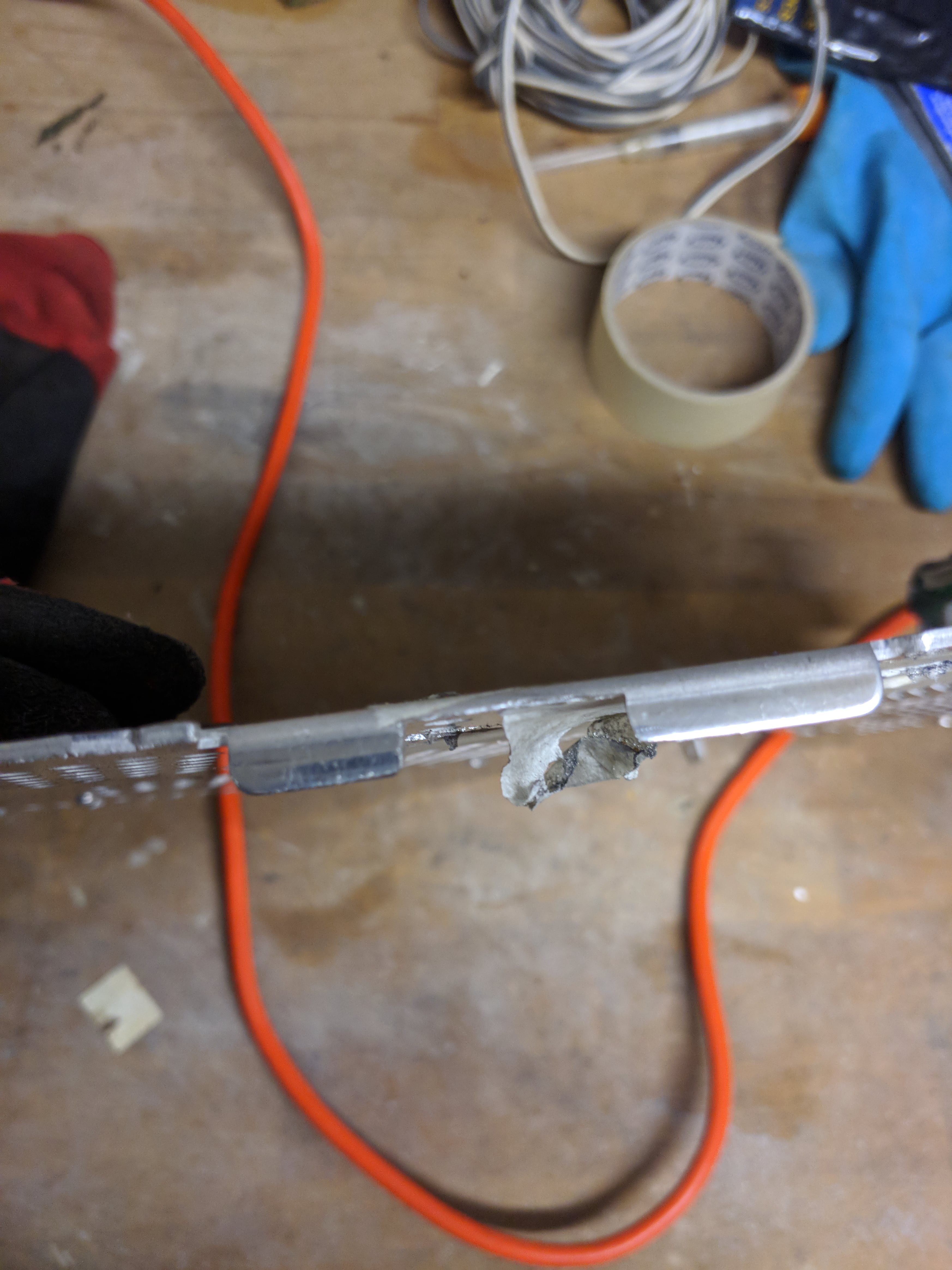
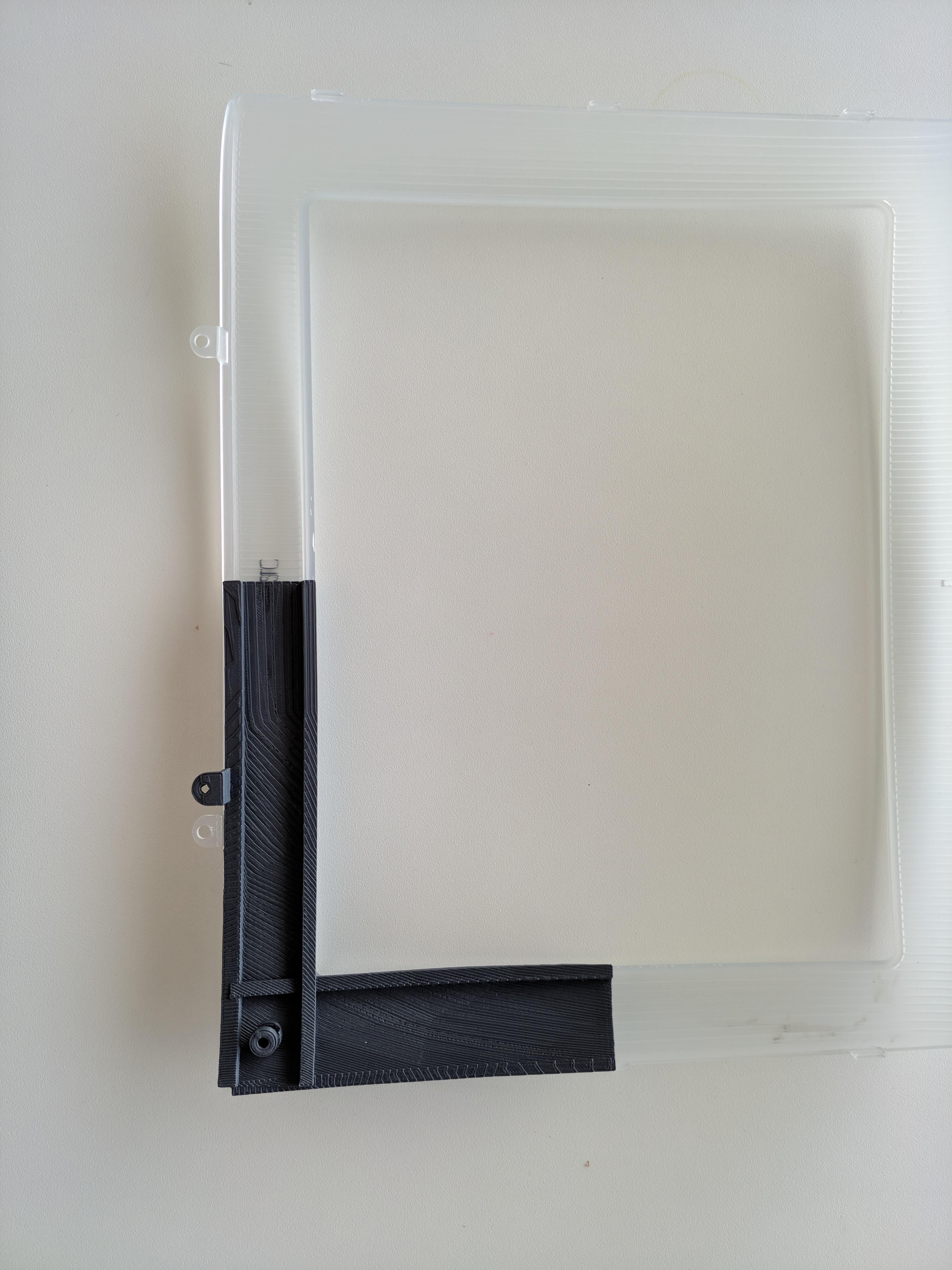
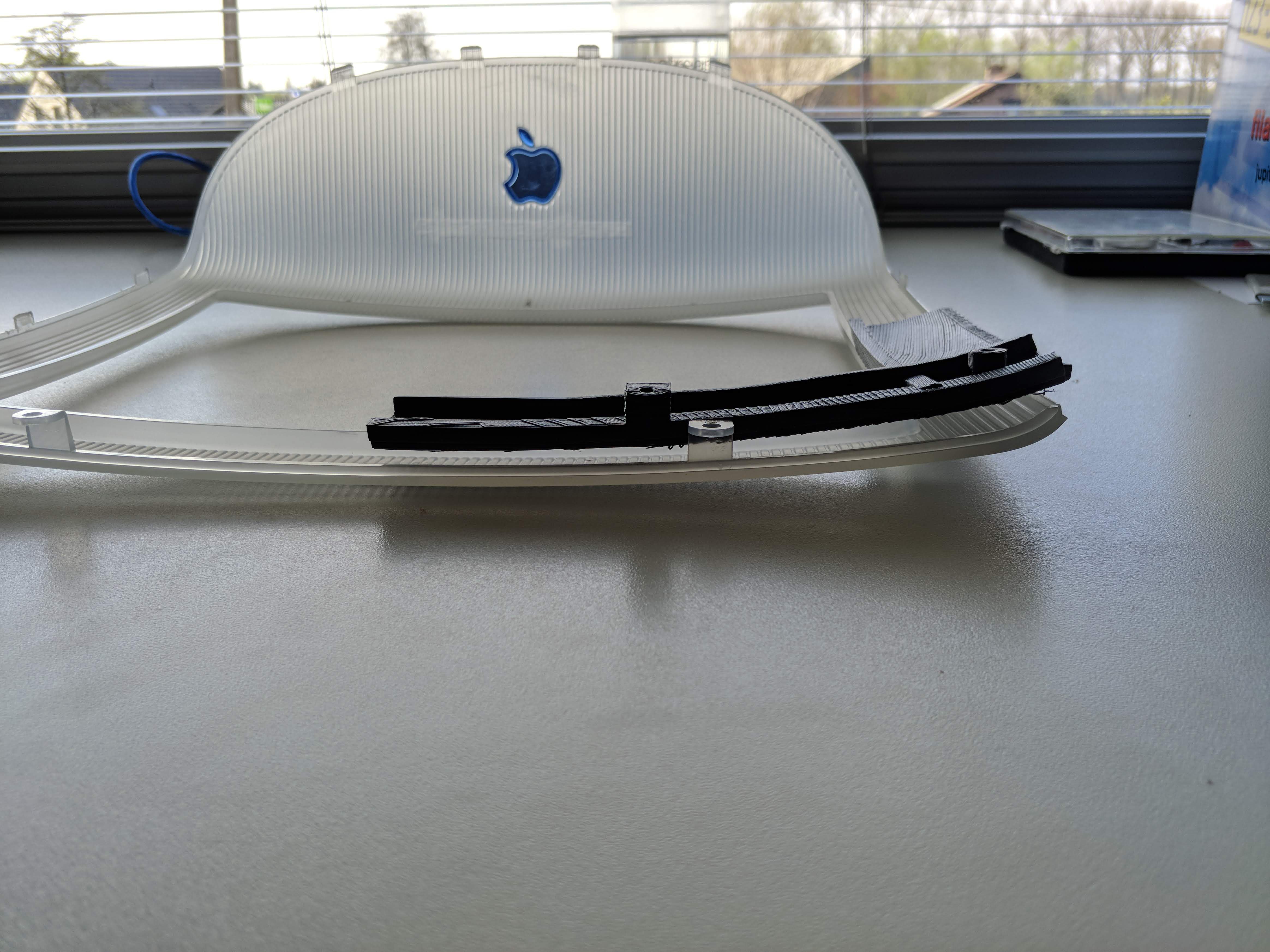
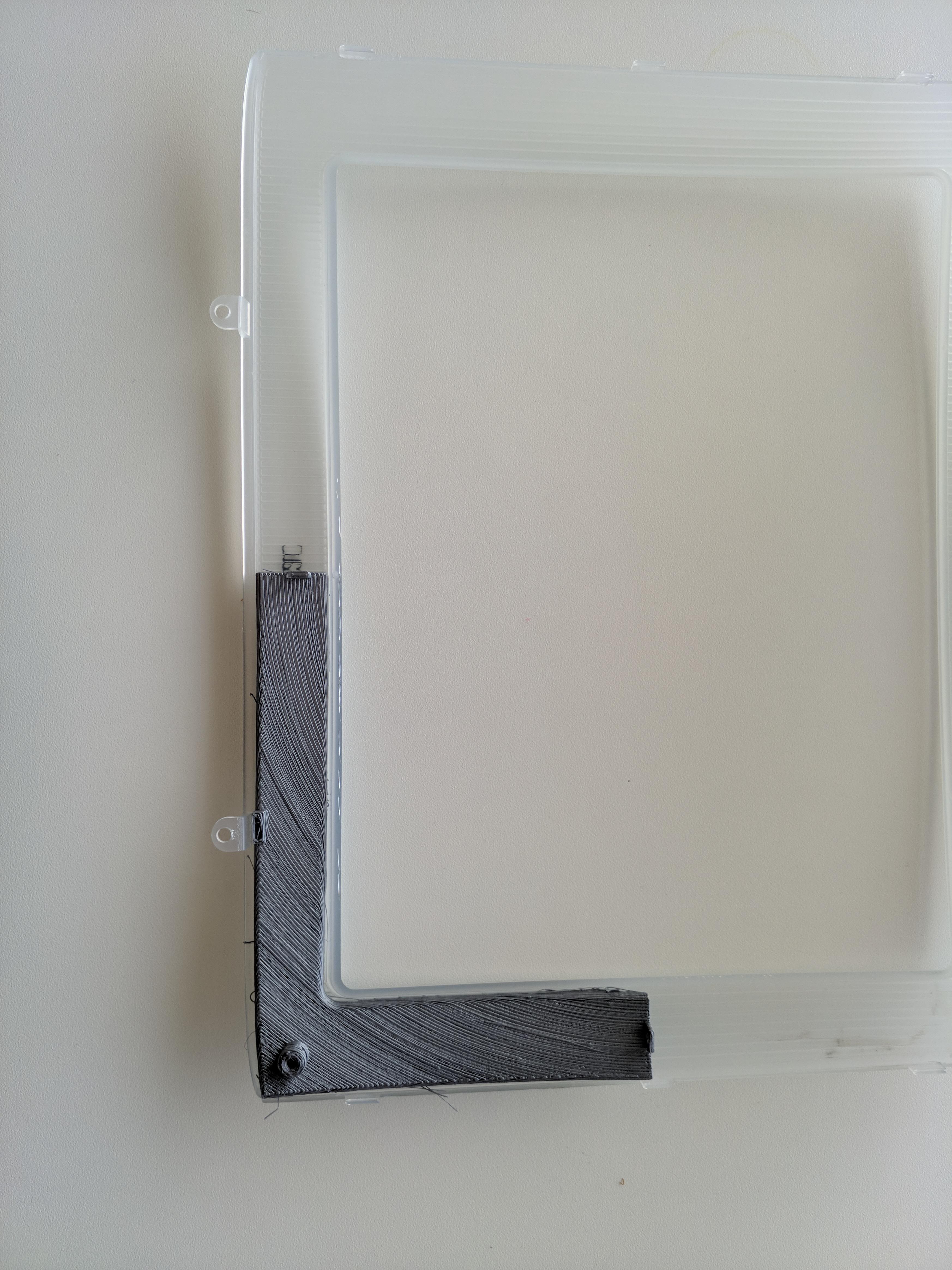
 The front (directed towards the back of the iMac) wasn't that bad. The back however...
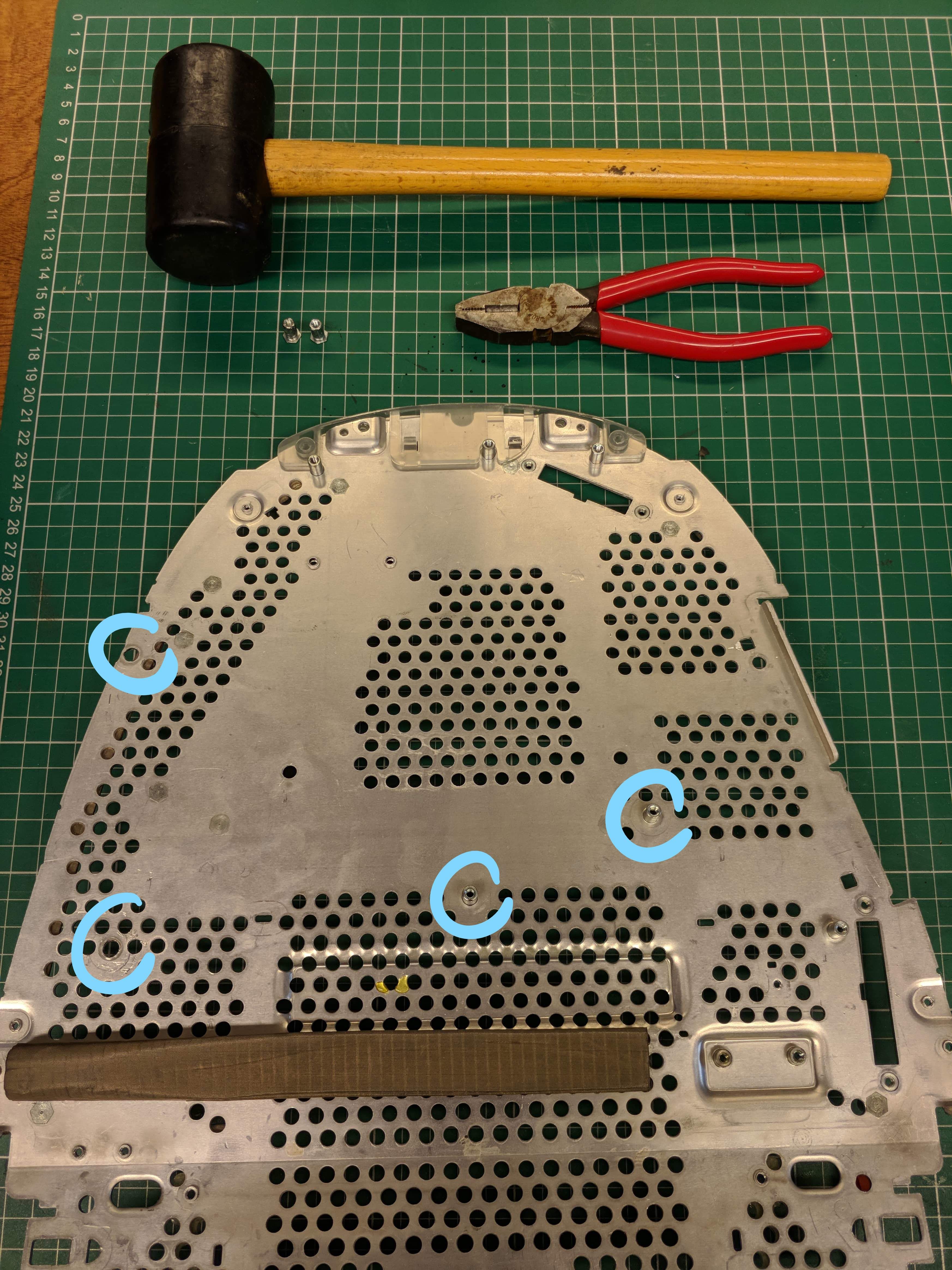
 As you can see I used metal brackets on this one instead of 3d printed angles. That's because the PETG I was printing in kept breaking on that spot and this was on day 4 and I got tired of waiting for the printer. I might update the model (this is also a model with a part cut off and holes drilled into it)... or I might not... We'll see :P
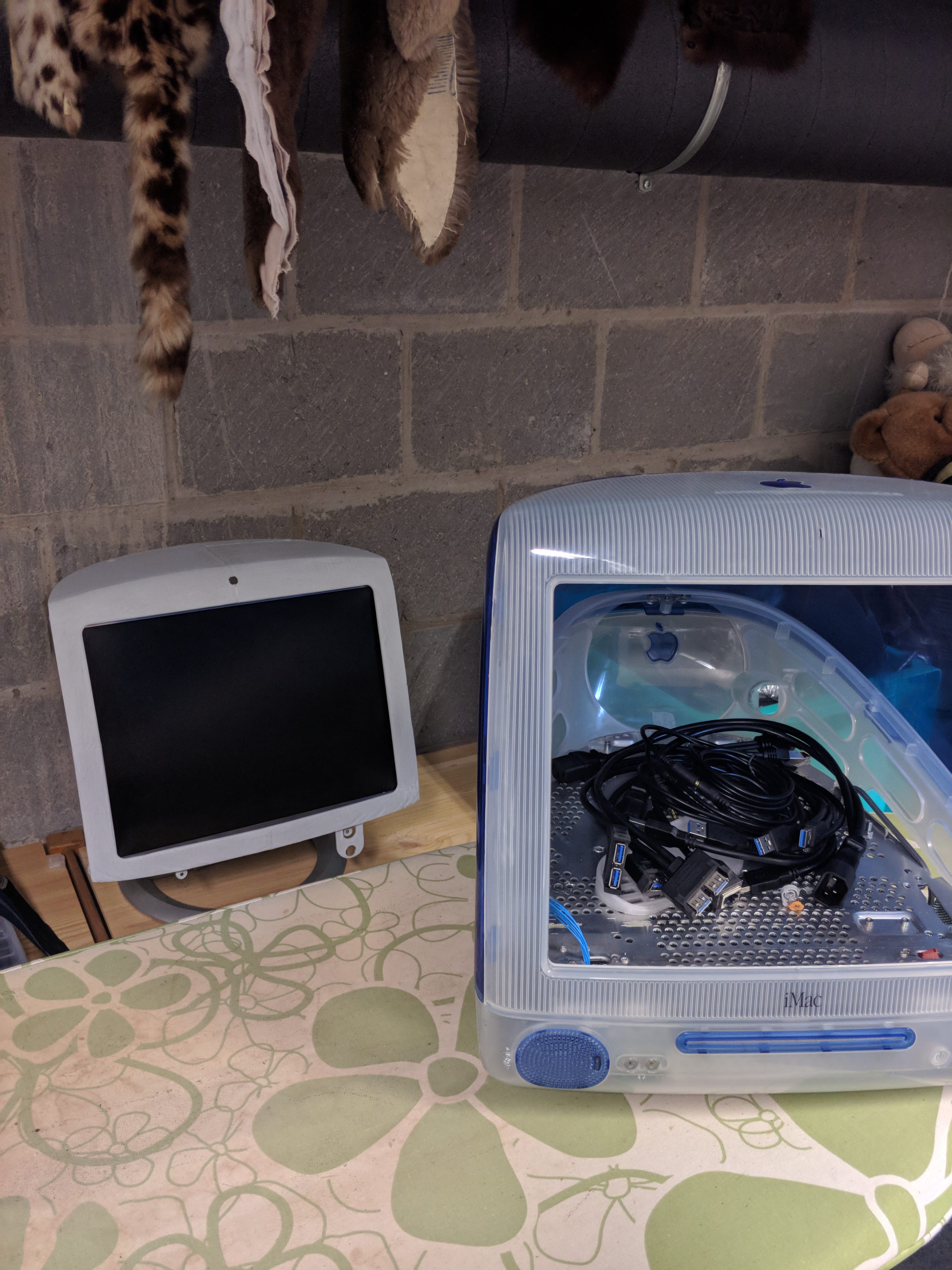
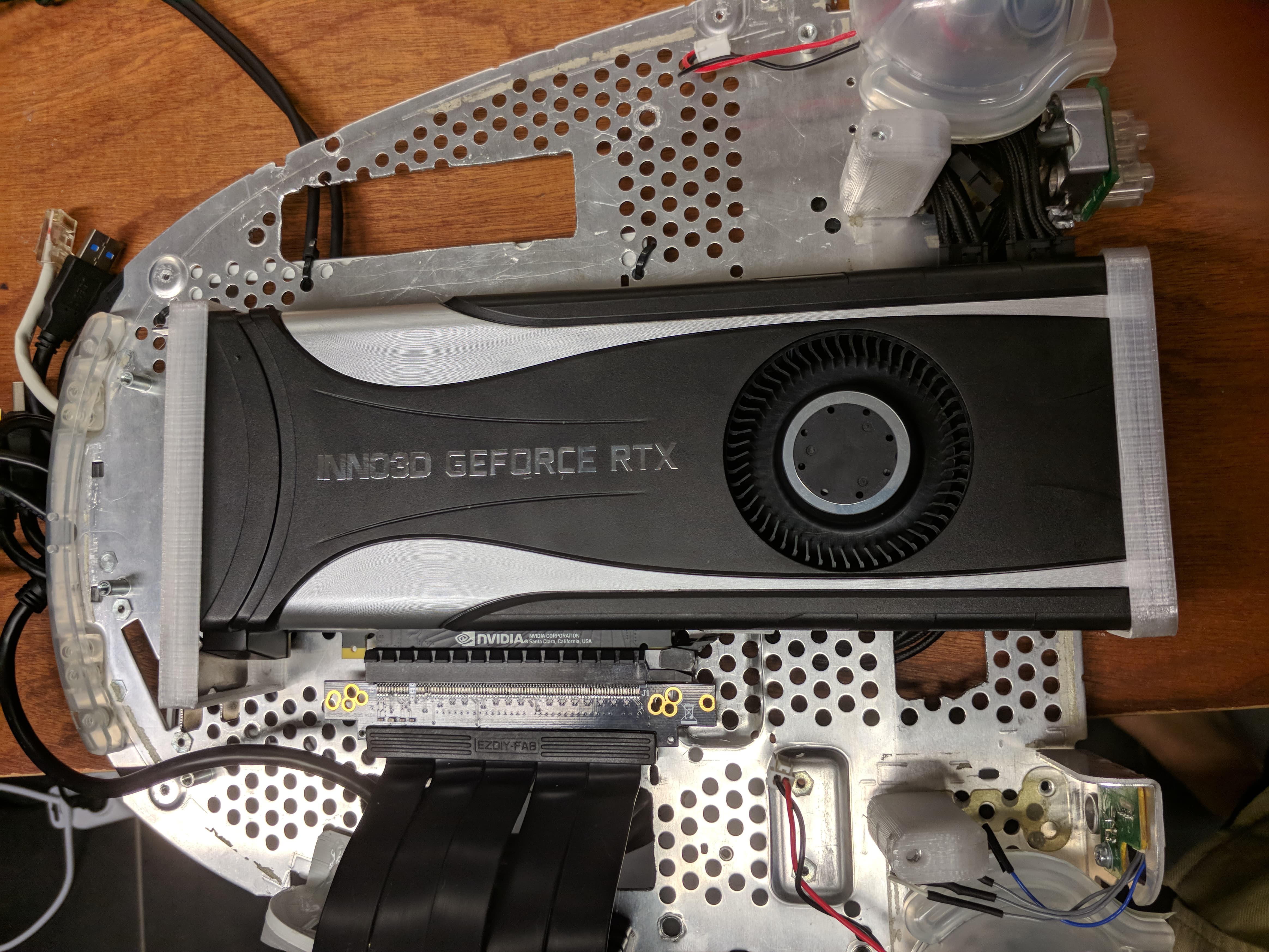 When adding in the GPU it's also important to have the power cable and PCIe extension already plugged in. It's so tight in there that I couldn't get to the connectors when it was screwed in.
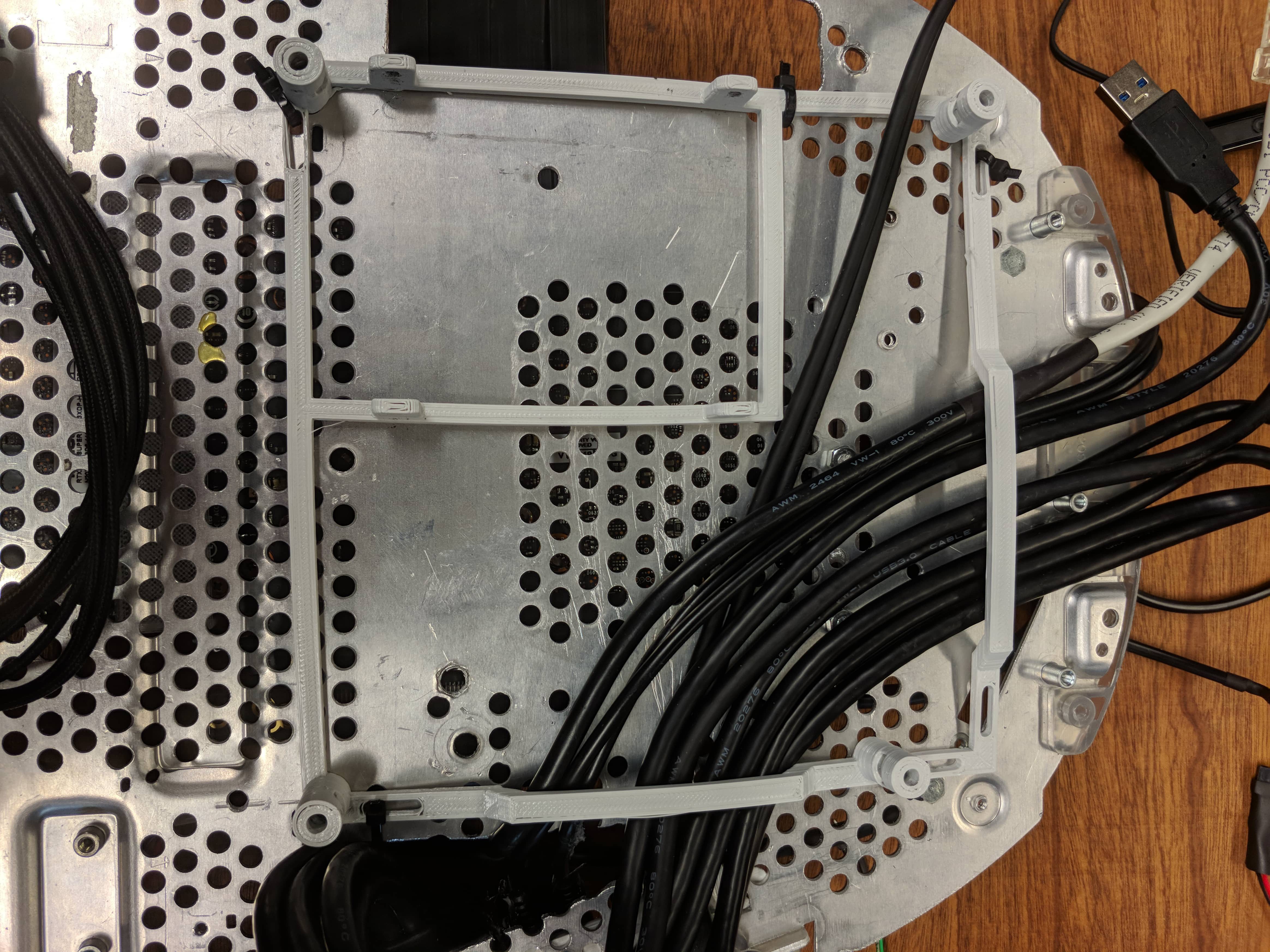


 Hunter Scott
 Mike Turvey
 Kenneth Zaborny
 dbtayl
Which LCD screen did you end up using for the project?