 uri.shani
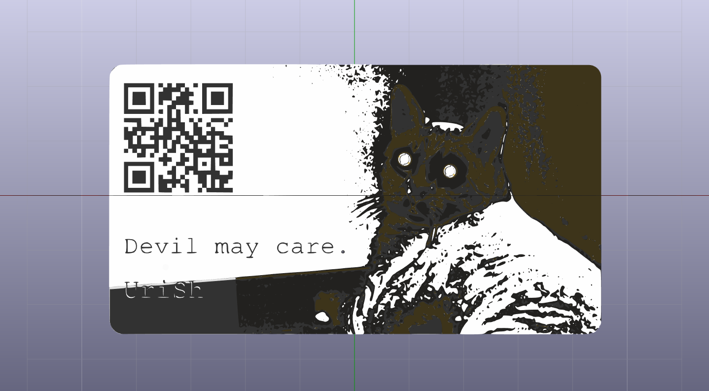
I started doodling with my profile picture in the week after I saw the PCB art video I mentioned. I worked in inkscape, and exported PNG files of the color scheme I decided on: bare FR4, glossy black mask over copper, glossy black mask over bare FR4 on the front side, glossy black mask over bare FR4 on both sides of the board, HASL coated copper for the front side, and white silkscreen. later I found svg2shenzhen, a plugin for inkscape making export to KiCad simpler, which I used for exporting the outline. I wish I found this plugin earlier, as it made exporting to KiCad much simpler - though I found it a bit annoying it only supports square layouts and not rectangular ones or any other geometric shape.
When I decided I want to incorporate a simple circuit on the back, I edited the back copper layer exported from inkscape to a zone by changing it's net_name to GND, which made sure I had a ground plane covering most of the back side of the board to begin with. I looked for LEDs that will shine through the FR4 when mounted on the back facing down, but found their prices to be prohibitive for a throwaway board. I decided on cheap(ish) 1206 reverse mounted LEDs with round flat lenses, which cost less than half(!) the price, and created a footprint in KiCad that incorporated a NPTH in the middle to test those with the board design. I found they're almost exactly the right size for my cat's eyes in the picture when scaled for the card size (which is not exactly the 50x90mm I originally intended - but by the time I found that out I was already too invested in the graphical layout to not go back and change this). Then I looked for a simple, dirt cheap, microcontroller, that I has a working core for Arduino. I wanted the board to be easily programmed via an ICSP header, and be beginner friendly. At first I thought of an ATtiny25 with the ATtinyCore, but then I found microCore, which is built for the ATtiny13, and at about half the cost (again) it made perfect sense.
I then designed the bare minimum circuit I could fit - an ATtiny13a, 2 LEDs w/current limiting resistors, a decoupling cap, a reset pullup resistor, a CR2032 button cell battery (which I found to be the most fitting in terms of both size and discharge current), and a ICSP header. First iteration of the schematic also included another cap and 1M resistor for touch sensing, but I later found there's a library called ADCTouch for the Arduino which does without external hardware.
Next, I set out to test the feasibility of the circuit and code. I stated off with an Arduino Uno, two 5mm LEDs w/current limiting R's connected to pins 5 & 6, and a dangling wire from A0 as a touch sensor. First test was simply to light the LEDs when the cap-sense wire was touched. Next, I decided to add some animation to the LEDs - making them pulse, somewhat like the iphone button. I thought that that is a fitting (and surprising, hopefully) animation in a setting such as handing the card to someone. I found a function that does just that here, than some further digging got me to a non-blocking implementation, so I could check for for touch sensing between changing of the LEDs intensity. While that worked, and is quite elegant, for this particular use there's no reason for using the function and the included sub-functions, as well as using floats. So instead, I used a spreadsheet to get the desired values, and truncated the values to 8 bit values so I could than store those as progmem bytes and save some space. I then exported that to CSV, and edited the text file a bit, saving it as a .h file, and including that in my Arduino sketch.
Once I got the code down to a manageable size I chose my components for size, weight, and price. I chose a SOIC8 package for the ATtiny13, 1206 LEDs, 0805 180R's and 0.1uF C, and a bent metal battery clip. The ICSP header was laid out finished the design of the PCB using the footprints of the components I chose. Layout was done in such a way...
Read more »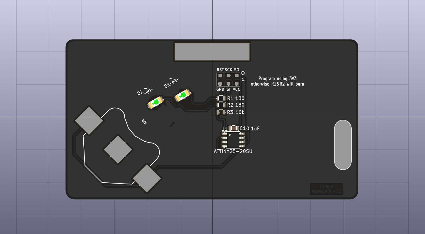

 doctek
 rrace001
 zakqwy
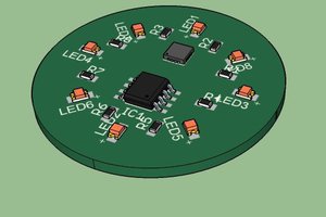
 Luc
Luc
you did a great job making this VN Video Editor Mod APK unlock every program object I want to embed with my webpage you can see it here,https://vnvideoeditorapk.com/