 Jan Bert
Features
- All-in-one solution for playing VST instruments
- Dedicated for live-performance with rotary controls and buttons
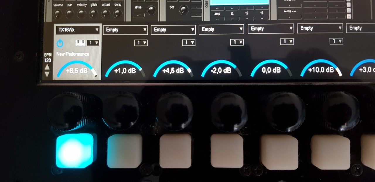
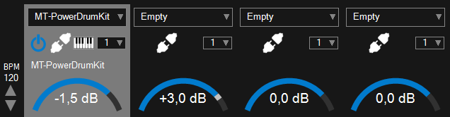
- Real-time control of 8 VST instrument and effect channels
- Midi input
- Integrated mixer with multiple I/O and headpones output
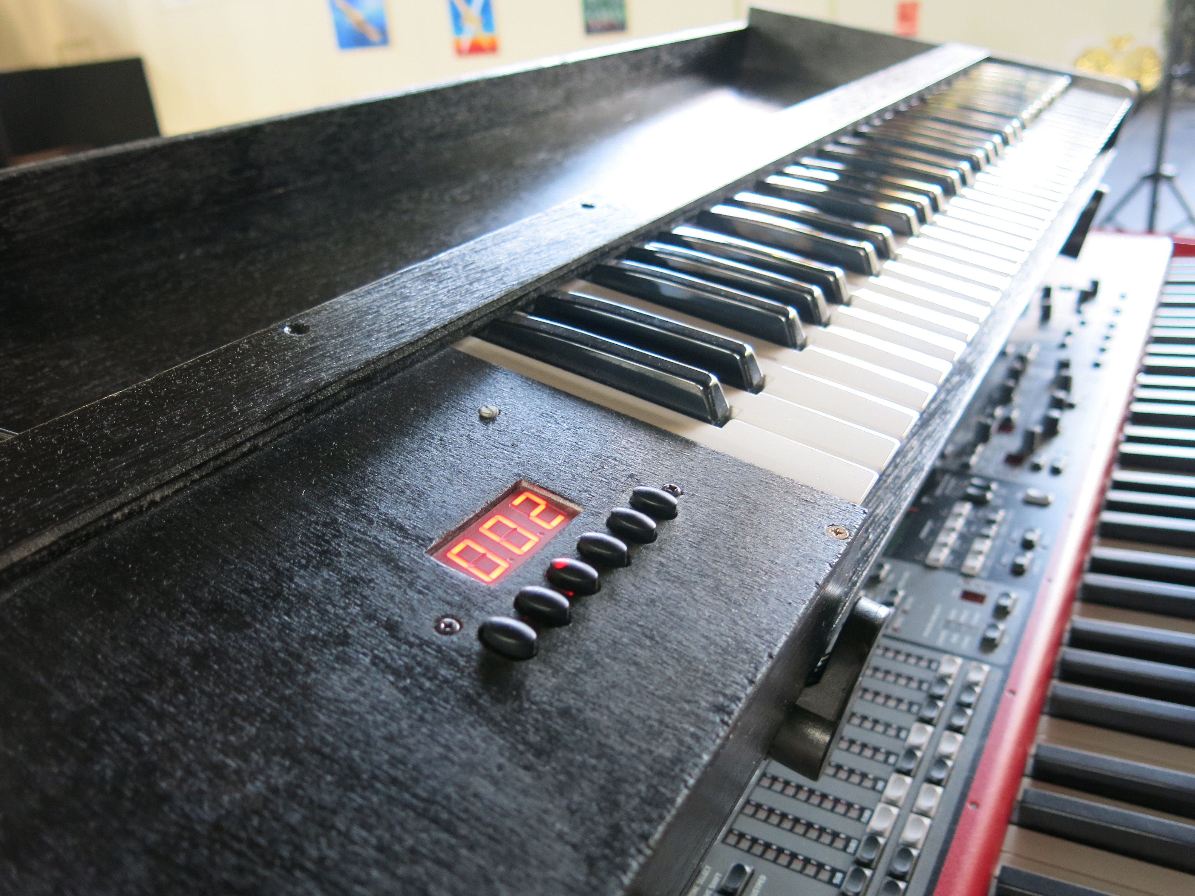
- Switching between songs/banks
- Setlist editor with song/bank selection
- Powerfull PC platform for heavy VST's
- Low latency audio
Philosophy
You might ask why I didn’t buy a VST control keyboard like the AKAI Advance or Native Instruments S61 mkIII. Those are excellent midi controllers especially made for playing VSTi’s. The reason is because I would still need a separate laptop/MacBook, mixer and audio interface and hook them all up with the midi, audio and power cables. Other solutions exist like the V-machine and vPed, but they lack the processing power of my Intel I5. A Muse Receptor is also not an option because it is something you put in a rack, and not on top of your keys. It is also above my budget. The AKAI MPC (X) is looks awesome, but cannot run VSTi plugins standalone without a PC. I want to have an all-in-one solution, transport as few things as possible and plug in as few cables as possible when I go to a rehearsal or gig.
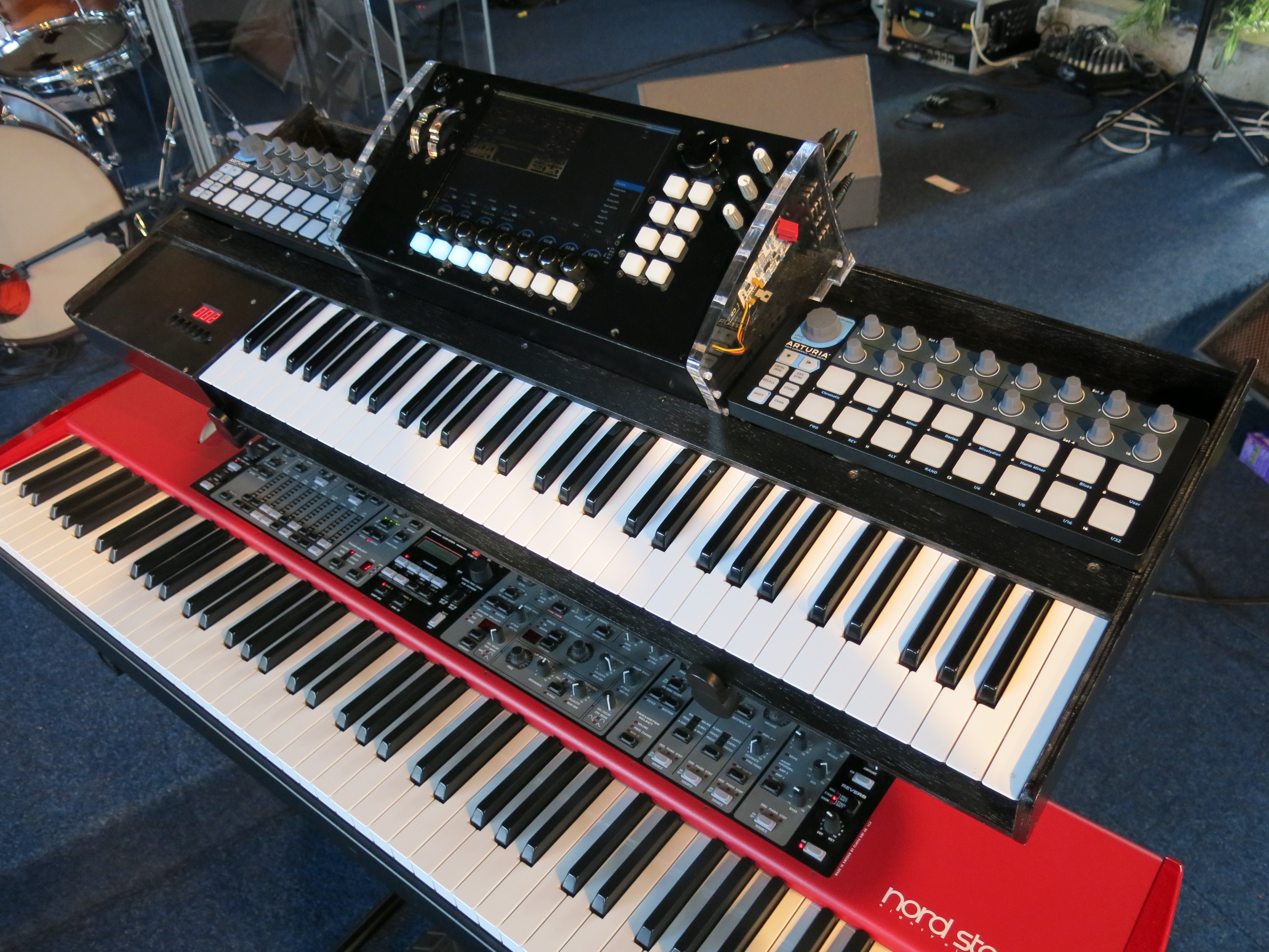
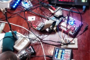
Components
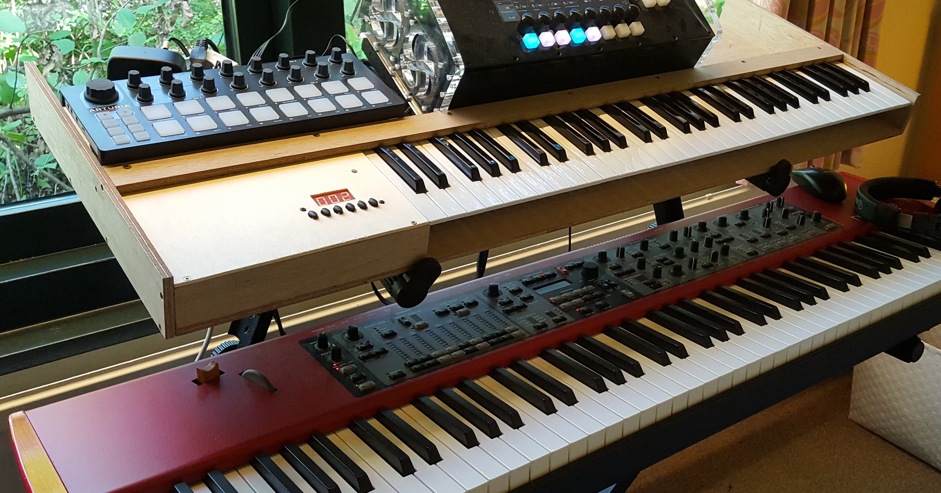
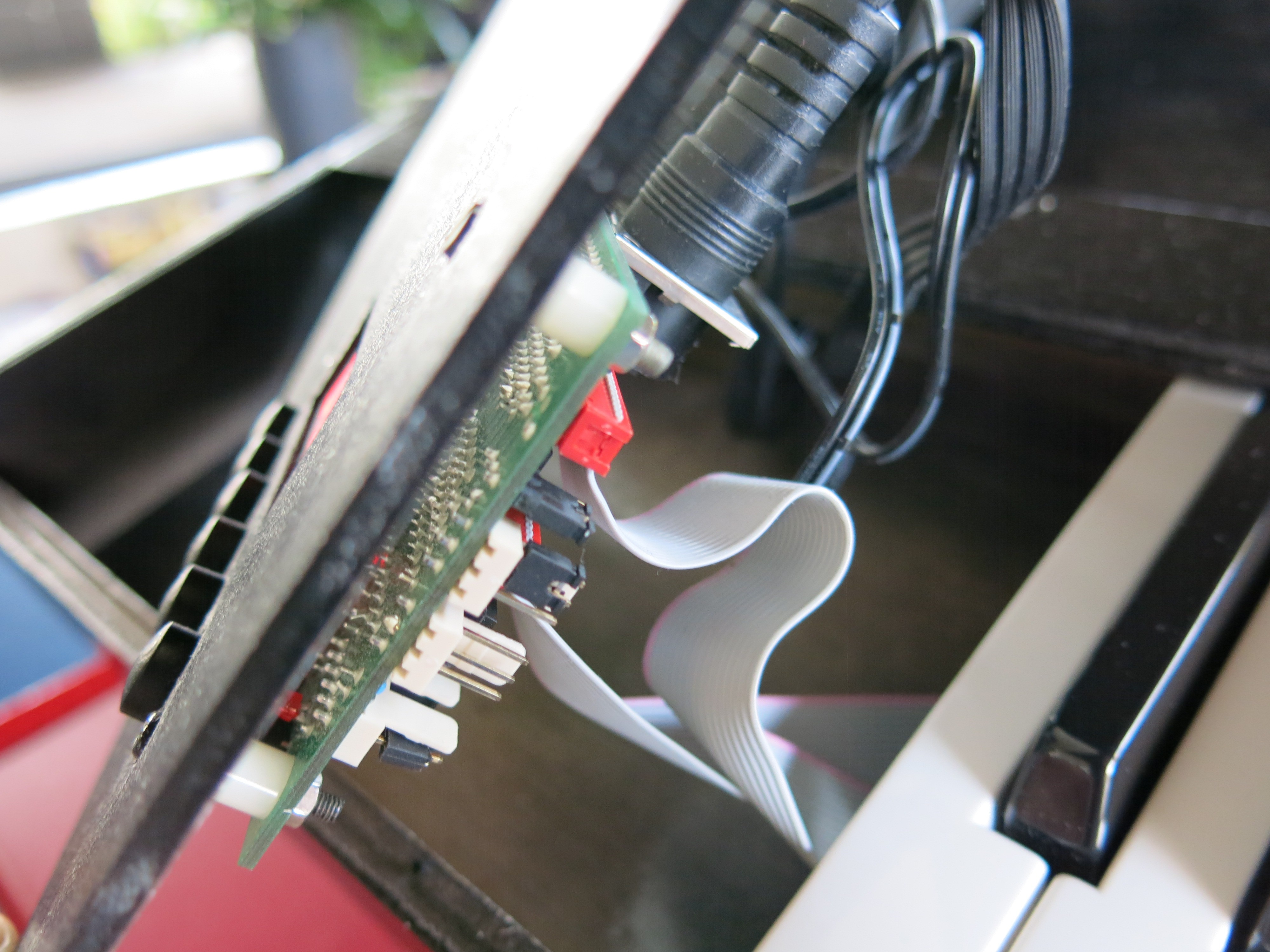
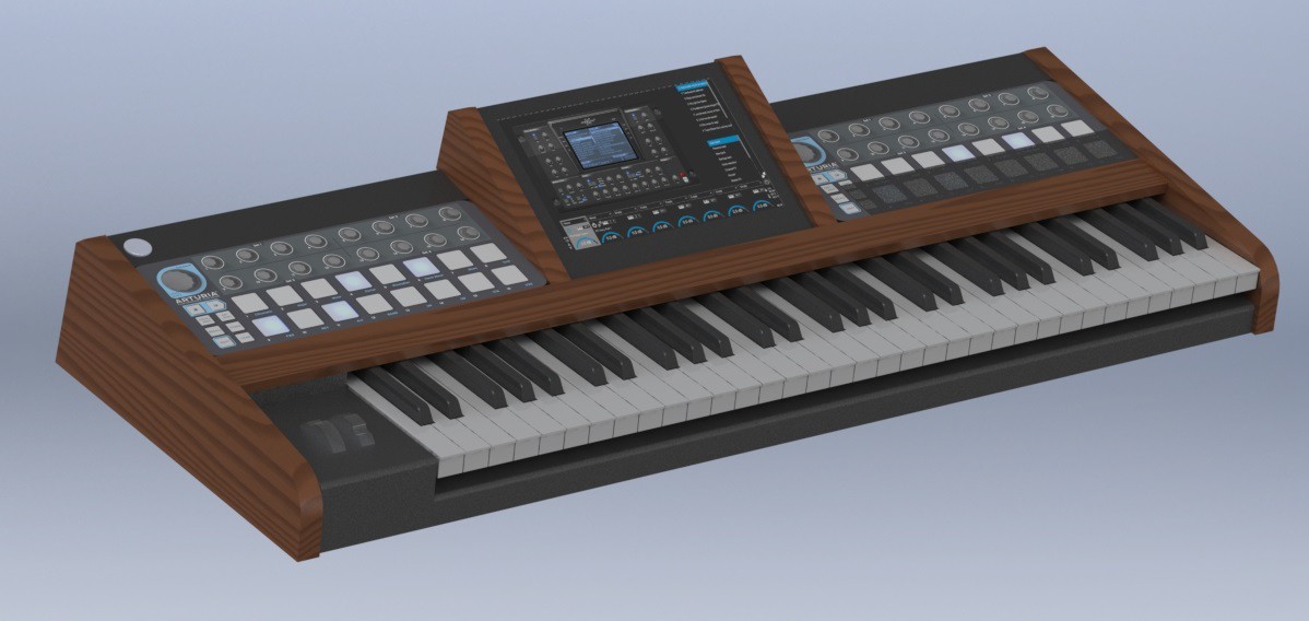
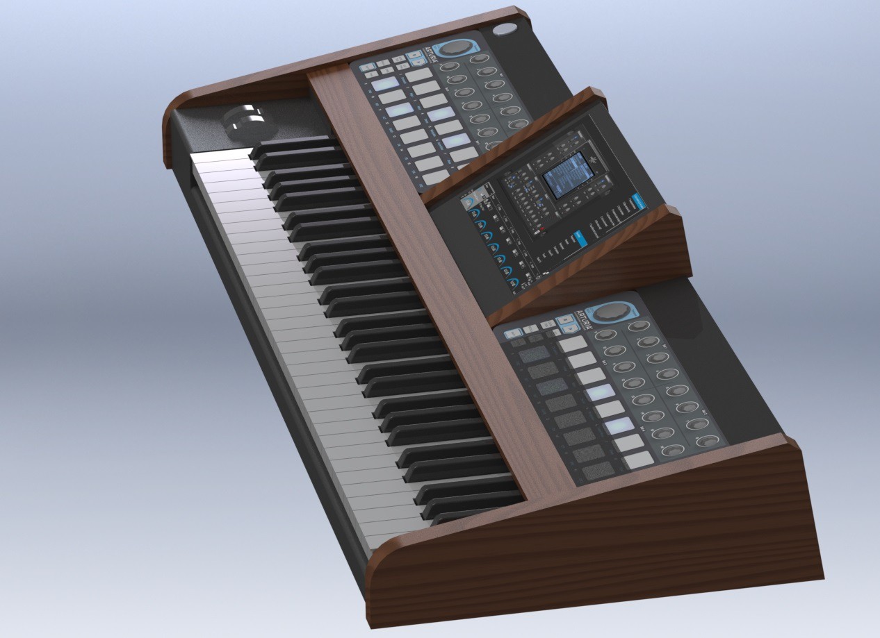
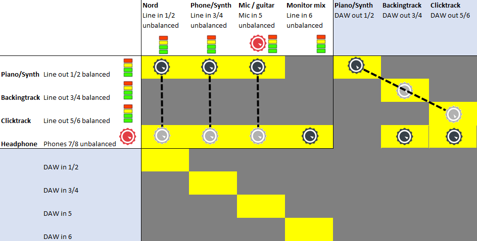
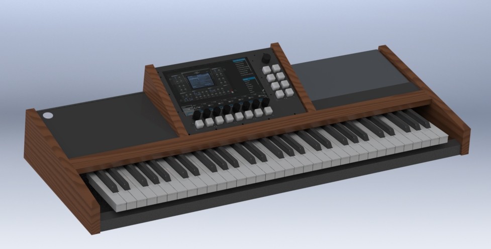
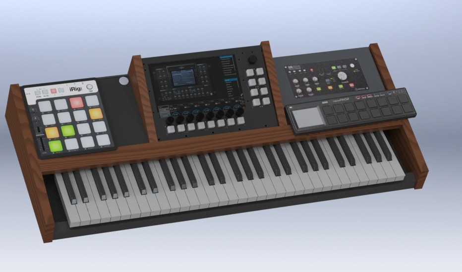
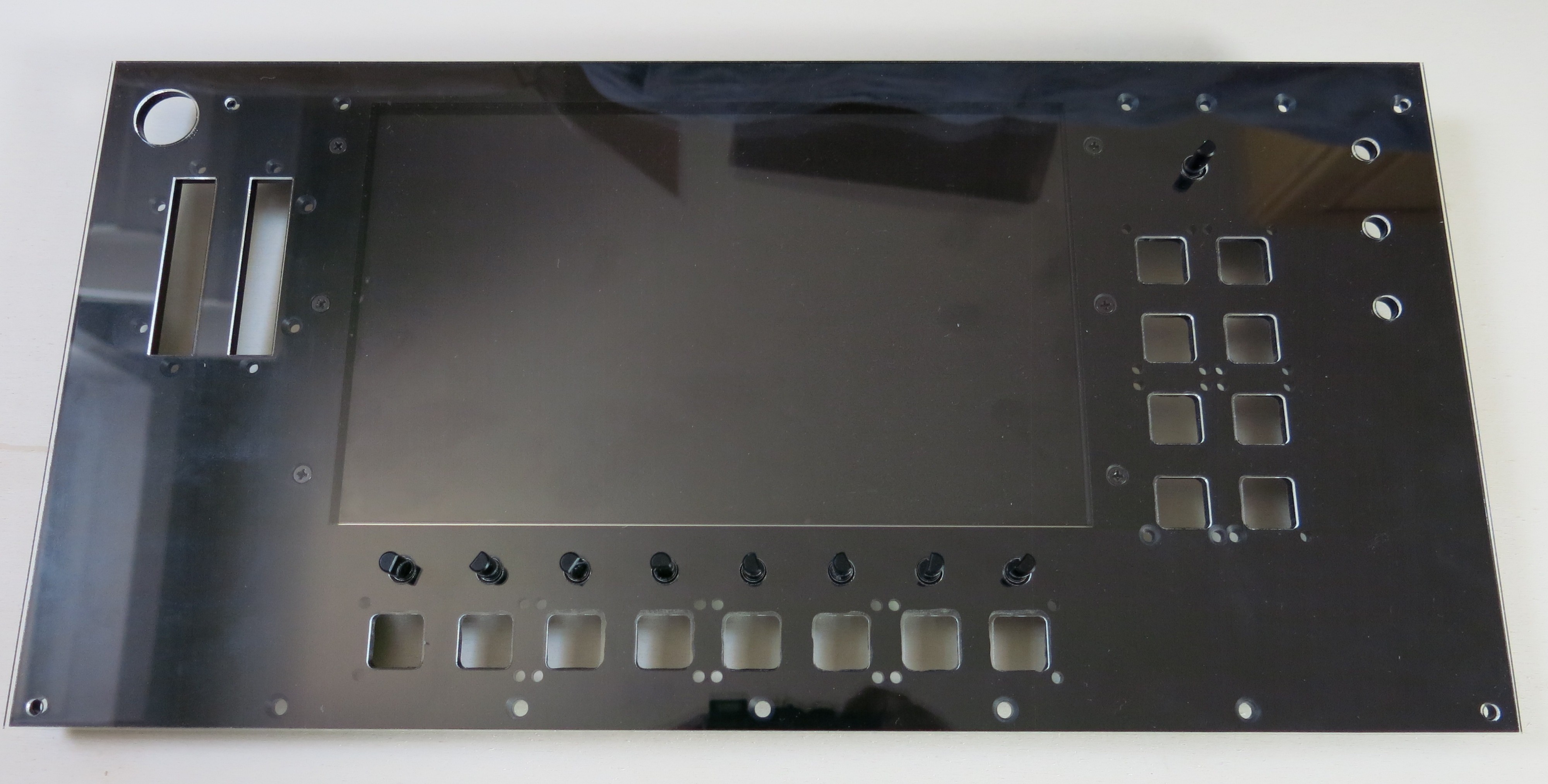
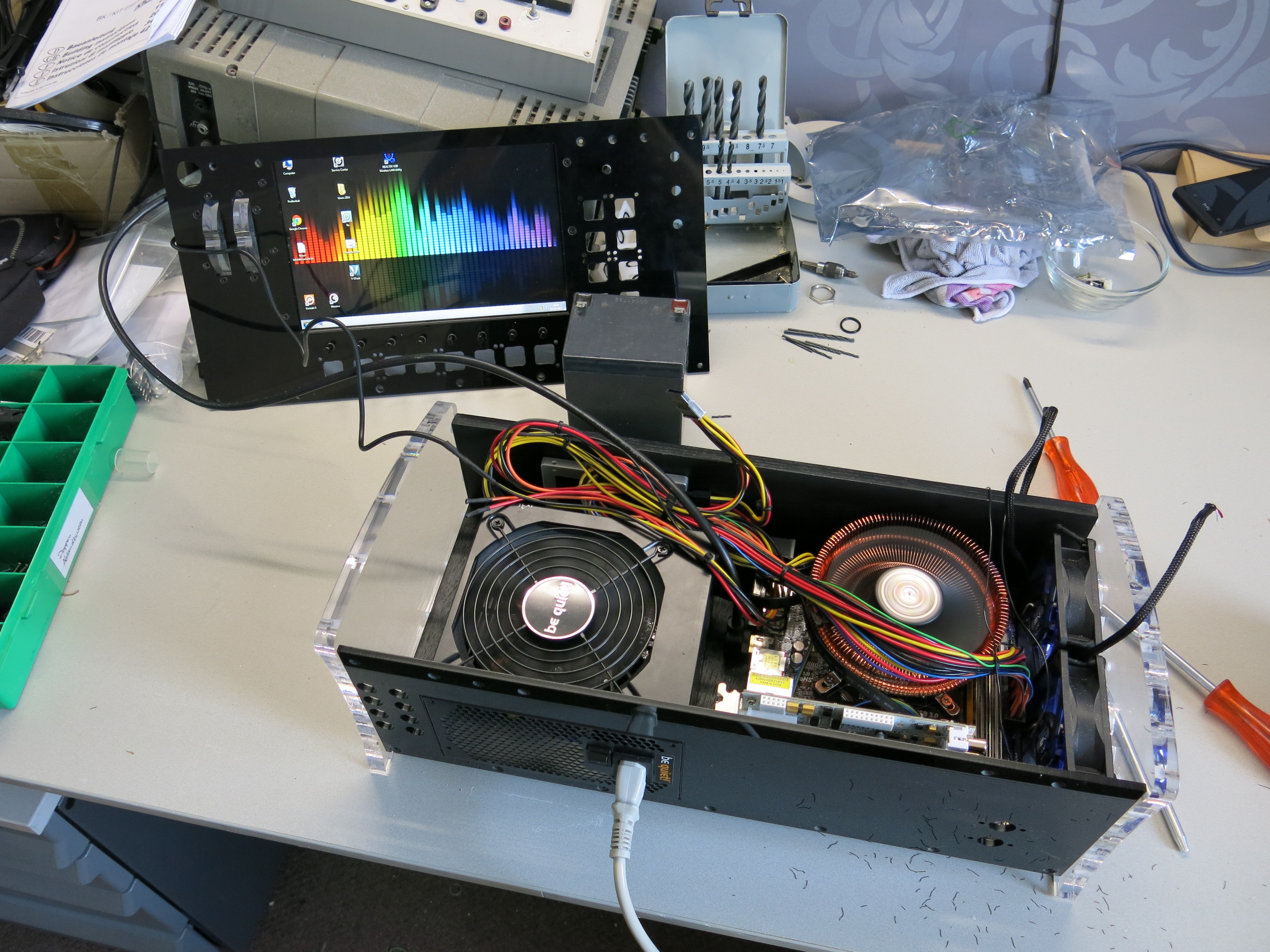
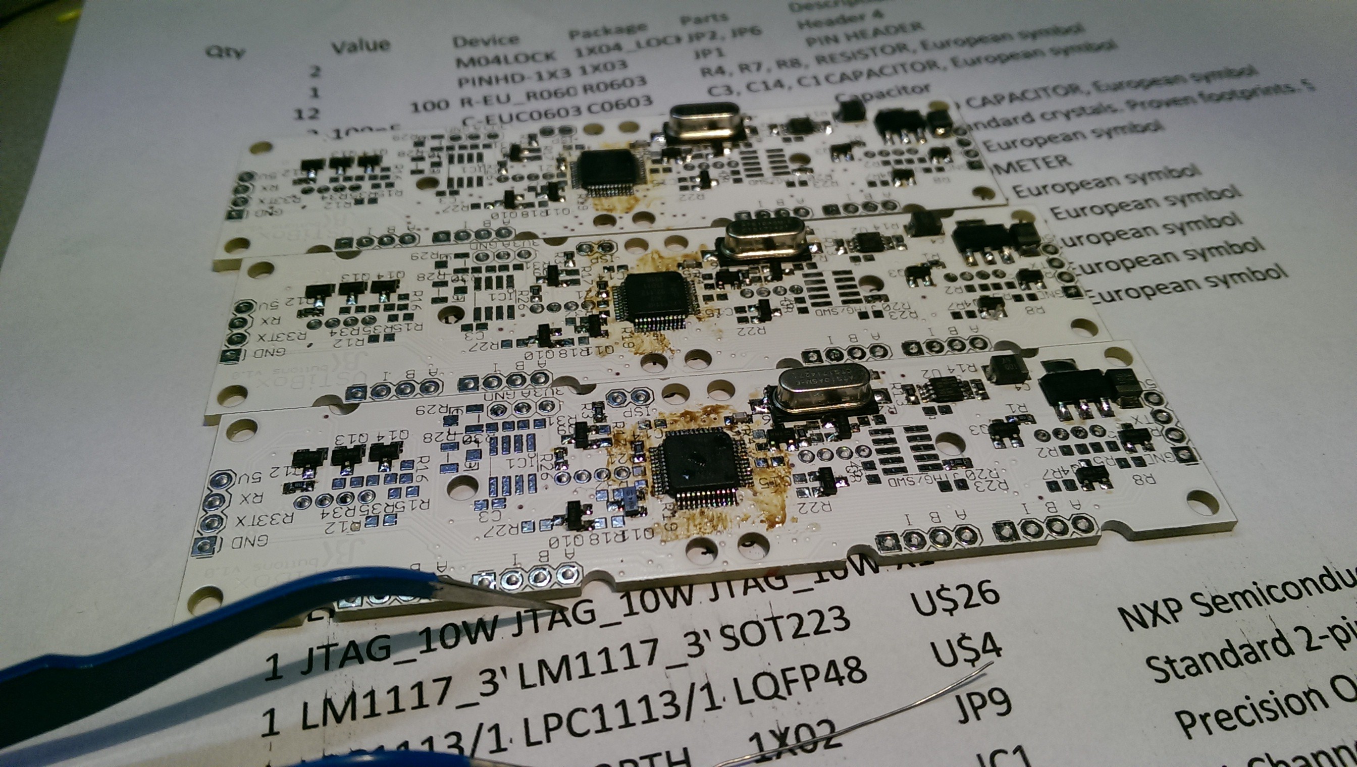
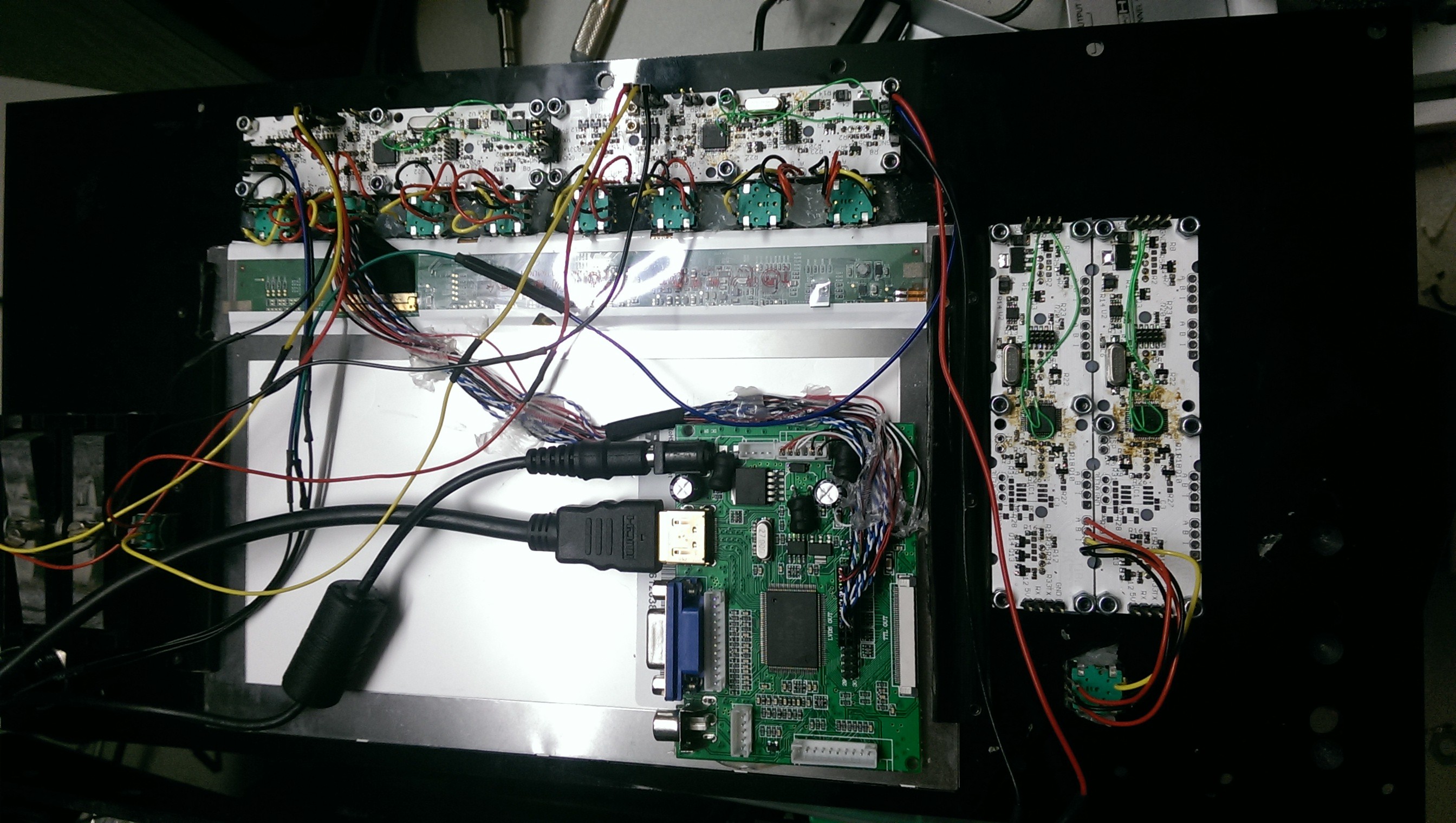
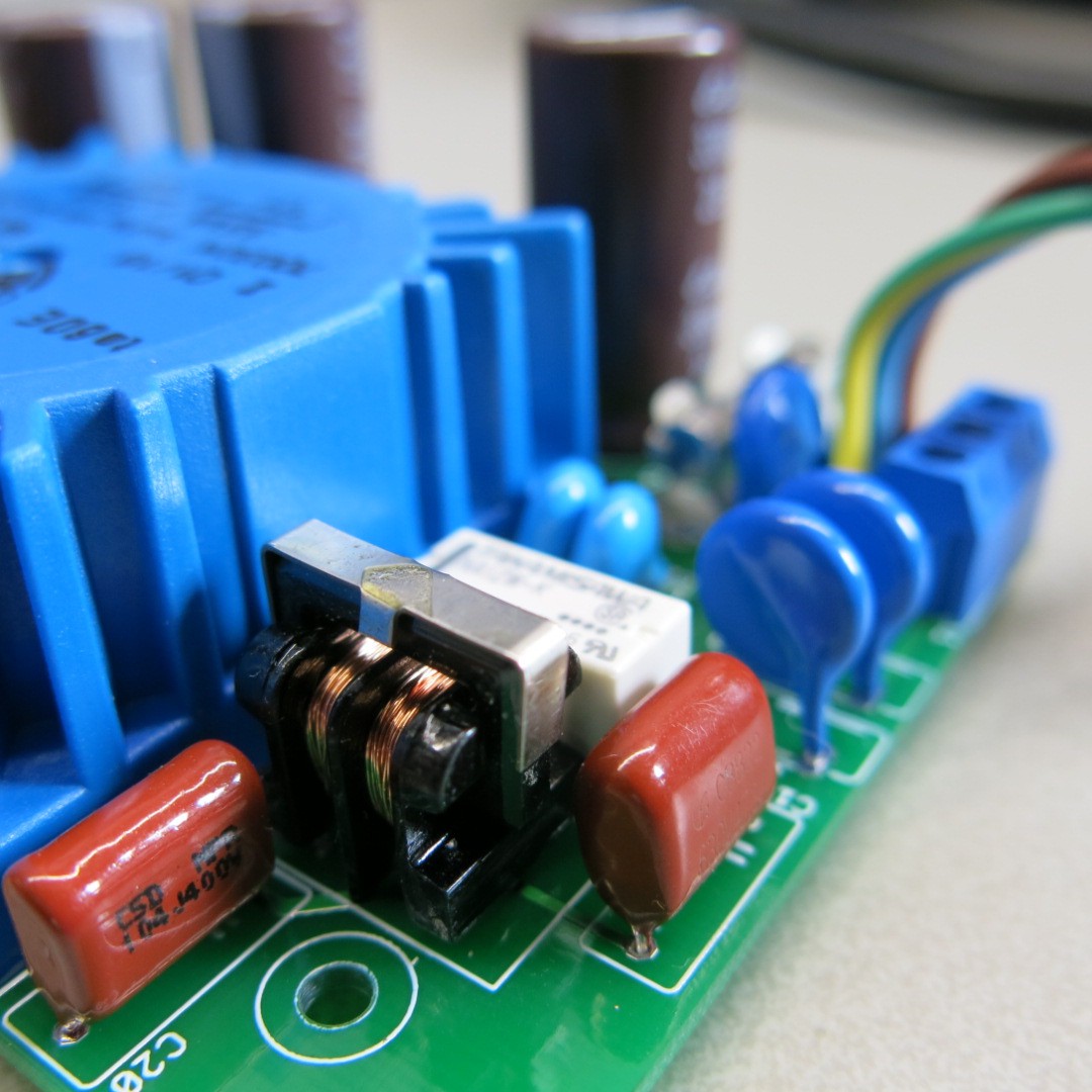
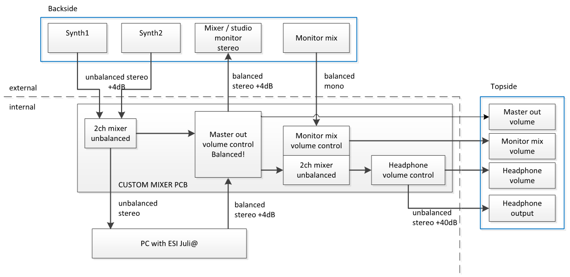
The VSTiBox is build around a Windows machine equipped with an PCI Express audio interface, that runs a custom VST host (DAW) written in C#. The VST host receives midi input from a master keyboard, in my case a Nord Stage EX. Eight VST instrument channels are controlled by a number of encoders and RGB illuminated buttons for setting their volume and toggling the channel on and off. The audio ouput of the audio interface is routed through a mixer. The mixer combines the VSTiBox audio with two external stereo channels before it is sent to the master and headphone output. It also features a monitor input that is not routed to the master output, but only to the headphone for use on stage. The mixer is powered by a linear power supply which is a slave of the ATX computer supply. Besides the PC platform and the audio interface, all components are DIY.
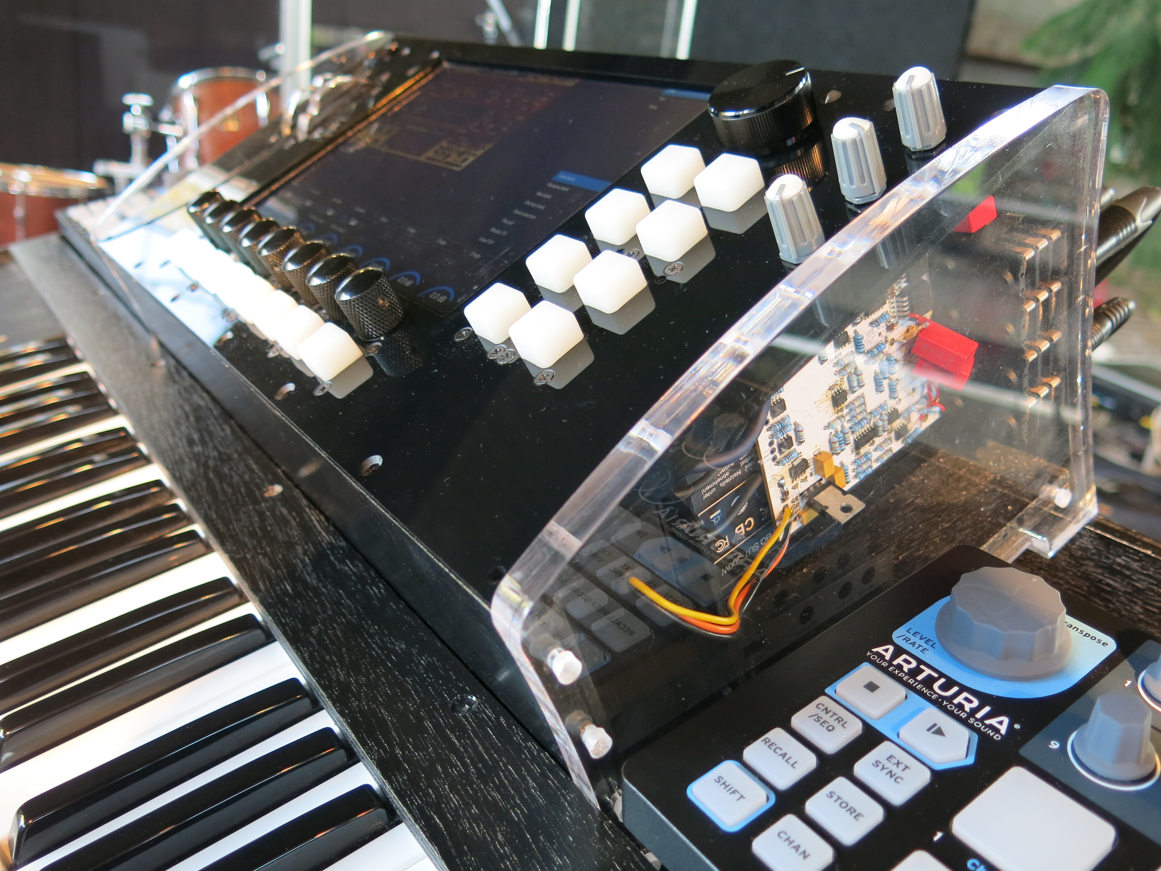
Design
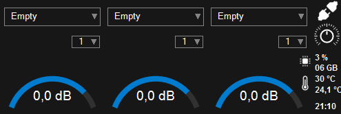
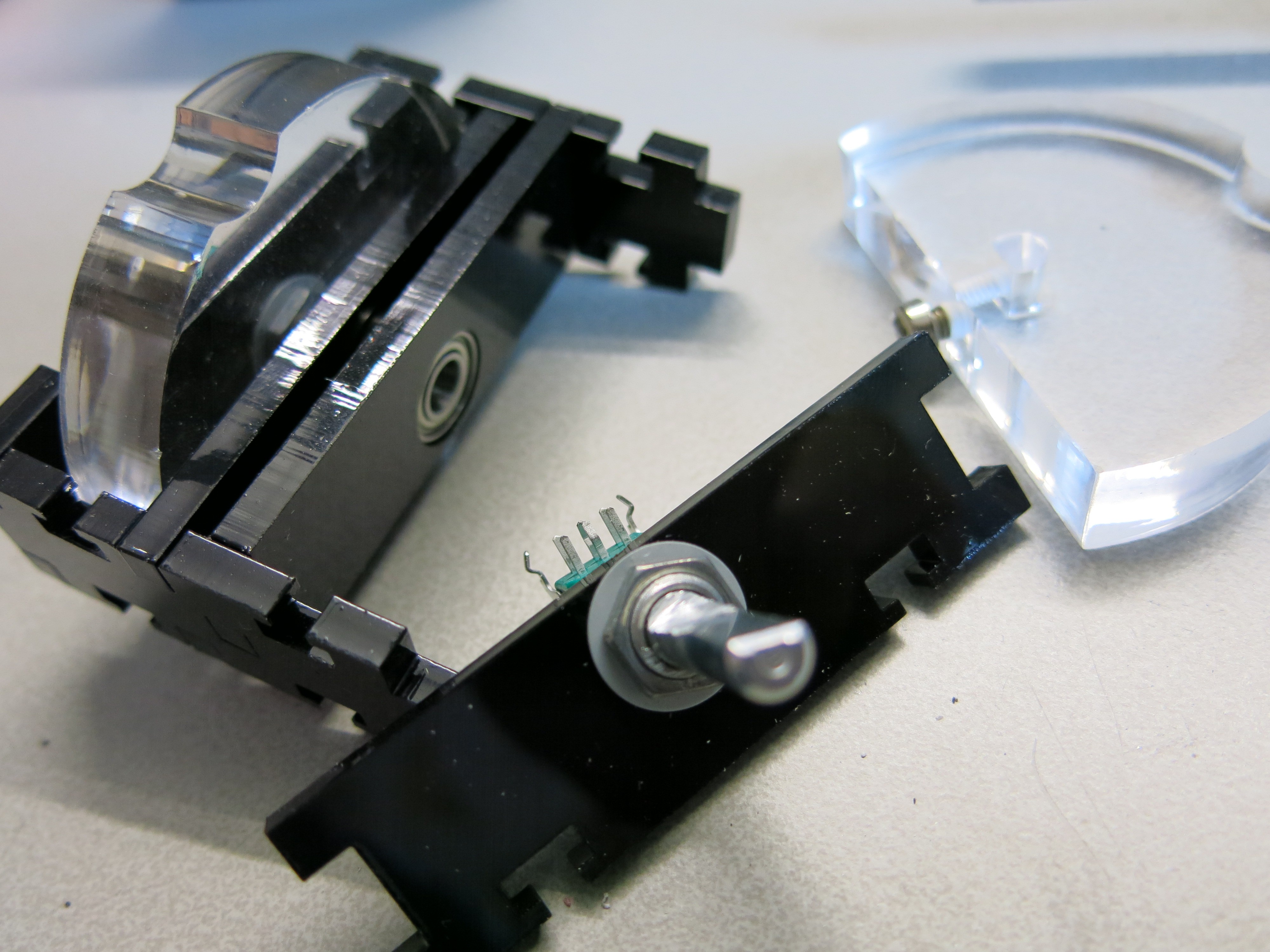
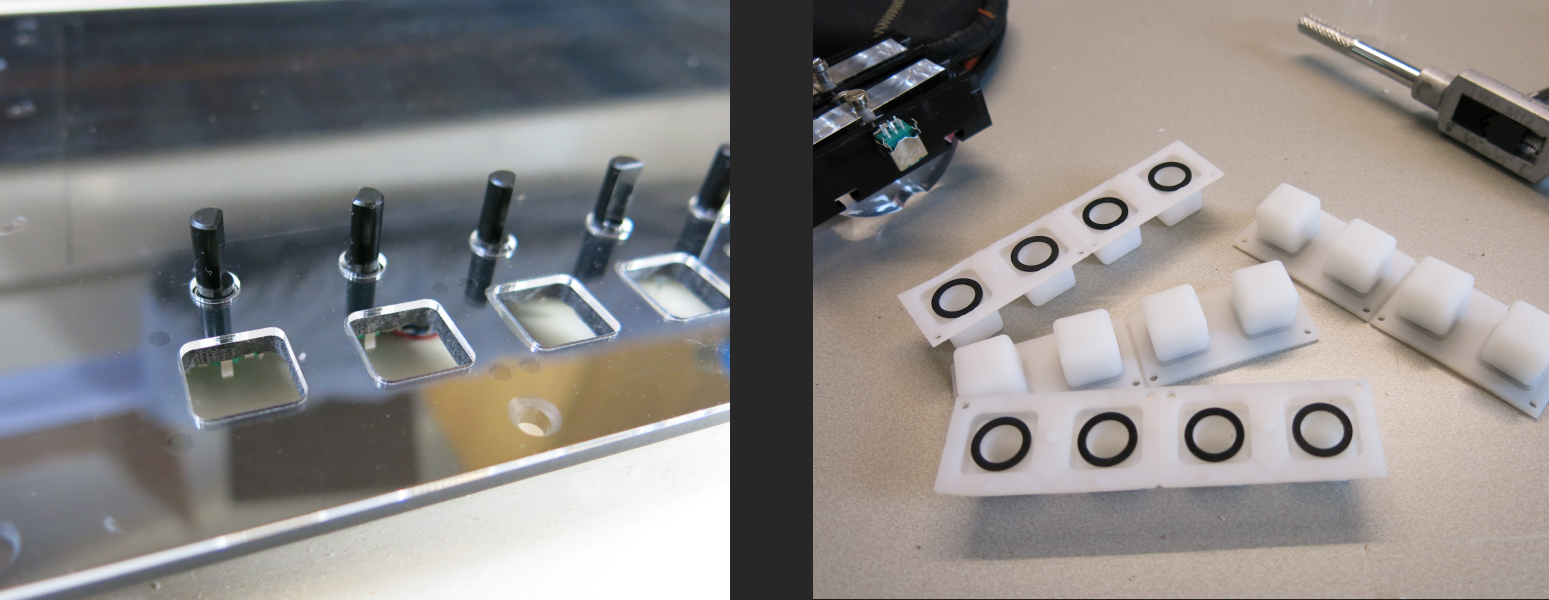
When playing live VSTi's you want to focus on playing and be able to switch sounds instantly by reaching for physical knobs and buttons which clearly show their state or value. Mouse handling or touchscreen presses are prone to error and therefore out of the question during a gig. This is why the system has no touchscreen. It does have a wireless mouse and keyboard connection for preparing banks and setlists. Although my original plan was to have no touch support, I now miss it very much and plan on adding it. Inspired by the Elysium C# controls theme, I designed an interface where a physical encoder is positioned directly under the screen, and the value of the encoder (volume/pan) is directly displayed graphically above the knob.
Hardware
Obviously the audio latency must be as low as possible. The ESI Juli@ XTe with PCIEXpress has a single +4dB balanced stereo in- and output with a perfect low latency. It is the first affordable low latency interface I could find thanks to this performance benchmark.
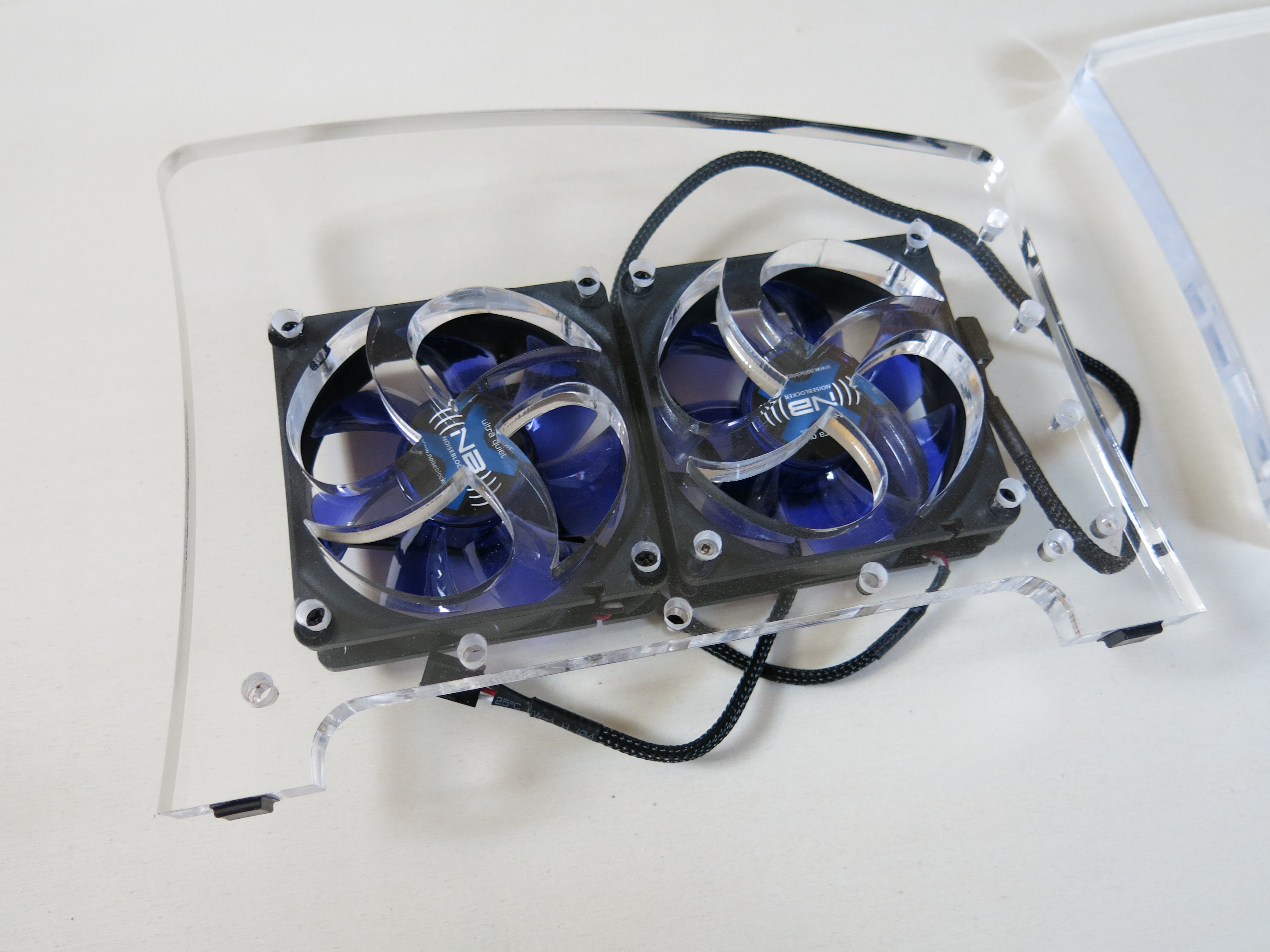
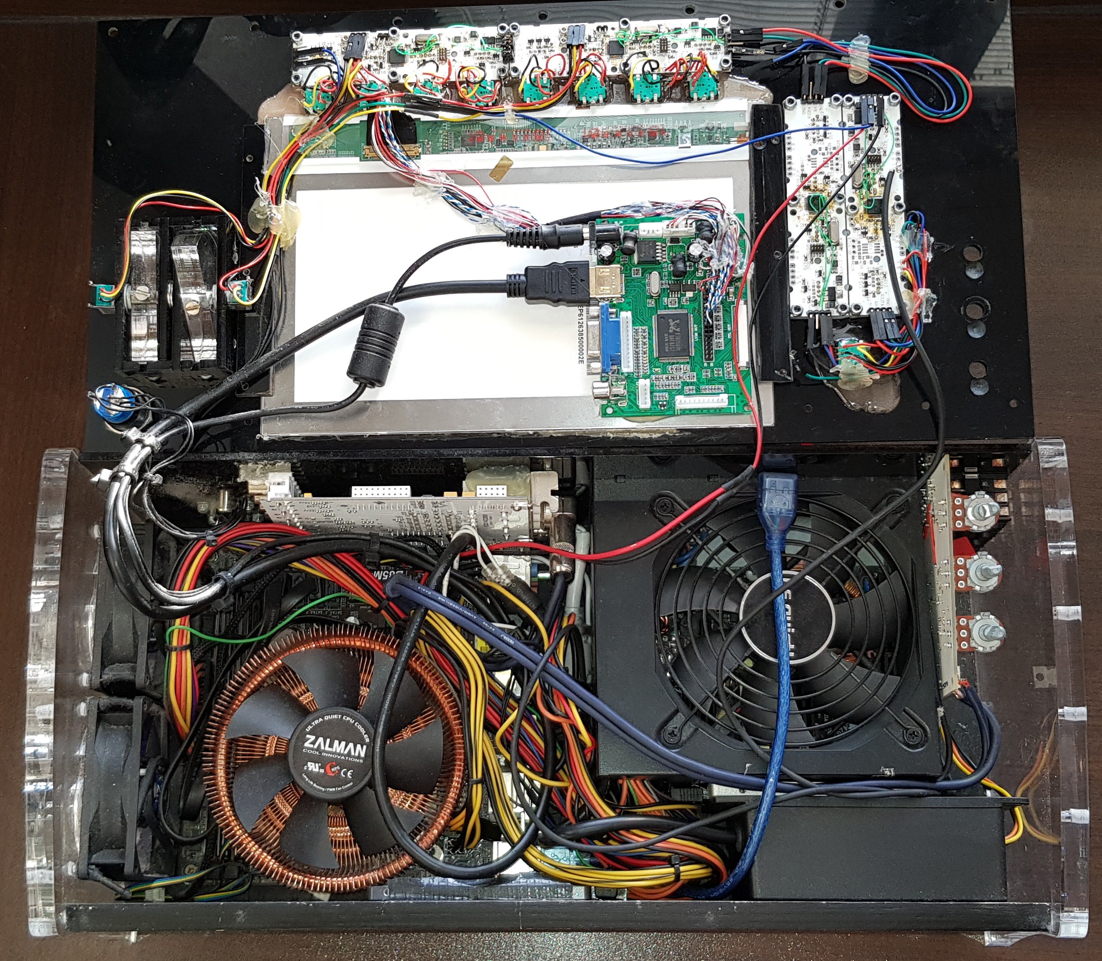
The Juli@ is mouted on a micro ATX Asrock B85M running an Intel Core i5 4460 with 8GB DDR3, which was a prefectly good choice back in 2014. Cooling is provided by a copper Zalman CNPS8900. It is equipped with a 256GB SSD, with an aditional one added later.


 Patrick
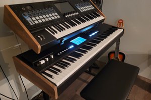
 stupid
 Kenneth Marut
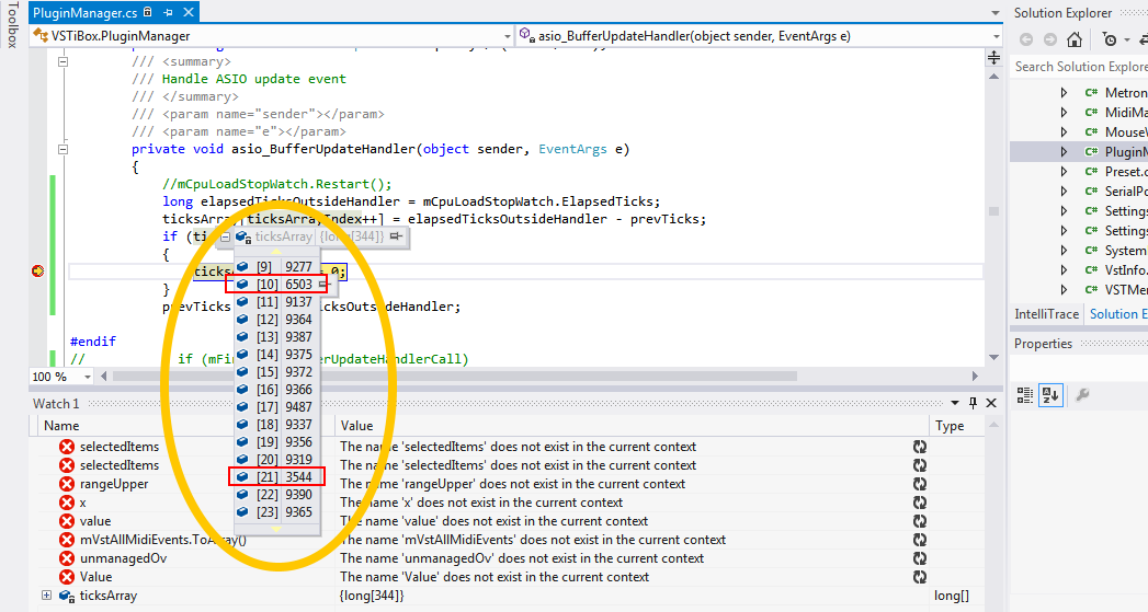
Brilliant!! and just the type of project I love. I'm learning to write VST's (C++) at the moment and playing around with pureData. Did you get around to re-writing C# to C++? or was C# good enough?