 T. B. Trzepacz
Initially, I was not really sure it would be economical to manufacture in China, and so I wanted to make sure that I could self-assemble these easily and economically. The design was based around commercially available "maker parts" that had cheap knockoffs on AliExpress available in quantity. So the STM32F103C8T6 "Blue Pill" board, 16 LED WS2812B ring, and XM-M125 Amplifier were all chosen.
But after the blinky heart pendant project, I felt more confident about manufacturing in China, so I endeavored to integrate the parts of these boards so that the whole thing could be assembled without the need for daughterboards. In order to do this, I had to actually make sure that I knew what parts were in these boards, and ended up reverse-engineering them to make sure I could get it right.
The LED ring
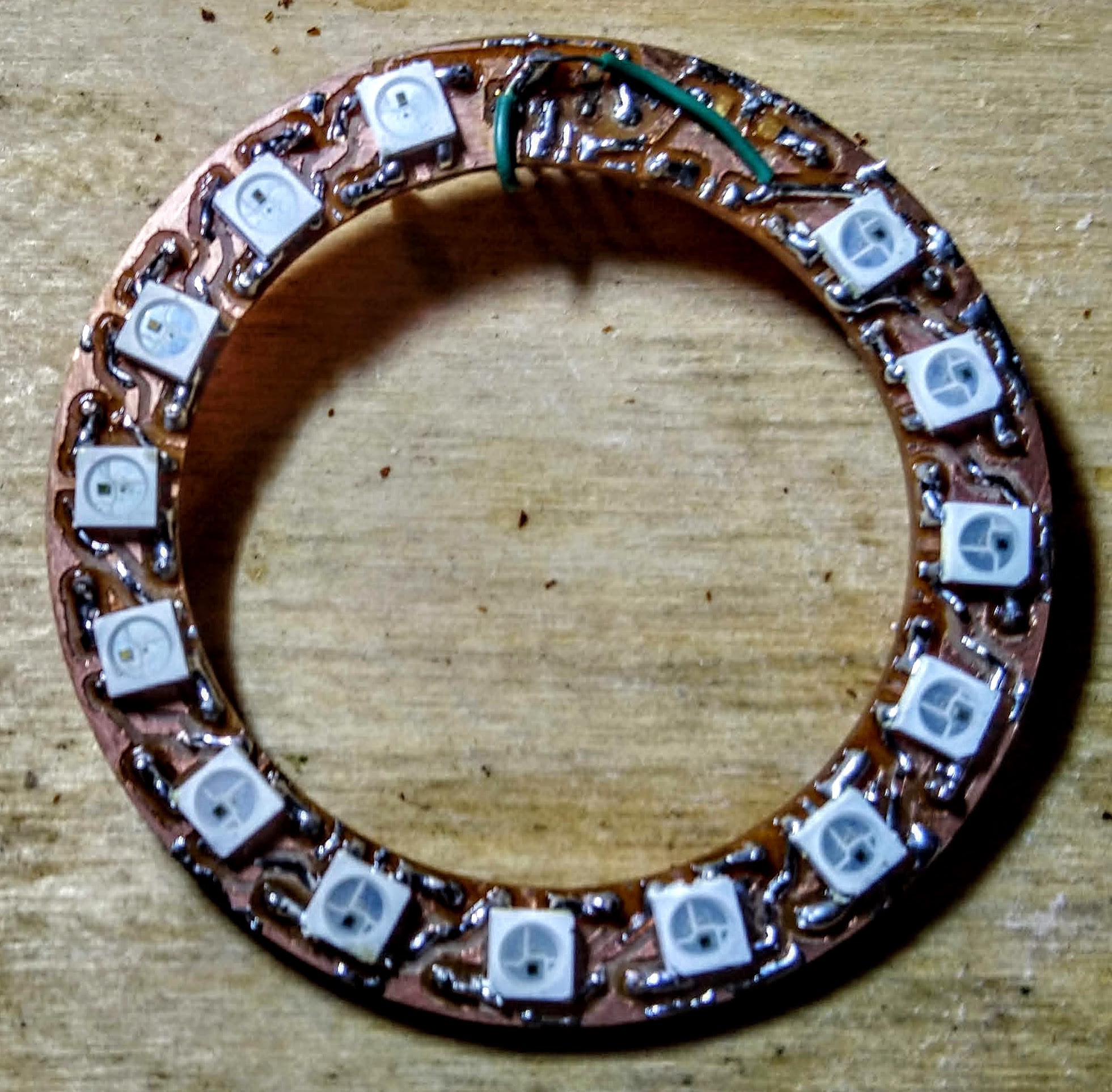
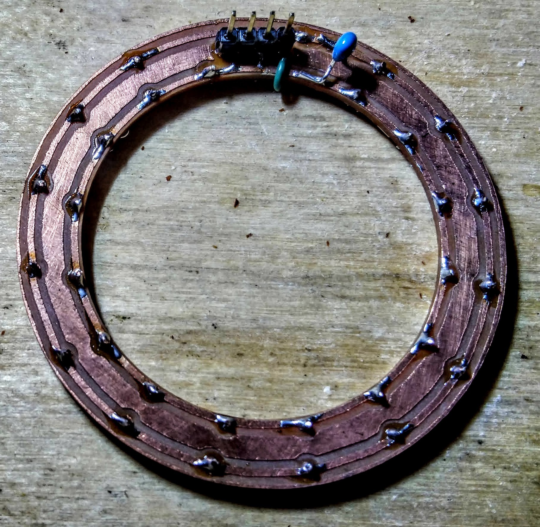
The LED ring seemed pretty simple, but ended up causing a bunch of problems. Splitting the main board down the center of two of the LEDs meant that they were never going to line up. Also, there were vias below the top LED, which is fine for a manufactured board, but is a bad idea when you are milling your own boards that don't have plated through vias and have to solder a wire in each one.

So, after the main board became such a mess, I decided to split the LED ring off and cut it separately. I had made a place for a pinheader for the commercial LED ring, so I thought by splitting off the design into it's own board I could debug it more easily. (I did have some LED rings that I ordered from China, but they were 12 LED rings because I wasn't thinking about how 16 would give me better capabilities for music stuff.)
So I cut the board, and it had problems. Soldering the header under the LED didn't work as well as I wanted, and I had a terrible time soldering the first few SMD LEDs, and they ended up misaligned. In trying to correct them, I think I overheated the first LED. It didn't work.
I found out that the LED ring was supposed to have a capacitor on the power leads for every LED. I didn't want to waste 16 caps on this bodgy board, so I just added one to see if it helped. It didn't seem to make much difference, but I did notice that the board would kind of work if I put some stress on the connector, which led me to the realization that the solder joints for the pin header that were under the LED just were not making connection.
So I added some bodge wires for those vias, but I was still having troubles, so I desoldered the first LED (taking some traces with) and bridged it. Now it was working, but the 2nd LED seemed stuck on. So I desoldered that, intending to replace it, but it took a ton of traces with it, so I ended up bridging that too. Eventually I got it working.
So my 16... 14 LED ring was finally working. I suppose with some time I could bodge together something to get the first two LEDs back in, but I decided that I should get the other aspects of the project moving and save LED stuff for the do-over on the full board.
The amplifier board
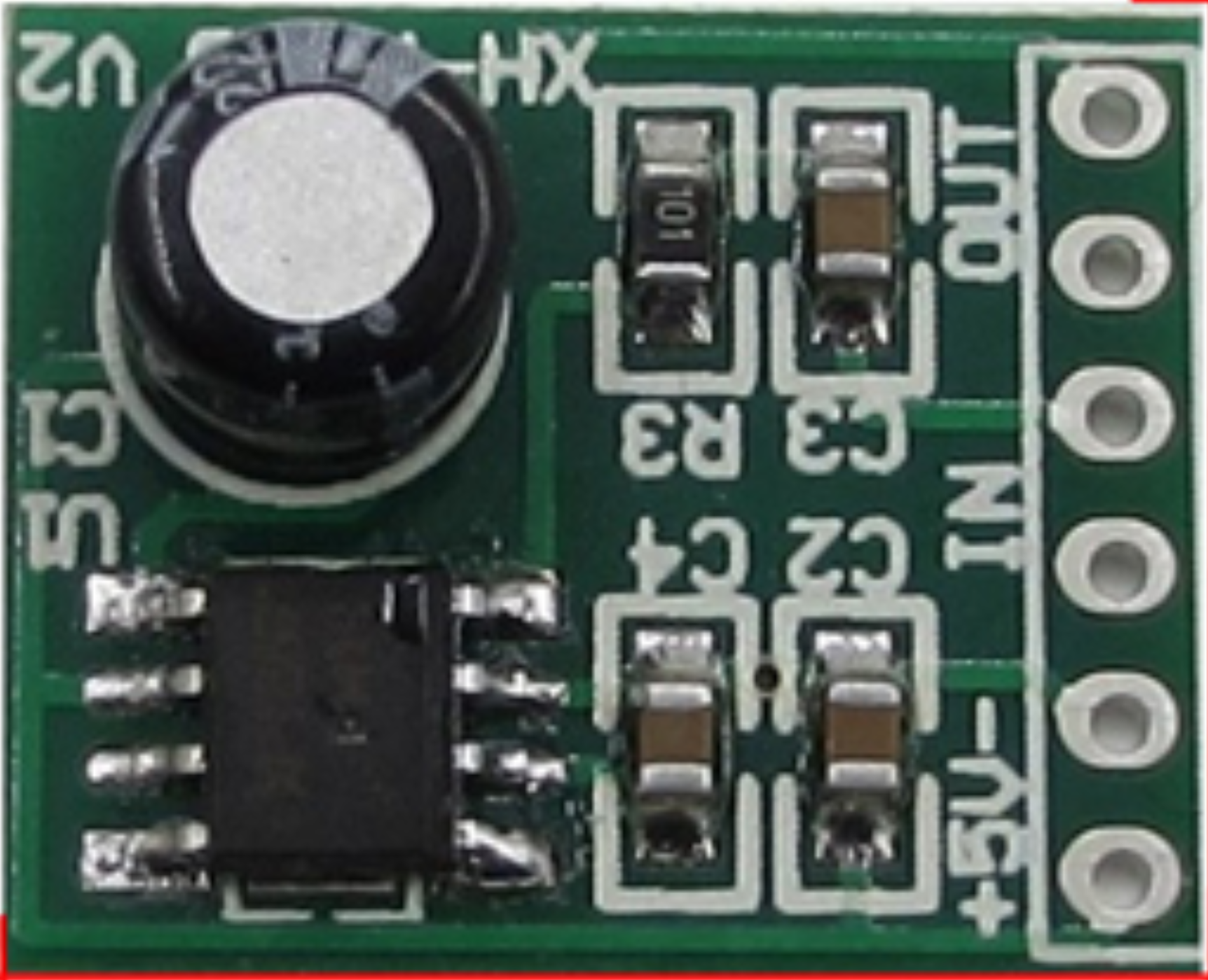
The amplifier board was much simpler. Although the circuit didn't quite match what they had on the manufacturer's AliExpress page, between that and careful examination of the board I was able to work it all out.
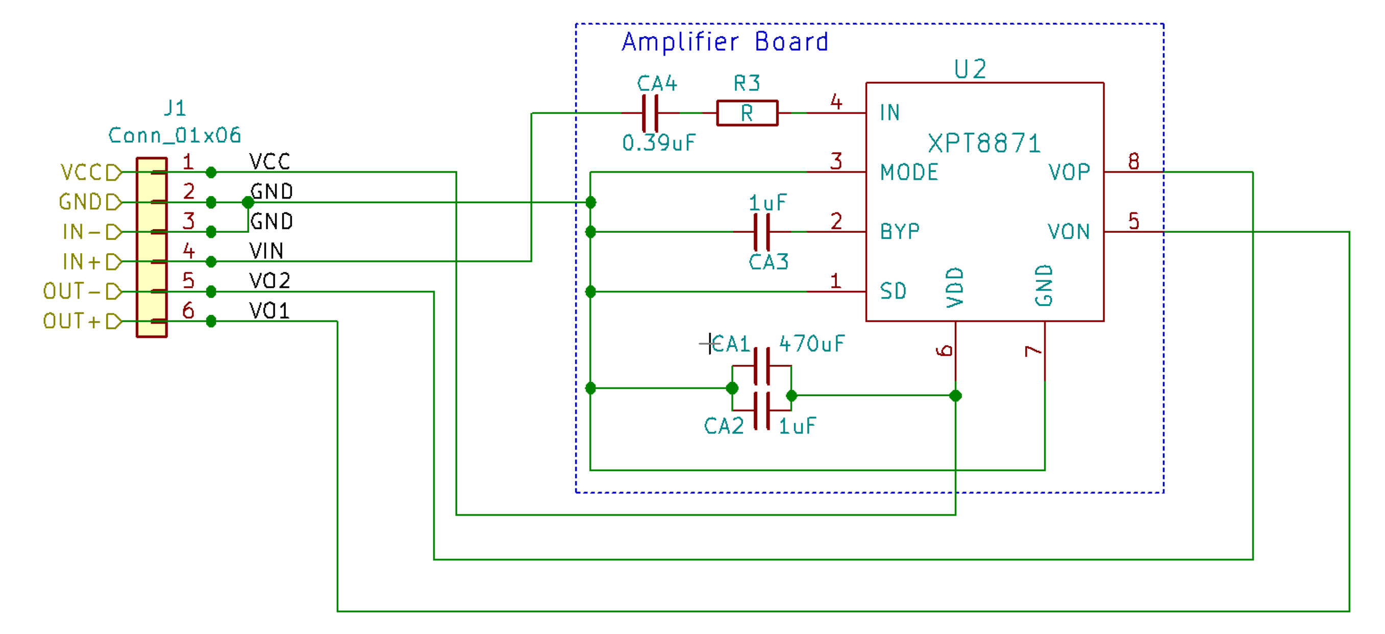
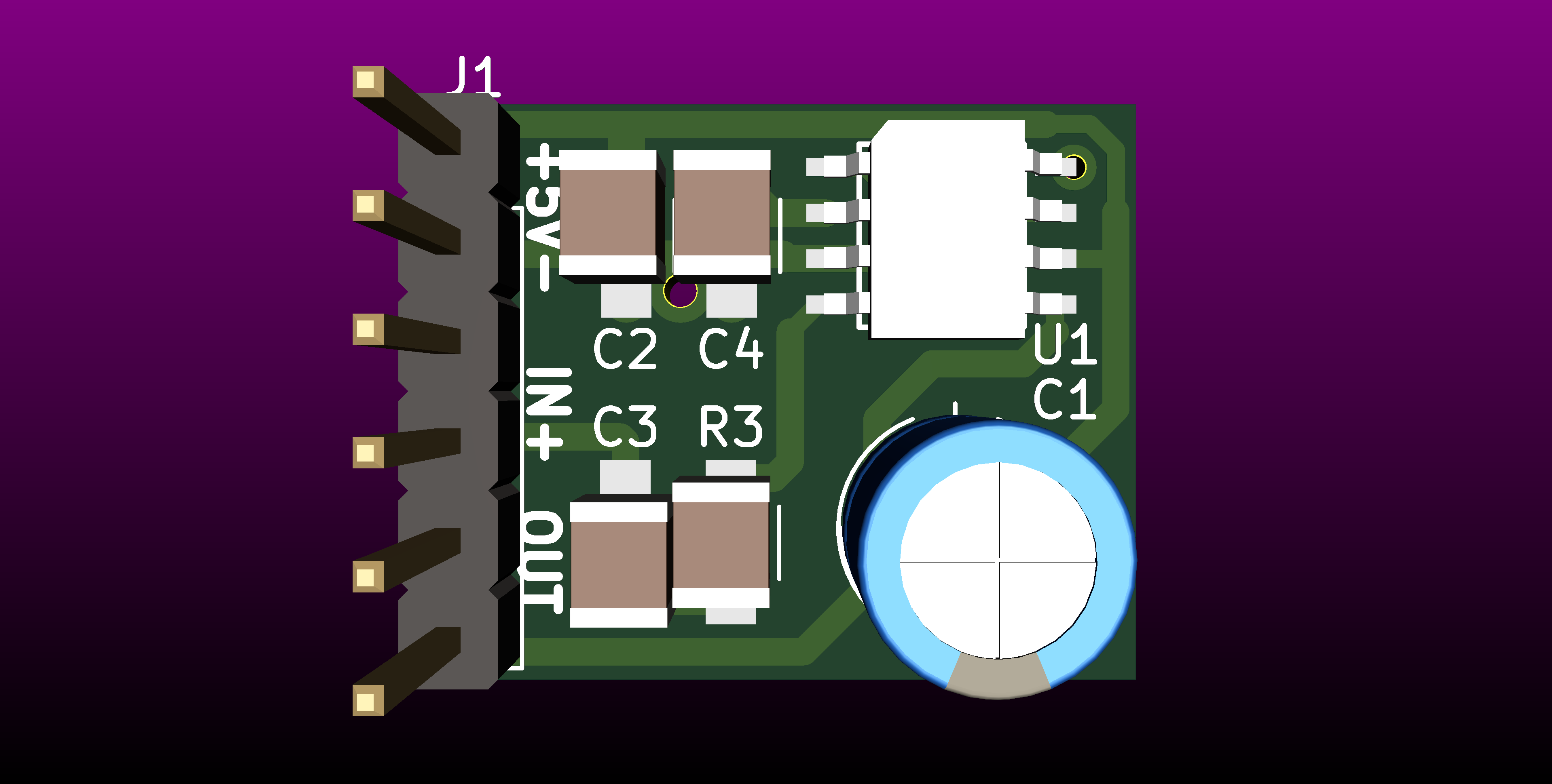
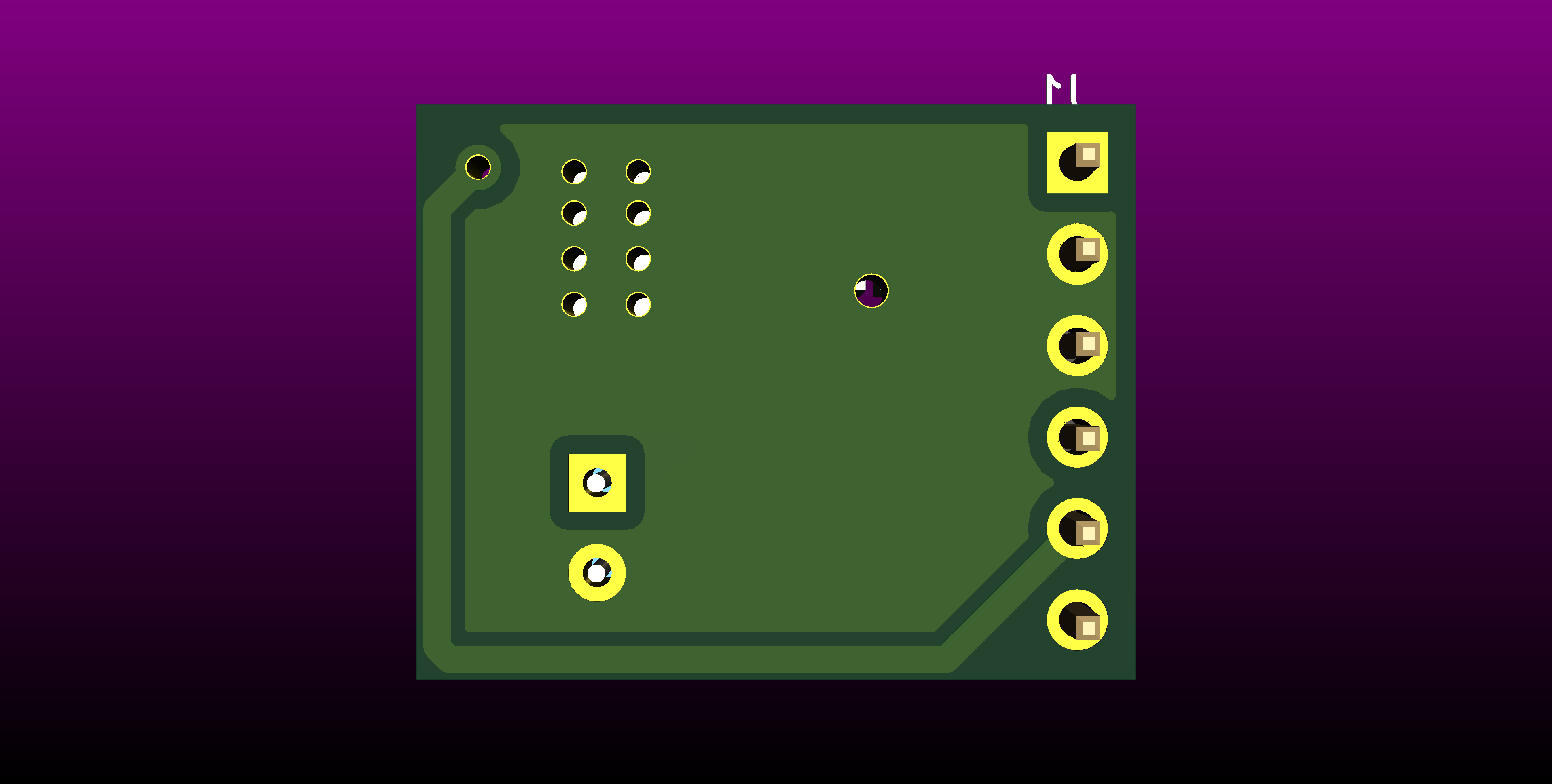 I haven't actually tried building this yet, so the current circuit just uses the commercially available version. At some point I need to order the XPT8871 amplifier chip so that I can test the version that made it onto the actual project PCB.
Discussions
Become a Hackaday.io Member
Create an account to leave a comment. Already have an account? Log In.