INTRODUCTION
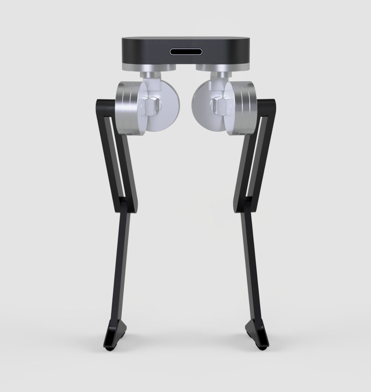
Blackbird is a new bipedal robot that specializes in high bandwidth force control and capable of meeting many of the expected demands for legged robots. As a result of its motor design, the robot can use virtual control models that allow it to replicate the compliant properties of springs, dampers, and torque sensing hardware without any extra costs (just math). The reduced mechanical complexity gives the robot a minimal design capable of high quality locomotion, perfect for research labs, college classrooms, and rapid prototyping in industry.
 DESIGN AND CONTROL
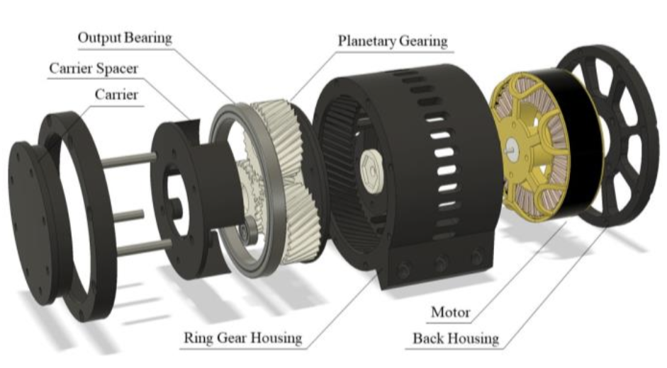
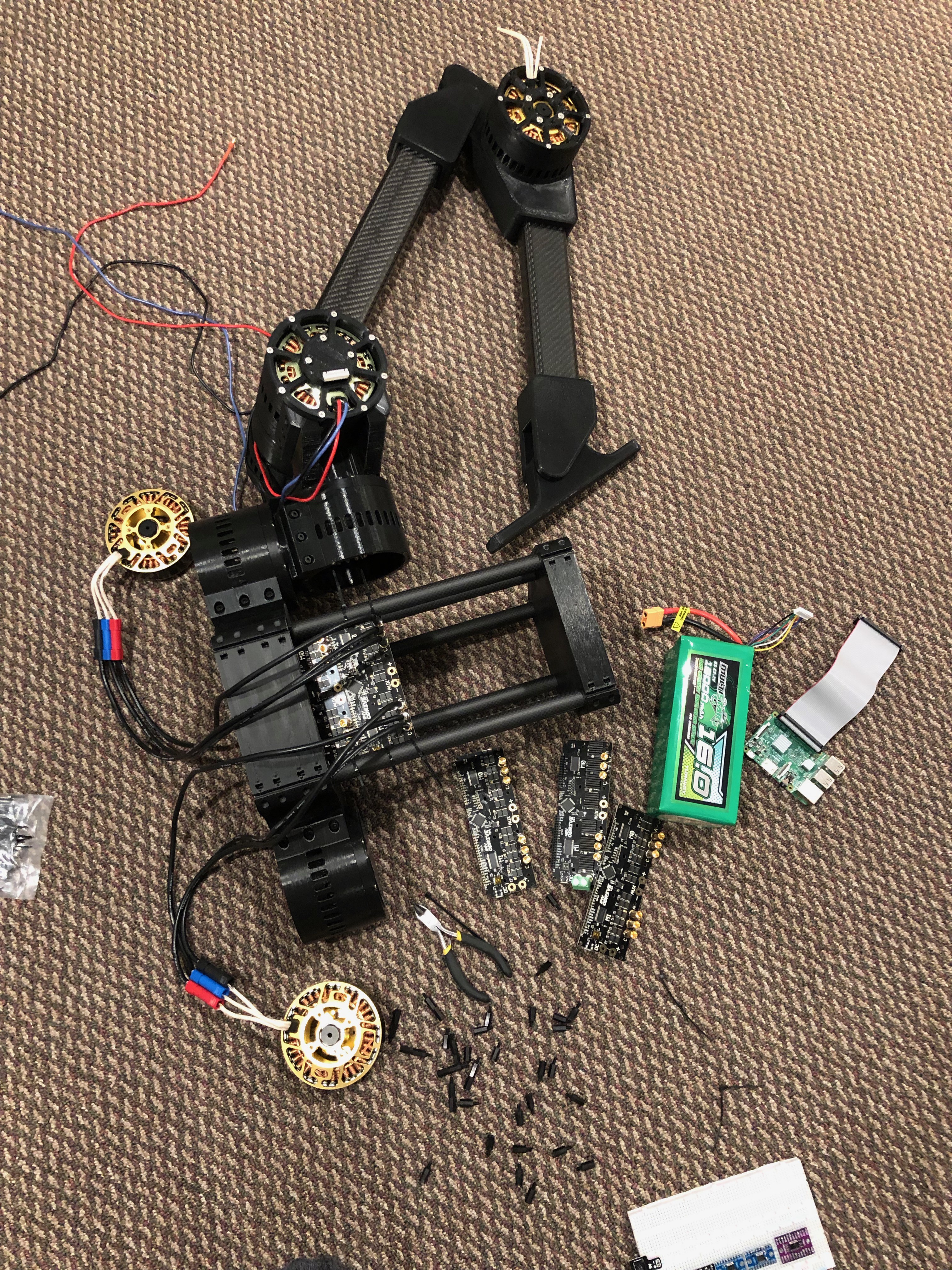
We designed the OpenTorque Actuator specifically for high torque scenarios that rely on high backdrivability; a key criteria for effective legged locomotion. Rather than relying on expensive sensors for measuring motor torque, the system relies on its quasi-direct-drive nature to create high resolution estimates of torque. This proprioception keeps the price of the actuator low, without sacrificing torque sensing capabilities, and also boosts the effective bandwidth of the actuator (allowing it to react faster).
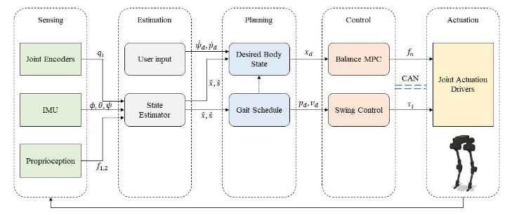
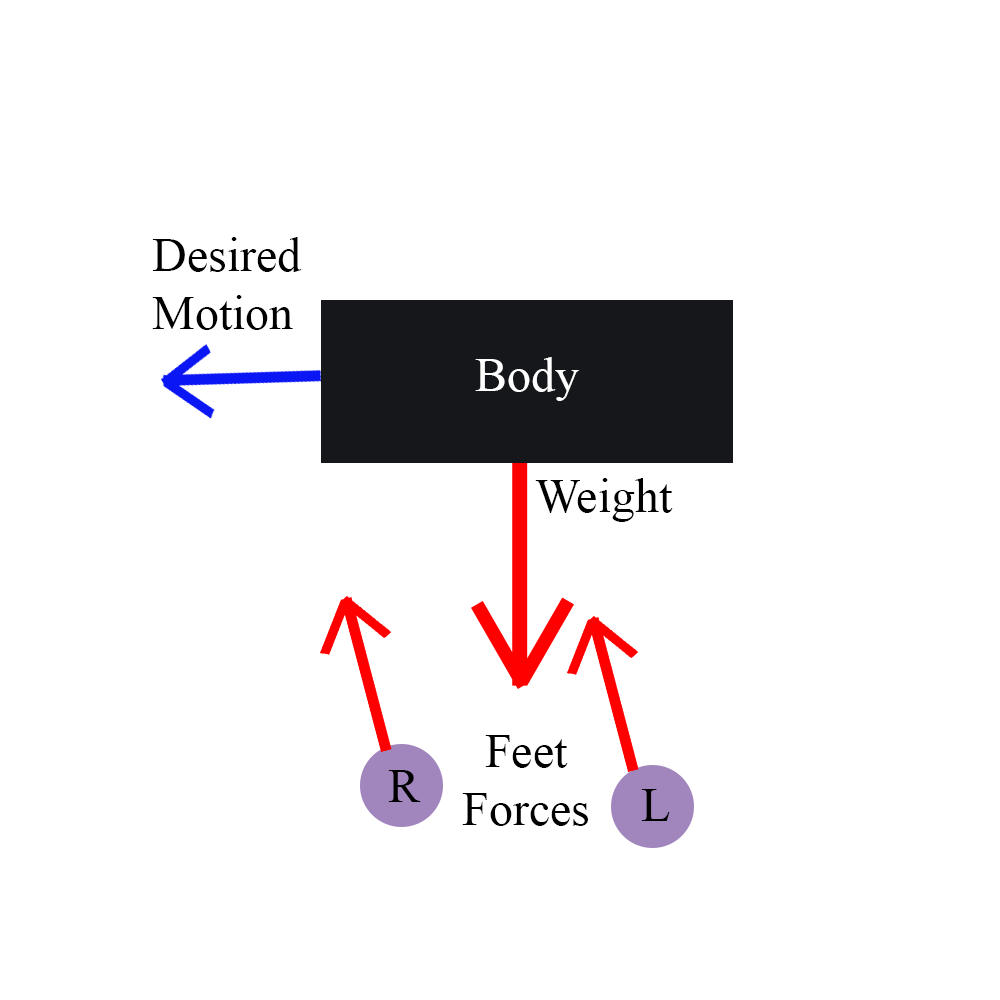
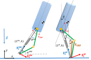
 Regarding the walking problem, we have developed two walking controllers for the robot. The first one is a reduced dynamics model based on the ATRIAS and CASSIE passive dynamics. Mathematically, this control method works well for environments with stairs and multiple unstable terrains. The second controller is a Model Predictive Controller (MPC) that can be used for more complicated maneuvers, such as jumping and walking while spinning. MPC relies on online optimization techniques to find the best force distribution that meets the desired user
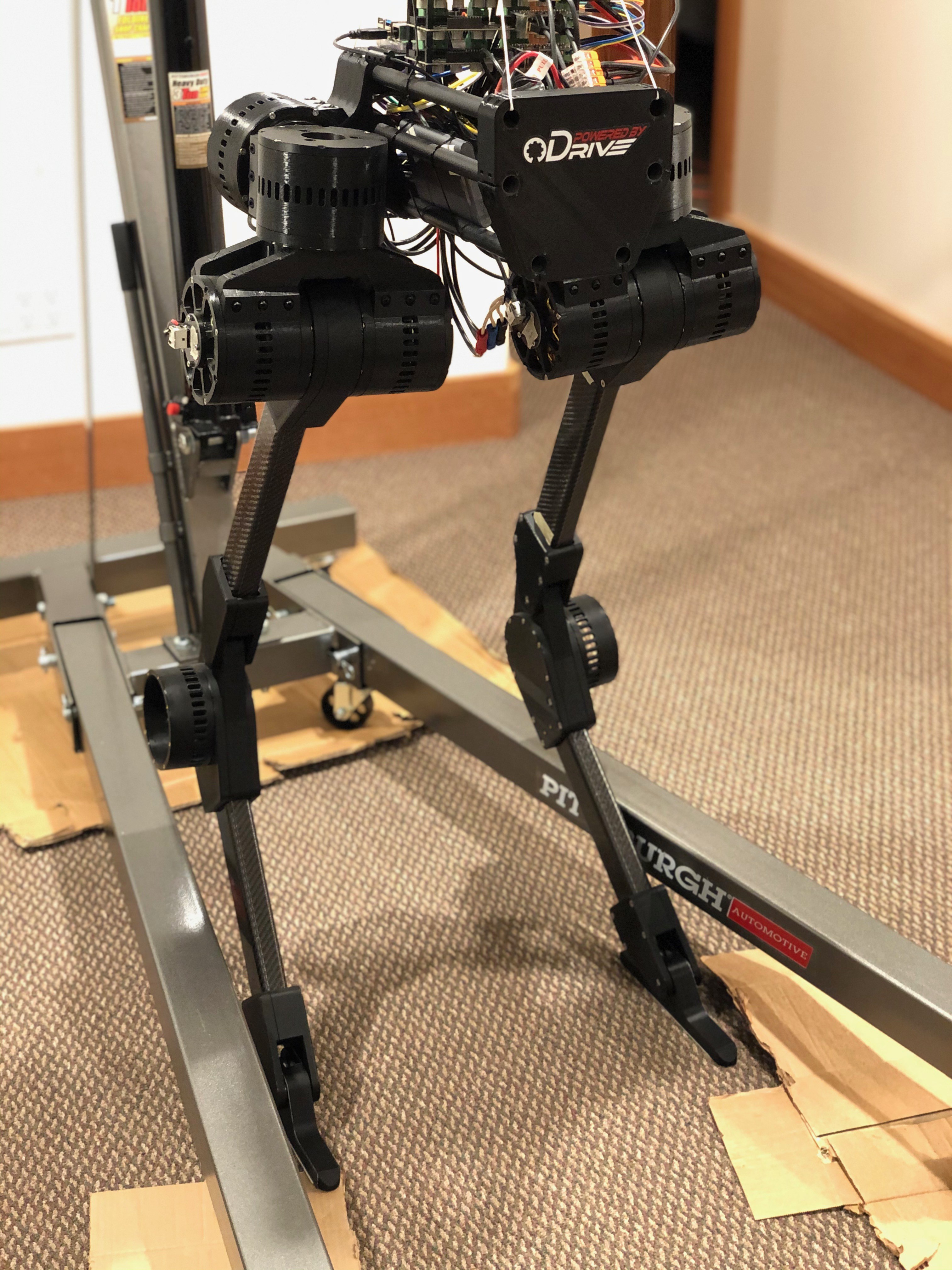
Blackbird stands 1.2 meters tall and weighs roughly 15 kg. Its estimated operation time is 2.5 hours with a 400 Wh battery. The total BoM cost is less than $3000, which is significantly less than any human sized bipedal robot capable of high quality force control. For reference, a single HEBI X-Series Actuator, which uses Series Elastic Technology, is about $3000 and is close to equivalent in force sensing capabilities.
TESTING AND VALIDATION
OpenTorque has a control bandwidth of approximately 30 Hz (3x-4x greater than that of a human) and is larger than many legged robots in the research community. For comparison, some of the best quadruped robots: ANYmal (SEA), HyQ (hydraulic), and StarlETH (SEA) actuators have maximum force control bandwidths of 60 Hz, 20 Hz, and 25 Hz respectively [higher is better] but are exclusive research tools and cost $X0,000+.
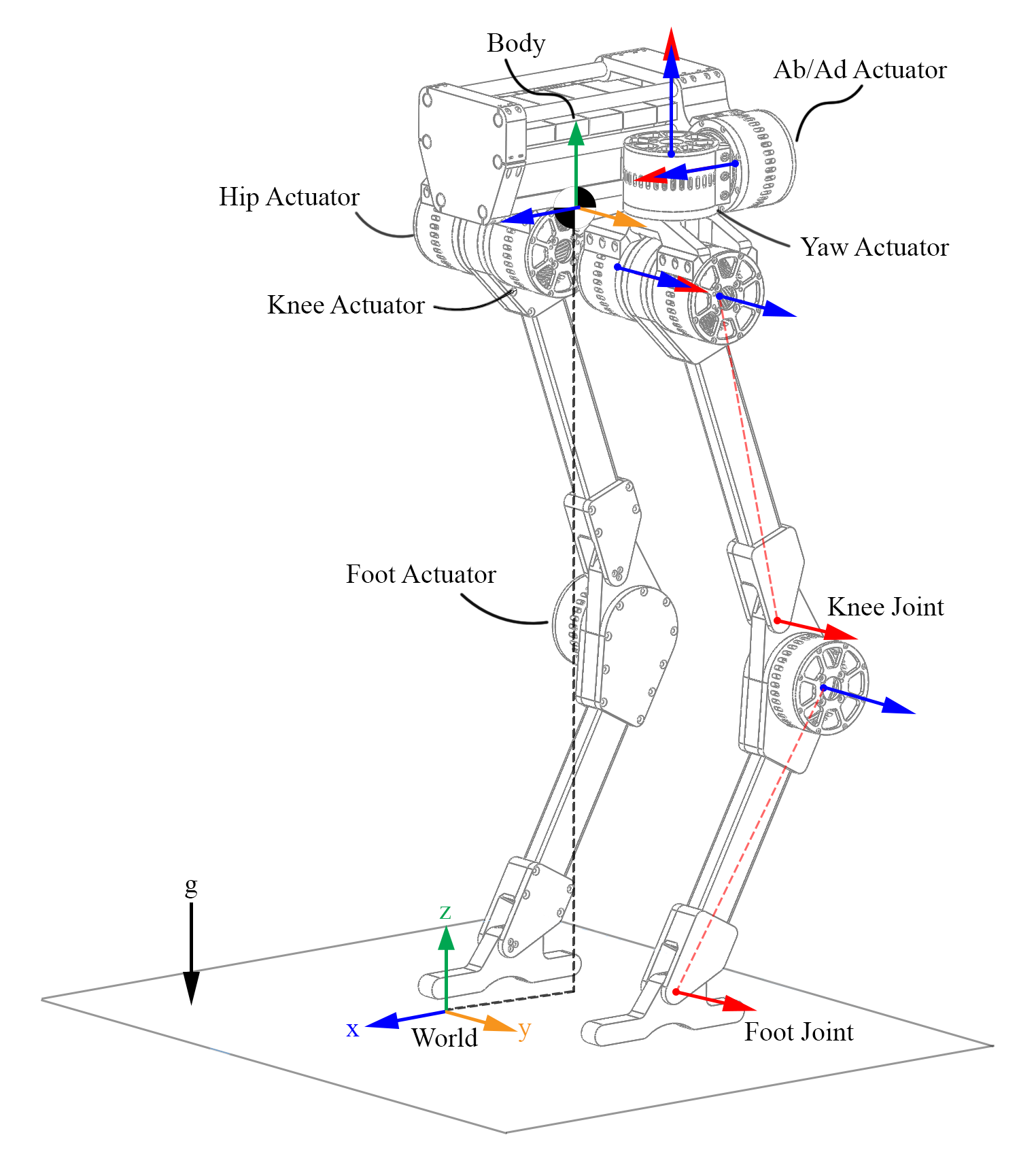
Each of Blackbird's legs has 5 Degrees of Freedom (DOF), totaling to 10 actuated DOF for walking. The system is capable of walking, running, spinning, and jumping as a direct result of the actuation hardware and control schemes used. We have also verified it's ability to operate in common human environments by executing maneuvers such as climbing stairs. Testing shows that the robot is capable of maintaining its balance even after receiving a 20 Pound (lbf) kick to the body.
PRODUCT NICHE
Since the robot is too inexpensive for industry settings, we hope that this platform can be used by students, researchers, and professionals interested in legged robot development to learn, test, and verify different control schemes or software stacks. We believe that hobbyists and researchers can hugely benefit from access to a low-cost, highly capable biped platform like the Blackbird, especially since there are no other bipedal robots on the market capable of equivalent force control per dollar. Locomotion is first and foremost a design and control problem long before it is a vision or AI based one. We hope that Blackbird helps bridge the locomotion gap by providing an effective platform for engineers and computer scientists.
We have also begun working Blackbird 2, which will use a new patent-pending motor design and more robust materials (injected molded plastic and aluminum) for a stronger frame...
Read more »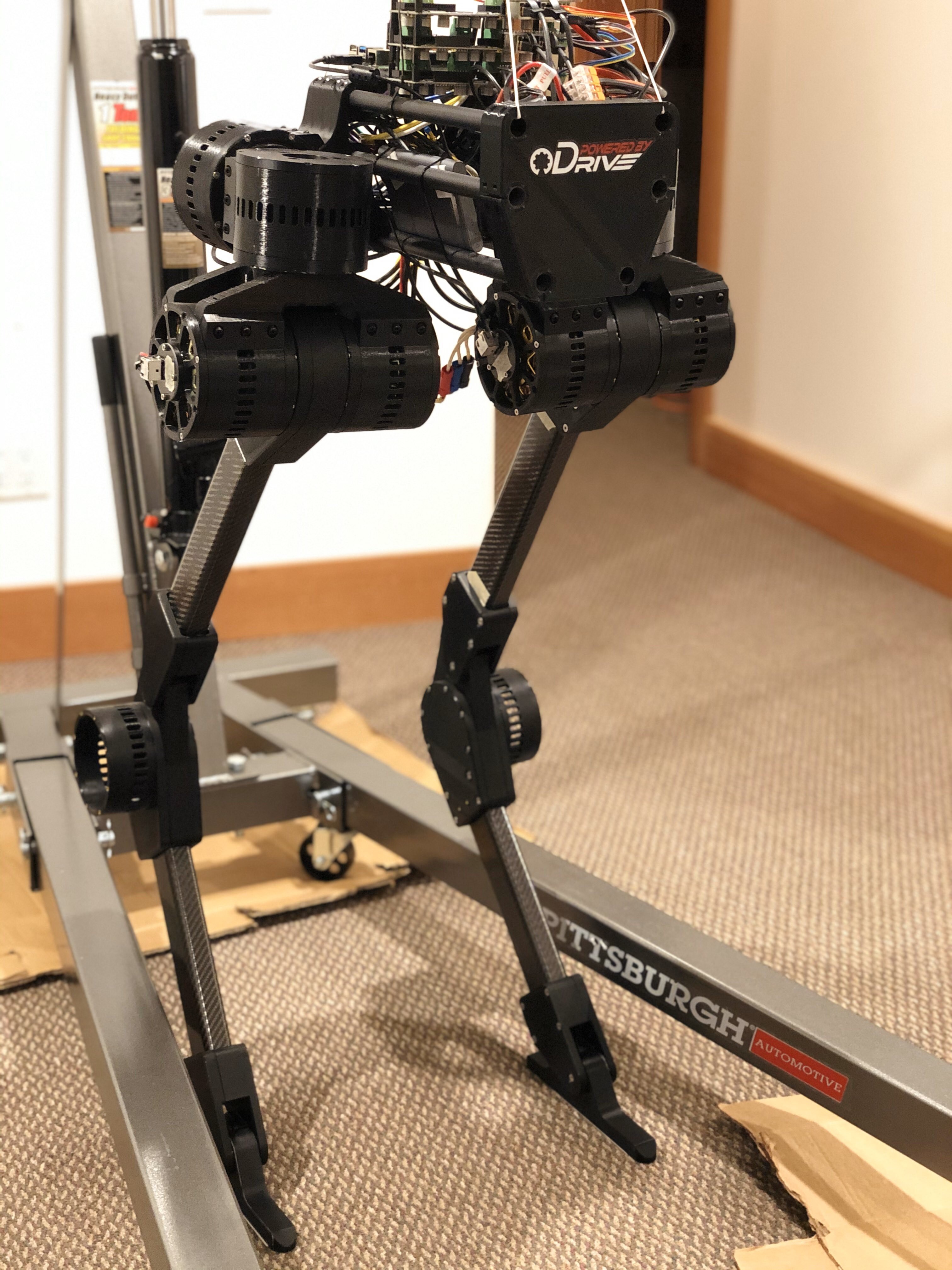

 For those that don't know cubic splines (red) have pretty bad position tracking if the distances between knots (X's). Our trajectories are getting calculated online based on the swing distance needed to walk at the desired speed, so cubic spline inaccuracies shouldn't be an issue because we can generate plenty of knots to interpolate during the swing trajectory.
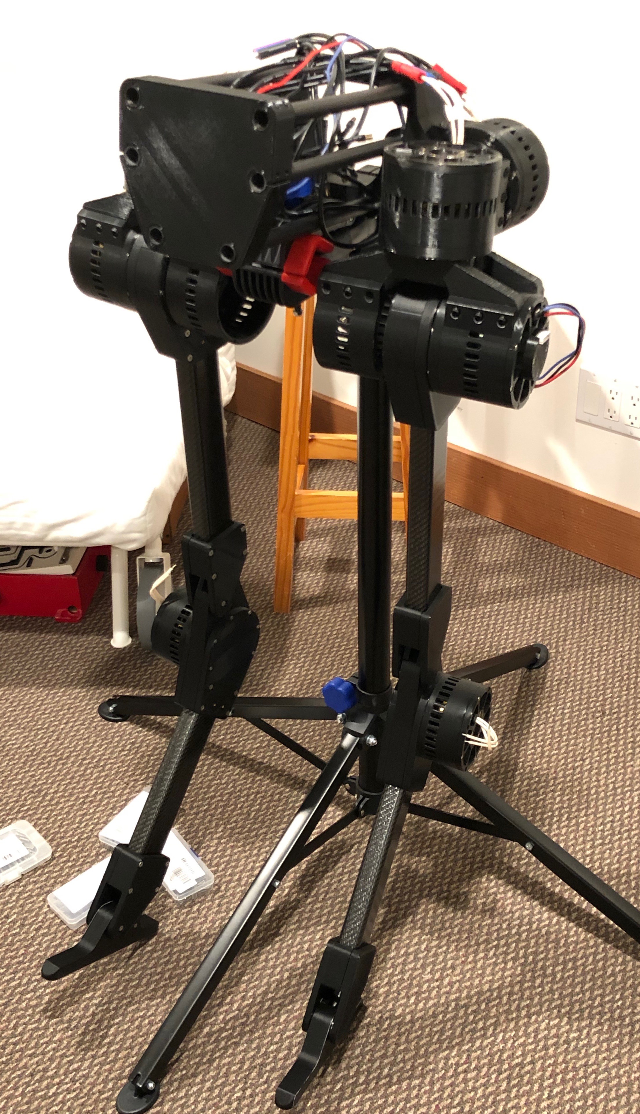


 VU Nhat Minh
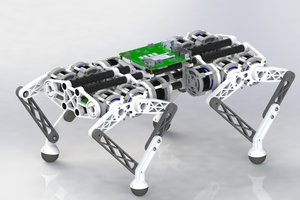
 pat92fr
 Open FURBY
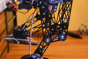
 Vipin M
If this project is OpenSource, where are the software sources? - because I was searching a lot and I could not found them. Thanks.