Close
0%
0%

GePS

standalone gesture controlled musical instrument

Public Chat
Similar projects worth following
Imagine you could use nothing but your hands to create sounds and music… like the conductor of an invisible electronic orchestra.

The Gesture-based Performance System (GePS) is an electronic instrument that lets you do just that! Through a small sensor worn on the wrist it captures motion data and transmits it to a raspberry pi-based standalone audio engine, where the movement is analysed and translated into sound. Hands are the ultimate interfaces and we all constantly use them to perform complex gestures in our daily live. That makes GePS very intuitive and natural to use. The accuracy of the sensors and the high transmission speed allows the capturing of tiny gestures, flicks with the fingers as well as big movements and strong impacts. This gives the performer a broad range of expression and a fine grained control over the sound. GePS is developed by the Swiss makers & sound artists Cedric Spindler and Frederic Robinson.

Imagine you could use nothing but your hands to create sounds and music… like the conductor of an invisible electronic orchestra.

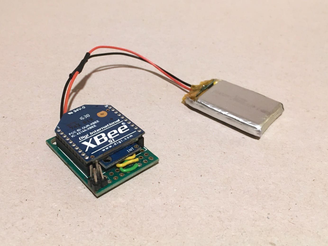
Through a small sensor worn on the wrist it captures motion data and transmits it to a computer, where the movement is analysed and translated into sound. Hands are the ultimate interfaces and we all constantly use them to perform complex gestures in our daily live. That makes GePS very intuitive and natural to use. GePS is an open source project, so anyone with a little Maker experience can assemble the sensor according to our hardware tutorials, download the code and setup their very own unit for free!

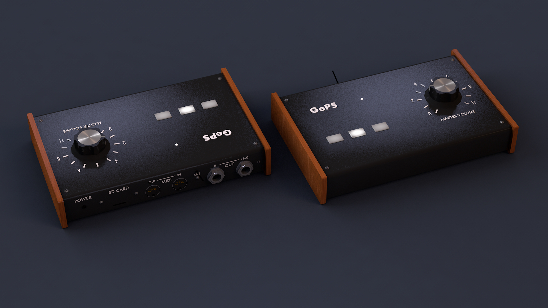
Our goal is to make GePS a standalone well-documented open-source electronic instrument, that is accessible to everyone.

The work with gestural interfaces on which GePS is based on has been presented in peer-reviewed publications and presented at conferences, fairs and concerts across the globe, including HopeX New York City 2015, 2016 Close Encounters Festival Tbilisi Georgia, 2015 International Conference on Music and Sonic Art (MuSA) in Karlsruhe Germany, 2015 Audio Mostly Conference on Interaction with Sound in Thessaloniki Greece. It was a semi-finalist at the 2015 Guthman Musical Instrument Competition at Georgia Tech.

GePS is developed by the Swiss artistic duo Cedric Spindler and Frederic Robinson.

Technology to enable Creative Freedom

The accuracy of the sensors and the high transmission speed allows the capturing of tiny gestures, flicks with the fingers as well as big movements and strong impacts. This gives the performer a wide range of expression and a fine grained control over the sound - resulting in great creative freedom.

Technical Details

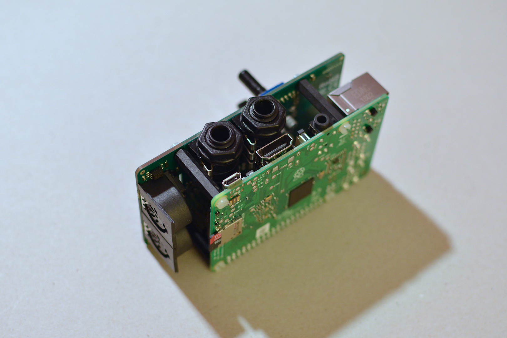
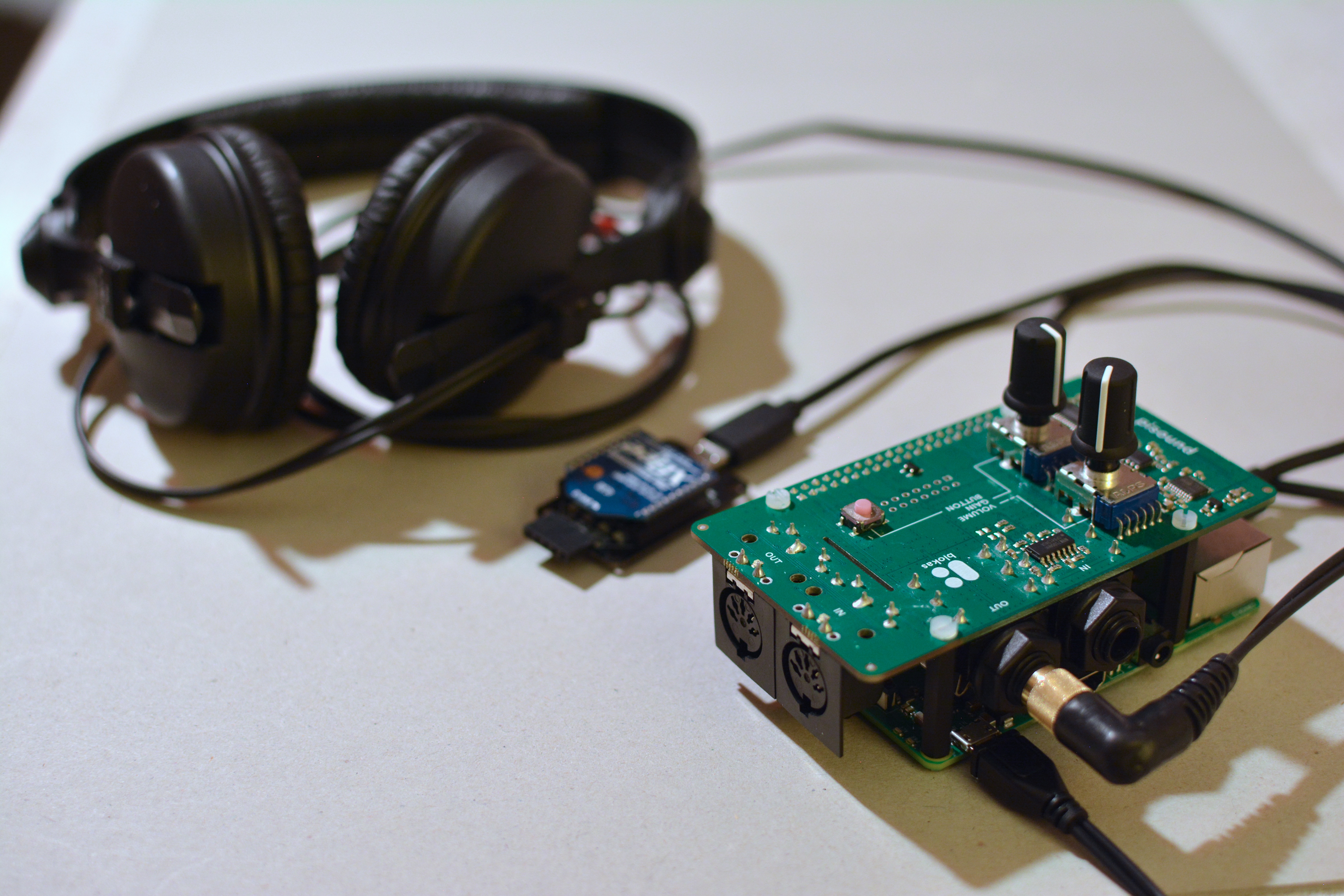
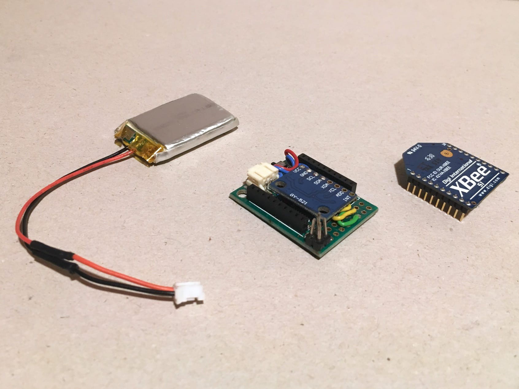
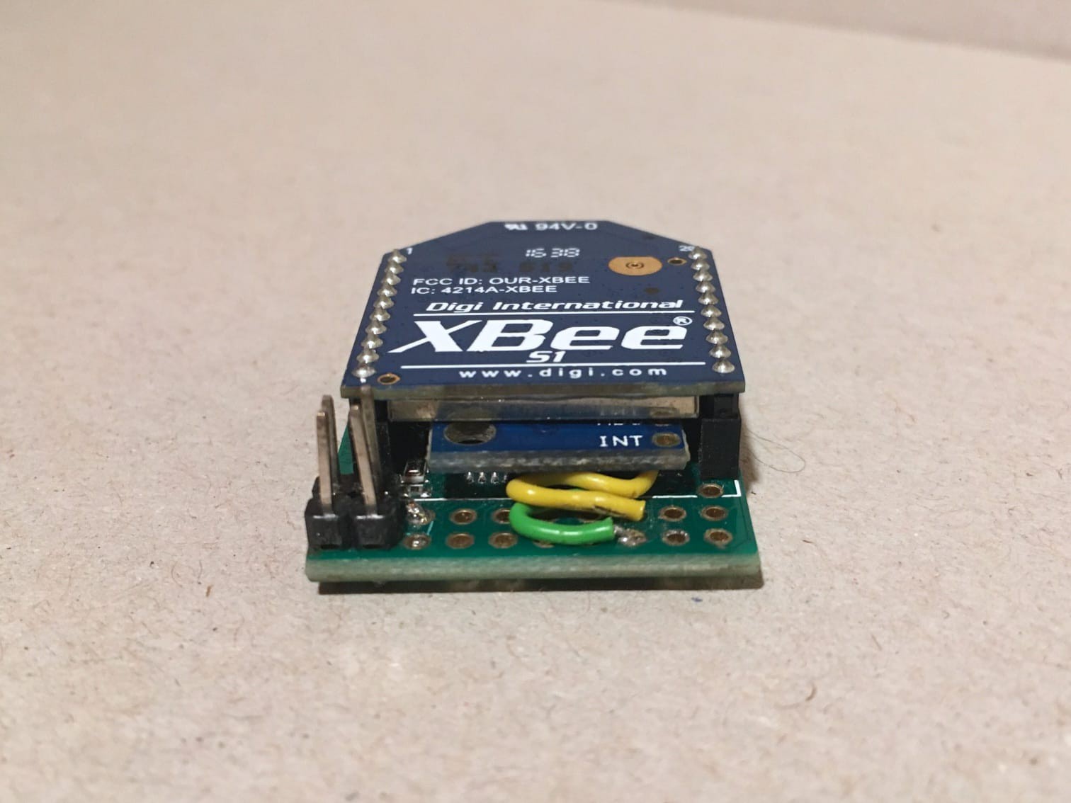
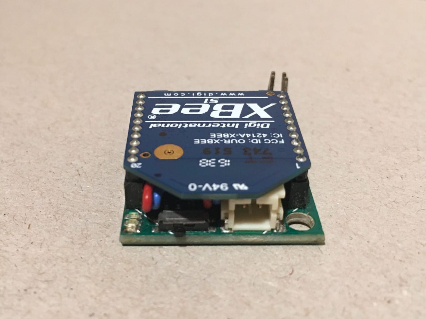
The performance system uses a 3 axis gyroscope and a 3 axis accelerometer as sensors, a tiny Arduino to read the data, a pair of XBee modules to transmit the data wirelessly to the software (pure data) running on a Raspberry Pi with a Pisound audio interface. The software consist of several custom built transformation algorithms and sound modules that are programmed and designed to the creative ideas of the performer.

2015_Robinson_Gestural-control-in-electronic-music-performance.pdf

Preprint PDF of our research paper about GePS and gesture metaphors. Published in proceedings of Audio Mostly http://dx.doi.org/10.1145/2814895.2814901

Adobe Portable Document Format - 280.13 kB - 10/07/2018 at 00:01

Preview
Download

illustration_009 - complete prototype in studio.jpg

Illustration: The complete GePS prototype as described in the project logs and build instructions, as we use it to practice performances.

JPEG Image - 4.21 MB - 10/21/2018 at 23:03

Preview
Download

GePS_case-3d-model.jpg

Our 3D sketch of what we'd like the case to look like

JPEG Image - 1.36 MB - 10/21/2018 at 23:11

Preview
Download

illustration_008 - complete prototype - sound module and glove sensor unit.jpg

Illustration: the GePS sound module and glove sensor unit

JPEG Image - 5.27 MB - 10/21/2018 at 23:03

Preview
Download

illustration_007 - prototype sound module in studio.jpg

Illustration with parts of our studio in the background

JPEG Image - 3.64 MB - 10/21/2018 at 23:03

Preview
Download

View all 12 files

  • 1 × DFRobot CurieNano A mini Genuino/Arduino 101 board featuring the Intel Curie module, including 6 dof IMU and 3 axis magnetometer
  • 1 × 2mm 10pin XBee Socket - SMD To connect the XBee (transmitter) to the Arduino Pro Mini
  • 1 × Pisound Audio Interface An ultra-low latency high-quality sound card and MIDI interface specially designed for the Raspberry Pi
  • 1 × microSD card Storage to hold the operating system of the Raspberry Pi and the GePS distribution. 4-8GB is comfortably enough space.
  • 1 × Power supply for Raspberry Pi Power supply providing 2.5A USB power to the Raspberry Pi (and Pisound / XBee)

View all 13 components

  • Happy Hacking!

    Zed Cat10/22/2018 at 13:02 0 comments

    The GePS sound module (GePS-MAIN.pd) is written in Pure data and features a modular structure, allowing you to extend the sonic capabilities by adding new submodules.

    GePS TRANSIENTS (geps.transients.pd): Plays percussive slices of an audio file by the flick of your finger. Depending on the intensity of the flick, different slices are selected. When increasing the amount of movement, a soft carpet of granulated impacts becomes audible.

    GePS FREEZER (geps.freezer.pd): This freezes and unfreezes whatever audio signal you send into it, by the flick of your finger. The frozen sound is played back at varying levels, depending on the intensity of your movement.

    Just recently, we implemented a Pure data external in C featuring the feedback network algorithm discussed in our research paper. Based on that external (fbnet~) we implemented a new GePS submodule, called GePS FBNETWORK (geps.fbnetwork.pd), featuring a network of resonating awesomeness! Wave your hand to agitate it, get it roaring!

    New GePS submodule: Feedback Network

    To get you started with developing your own modules, we prepared a template (GePS TEMPLATE, geps.mod-template.pd), that you can copy and modify. In itself it just plays back a sample when you flick a finger. But this was the starting point of all our modules. Let your creativity run free!

    The GePS submodule template

    Your very welcome to add your externals and modules as pull requests to the repositories (for externals, for modules). We'd love to see what you make of it!

    The structure of the GePS sound module is thoroughly documented on our website (including serial transmission, various patchers and abstractions). You can find instructions on how to treat the raw sensor signals and how to use this data to control you modules, how to structure your performance etc.

    We constantly work on this instrument for our own performances. You can expect more extensions to the sound modules to be added to the GePS repository over time!

  • Prototyping the sound module

    Zed Cat10/22/2018 at 12:07 0 comments

    Finding an audio interface

    The analog audio out (1/8 TRS socket) of the Raspberry Pi is not really useful for playing high quality audio, especially not if it should be amplified to higher sound pressure levels. One can hear a lot of noises caused by interference on this output, depending on how the Raspberry Pi is used. Over the last few years we tried out several interfaces, also USB connected ones, and we finally settled with using pisound by blokas.io with the Raspberry Pi. It provides super high quality, ultra low-latency sound in- and output and MIDI in- and output on top of that. All in a board plugged into the GPIO pin header strip of the Raspberry Pi and held in place by 4 insulating spacers. The pisound also features two potentiometers, one for input gain and one for output volume. It's a perfect match for our needs.

    Next generation prototype

    We worked tirelessly on getting the next generation prototype to run, and in the last week we finally completed it! And it's amazing! Find the build steps for detailed build and assembly instructions of the glove sensor unit and standalone sound module.

    We're very happy with the results :-) We see also see the next steps we'd like to take, for example in building a stage-proof case for the unit and further integrating the glove design, making it more solid and beautiful. Here's our 3D model of what the case could look like:

    Automating the installation process

    Usually a tedious, complicated installation procedure awaits you after copying the raspbian image to the Raspberry Pis SD card. But fear not! In order to simplify the installation process of the Raspberry Pi sound module, we put together an Ansible playbook for provisioning. In addition to that, we integrated the build process into a script, which in turn is also run by the Ansible playbook. Here's a list of all the tasks at hand, so you get an idea of what's being automated:

    Ansible Playbook

    • Upgrade raspbian
    • Install the software dependencies for building Pure data and dependencies/externals (gcc, automake, ALSA and FFT dev libraries, libtool and git)
    • Add the pisound package repository
    • Install the pisound packages
    • Disable unnecessary services (pisound-ctl, pisound-btn), as they consume a lot of resources at times
    • Configure the default sound card (pisound)
    • (running the build script, see below)
    • Enable starting the GePS sound module (with a systemd system unit) when booting the Raspberry Pi

    The build script

    Building Pure data and dependencies from sources, install the GePS package

    Finally the GePS package is cloned from github

    You may hack away on your Raspberry Pi sound module, and whenever you think it's all in pieces, just run the playbook again to get back to the roots!

    Happy hacking!

  • Transmission Error Correction

    Zed Cat10/20/2018 at 15:26 0 comments

    While achieving great results with our efforts to reduce latency between sensor and sound module we noticed a little problem: At higher baud rates than 38400 baud the connection (radio transmission) becomes slightly unstable at times, resulting in dropped bytes. The serial bytes parser in the sound module doesn't like that very much, as it messes up the sequencing of the sensor data. You may notice byte drops as very narrow peaks in the sensor data plot.

    To counter this we implemented a watchdog that notices when an unexpected value appears in the place where we usually see the sequencing byte pair (255 255, or 65535 expressed as a sensor reading). The watchdog will reset the sequence to latch onto the next sequencing byte pair, and will repeat that every second until the flow of sensor data is correct again.

    You can find the corresponding commit in the GitHub repository (commit 8d2a166a).

    A note on data sequencing

    To transmit the sensor data with maximum resolution but least amount of overhead (no axis labels), we chose to define a sequencing byte pair that the receiver (the sound module) can uniquely identify as the start of the next sensor reading. To make the least compromise on sensor reading, we limit the resolution of each axis to 2^16-1 values. The range of values starts at zero, therefore the highest value a reading will show is 65534. The value 65535 is reserved as the sequencing byte pair (as this value gets split up into 2 bytes, each of value 255).

    While splitting the high resolution values into bytes for serial transmission we still have to take care that the last byte of one axis value (LSB, least significant byte) and the first byte of the next axis value (MSB, most significant byte) do not combine to the sequencing byte pair. This looks like a rare case, but at that data rate even this becomes frequent, especially when performing. So if we encounter such a case, we subtract 1 from the LSB in question (check out the file arduino/sensor_data_tx/sensor_data_tx.ino for implementation details).

    If you pay close attention you may ask yourself "what about the case of a sequencing byte pair + 255 of the following axis first byte"? This is a good question, but it's not a problem: On the receiving end the parser matches the first two bytes of value 255 and the following one will be interpreted correctly as what it is.

    The only case this could break is when the first byte of the sequencing pair gets lost in transmission. Furthermore, if bytes get lost on the way to the receiver, the counting of the sequence gets out of order, and we can't properly parse the data anymore. But since this update: fear no more! The byte stream is being watched by the sharp eyes of our watchdog and hickups are quickly dealt with.

  • We're excited!

    Zed Cat10/20/2018 at 14:13 0 comments

    We're tirelessly working on our project, and we're making progress! The project logs and build instructions are going to be updated very soon.

    But first! We're very happy to share with you that we are among the finalists of the Musical Instrument Challenge of the 2018 Hackaday Prize. Yay! We keep you posted.

  • Sensor Hardware Integration

    Zed Cat10/07/2018 at 16:47 0 comments

    Goals

    The first issue we attack is the integration of the sensor unit:

    • Better form factor for easier wearability. It should be possible to sew the unit into the glove.
    • Bring down latency: Lower latency for better performance experience through improved fusion of movement and sound
    • Add a switch to turn it on and off

    So far we had good results with using the custom Arduino design described in the last project log. But the bottleneck is at the clock rate of the MCU: It runs at 12 MHz and with all optimisations this gets us to a latency of ~4.5ms. This is already pretty good. But performing many concerts with this instrument showed us that the whole experience will benefit from decreased latency, even if it's only 2 or 3ms.

    If you transmit the sensor data through wired serial connection, you can experience the difference, as latency drops to ~3.2ms. But who wants to perform with strings attached?! :o)

    The first step we took is to replace the XBee Explorer Dongle by the DFRobot XBee USB Adapter V2 to hook up the XBee to the computer. This adapter features the Atmega8U2, allowing a faster and more reliable connection. Only by replacing this adapter we already gained 1.5ms!

    XBee USB Adapter
    XBee USB Adapter V2 - Atmega8U2 with the XBee attached, receiving sensor data

    Finding a new platform

    The real issue is clock speed and the corresponding possible baud rate through wireless transmission. Coming from the Arduino Pro Mini (8 MHz, ~6ms, 38'400 baud) to the Sense/Stage Arduino (12 MHz, 4.5ms, still 38'400 baud) led us to increasing both clock speed and baud rate. The third parameter that could be an obstacle is the sensor sampling rate.

    More recent Arduino boards show great specs but when it comes to the form factor, they disqualify. But one module showed amazing specs: The DFRobot Cure Nano.

    • 32 MHz Clock Speed
    • IMU (Sensor) integrated into the chip package
    • Gyroscopes can be sampled at up to 3.2 MHz! The accelerometers at up to 1.6 MHz.
    • runs at 3.3V with options for 5V
    • secondary hardware serial port for connecting the XBee
    • 23.5 x 48 x 5 mm.

    Fantastic!

    The only drawbacks to the Sense/Stage: There are no integrated XBee headers and no power switch. The missing XBee headers we use as an opportunity to move the antenna to an other position on the glove. By that we achieve better radiation characteristics (in other words: we reduce shielding the radiation by the hand or body of the performer). The power switch we also sew to the glove (for the prototype we go with the Adafruit switched battery connector "JST-PH").

    If you want to add another 3 degrees of freedom: The Curie Nano even features a 3 axis magnetometer (compass)! That would allow to determine absolute direction during performance (i.e. for events where you point a objects on stage / in the room).

    The new unit, before assembly
    Cure Nano, XBee headers, Xbee, power switch and LiPo battery

    Reprogramming the sensor

    We update the sensor unit code to run on the Curie Nano. This includes the following changes:

    • Add include for the CurieIMU library (reference, install in Arduino IDE)
    • Drop I2Cdev code (The I2Cdev library is included with the CurieIMU library)
    • Replace the sensor library: We say good bye to the MPU6050 and welcome the BMI160.
    • Change datatype of axis variables. This becomes necessary because the wrapper for the I2Cdev library defines other datatypes.
    • Drop the XBee setup / transmission code. We use the hardware serial port of the Curie Nano
    • Set accelerometer and gyroscope ranges and sampling rates

    Great! With these changes alone we drop to a latency of 3.2ms!!

    Increasing baud rate

    The baud rate has to be changed in the settings of both XBees, the sensor unit code and testing sound module!

    Increasing the baud rate delivered great latency improvements: at 115'200 baud we reached a latency of 1.3ms! But sadly the XBee connection became unstable (bytes got dropped frequently) to a degree that is not acceptable for performing on stage. Waiting...

    Read more »

  • Better integration

    Zed Cat10/06/2018 at 23:37 0 comments

    In order to better integrate the sensor unit we tried a few approaches. The best results by far we got using the custom Arduino design (Minibee) by Marije Baalman in her Sense/Stage project:

    We soldered the MPU6050 breakout board to the Arduino board. By placing it neatly between the XBee headers, the sensor is being kept in place after plugging in the XBee module. The Sensor is "sandwiched" between Arduino and XBee.

    Connect to the glove

    With this design plus a little bit of sewing it was possible to create a comfortable wearable instrument. We also got rid of the 3D printed case. Shrinking the whole sensor unit to around half the original size allowed placing the electronics inside the glove, firmly attached in order to capture the gestures with best accuracy.

  • Preparations

    Zed Cat10/06/2018 at 20:58 0 comments

    Updating to Pure Data (Pd) vanilla

    In preparation for the reinvented version - let's call it GePS 2.0 - we moved the sound modules implementation away from Pd-extended to Pd vanilla. Pd-extended has been abandoned a while ago. Miller Puckette and a nice community of artists and developers at github keep Pure data growing and updated. We can not recommend enough to dig into this fantastic piece of software and the ecosystem based on it (i.e. libpd)!

    The modules still depend on some third party libraries, but since the recently released version of Pd (0.48), the deken plugin for installing third-party libraries is now included in the standard distribution. Thanks to this plugin it's very easy to install the dependencies:

    • cyclone
    • list-abs
    • freeverb~

    The changes (tagged v4.2) for the update to Pd 0.48 have been already implemented into the codebase and published to the repository. After installing the dependencies you're good to go! Be sure to check if the configured serial port is the one available on your system.

    Changelog

    - Version 4.2, update for Pd-0.48 vanilla compatibility (24f5b79f)
    - Refactor the serialport code (2ca4ab6c, d9218c7c, 0b0971a1)

  • The beginning of a new chapter

    Zed Cat10/06/2018 at 20:34 0 comments

    Building on the developments and research of our project "GePS - Gesture-based Performance System" (github, homepage) we are taking on reinventing the instrument. At the core, there are some key issues that we address:

    • Better form factor for easier wearability
    • Lower latency for better performance experience through improved fusion of movement and sound
    • Standalone sound module to be able to play the instrument without a laptop or workstation connected.

    Furthermore we aim for better hackability through more programming interfaces and updated documentation as well as new and exciting sound modules and content.

    We will publish a new repository for the next chapter in the history of GePS. The legacy version will be kept available and working in the current repository, by back porting compatible changes from the new version.

    Current Instructions & Documentation

    We host the build instructions, research and documentation for the current (legacy) version of GePS on our homepage at http://geps.synack.ch. Here's a map to get you to the right information quickly:

View all 8 project logs

  • 1
    Get prepared

    Get prepared by checking that you have all the required parts ready. 

    Parts

    Tools

    • Soldering iron
    • Solder
    • Pliers (for electronics)
    • Scissors
    • Needle for sewing
    • Insulation tape
    • Marker pen
    • Ethernet cable

    Software

  • 2
    Load the code to the sensor unit

    Before soldering anything to the CurieNano, we test if the setup works.

    Open the Arduino sketch from the repository arduino/sensor_data_tx/sensor_data_tx.ino and modify it for testing. We want to transmit the sensor data through the USB connection. For that to work, all references to the Serial1 instance have to be changed to Serial (drop the 1), which corresponds to the serial port at the USB interface.

    Now the Arduino IDE needs to know how to communicate and program the CurieNano: In the Tools Menu select the following options

    • Select Board: Aruino/Genuino 101 (the one you installed in the preparation step)
    • Select Serial Port: dev/cu.usbmodem1421 (the numbers in place of 1421 may vary)
    • Select Programmer: AVRISP mkII

    That's it. Verify and upload the sketch to the CurieNano.

    Open the PureData sound module for testing (pd/GePS-MAIN.pd in the repository)

    Open "serial settings" in the CONTROLS panel. Check if the Pure Data patcher will connect to correct serial port. You can get a list of available ports by click on the "ports" button. Enter the correct port number where indicated in the comment.

    Use the open/reset button in the SERIAL-STATUS panel of the MAIN patcher to connect. View the parsed sensor data by clicking "plot sensor data". Move the unit and observe the plots.

    If this works, proceed and undo the changes in the Arduino sketch. We want to connect to the XBee as soon as it is soldered to the CurieNano. Upload the sketch (you won't see any sensor data in PureData anymore).

  • 3
    Configure the XBees

    Prepare

    • Label the XBees with tape and marker pen, one "TX" and the other "RX"
    • Plug the "TX" into the XBee USB adapter and connect it to your computer.

    Depending on the serial terminal client you use, the connection procedure may vary. In this instruction we will use "minicom", installed with your favourite package manager on your favourite operating system.

    Minicom connection instructions

    In your favourite terminal emulator enter the following command (The baud rate of 9600 is the XBee default rate, it will change to 115200 after successful configuration below).

    minicom -D /dev/cu.usbmodem1421 -b 9600

    Use these commands to control your session:

    • Ctrl-A A or Meta-A* to add linefeed
    • Ctrl-A E or Meta-E* to turn local echo on
    • type the AT-commands IMPORTANT: the XBee is in programming mode only until 10s after establishing the connection. So hurry up or disconnect/reconnect.
    • Ctrl-A X or Meta-X* to exit and reset

    * In Mac OS X, the Meta-key is "Esc".

    For more information / options on Linux/Unix read this article: 5 Linux / Unix Commands For Connecting To The Serial Console.

    Configuration

    • With the connection open, type the commands as shown in the table "XBee configuration commands" below, using the command parameters for the TX unit.
    • Close the connection and unplug the dongle. Swap the TX unit with the RX unit and connect it again.
    • Open the connection in CoolTerm and type the commands as shown in the table below, now using the command parameters for the RX unit.
    • Close the connection and unplug the dongle. You can leave the RX unit plugged into the dongle, as it will be used like this later on.

    XBee configuration commands, step by step

    Command TX RX Comment
    +++ Enter XBee programming mode. Don't press return, but wait until the XBee responds with OK. All following commands will be sent by pressing return.


    ATREReset configuration of XBee.
    ATMY21Set local ID.
    ATDL12Set ID of unit to connect to.
    ATID11151115PAN ID (Personnel Area Network ID) value can be anything from 0000 to FFFF. Two units communicating with each other need to have this set to the same value.
    ATBD77Baud rate, this value need to be the same on both XBee modules, so they can talk to each other. You need to choose a baud rate of 115200 once you reestablish the serial connection in order to program / communicate with the XBee.
    ATCH0E0ESet channel. This can be any HEX value between 00 and 1A. 0E is an example. If you use multiple units (GePS) at the same time, make sure they use different channels.
    ATWRWrite configuration to XBee memory.

    Refer to the XBee Command Reference Tables if you need detailed information on the AT commands.

    The channel ID is superior to the PAN ID, if you use multiple units (GePS), they can use the same PAN ID, but not the same channel ID.

    The XBees are ready to establish communication between sensor unit and sound module!

View all 7 instructions

Enjoy this project?

Share

Discussions

Similar Projects

Does this project spark your interest?

Become a member to follow this project and never miss any updates