 Thomas
I found a new example of circuit bending grade electronics engineering in my postbox: the XH-M188. It's advertised as "XH-M188 numerical control voltage regulation module" and it's rated "0-12V 1.5A 18W", and last time I checked there was exactly nothing on Google about this cheap board. Now there is ;-) 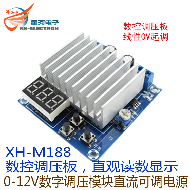
As expected the board has a STM8S003F3 µC - there was no way to know that for sure, but call it gut-feeling ;-). The PD1/SWIM on the ICP interface is free, but all other GPIOs are all used for either 7S-LED, keys, or the "numerical control" (and one seems to be unconnected).
I did a quick check. Here are the fun facts:
- the "numerical control" is just a 4.5 kHz PWM signal with duty cycle setting through "+" and "-" key
- the control part is indeed analog (LM358 with a TIP142)
- the display value represents "duty cycle * X". There is no feedback whatsoever.
- the output voltage can be adjusted with the help of a trimmer potentiometer
- the LED multiplex clock is about 16xPWM cycles
Due to a bug in the PMW code, every 16th cycle is only about half. This obviously leads to an analog ripple with about 280 Hz, and more importantly to an offset (which can't be compensated with a trimmer). However, the resulting inaccuracy doesn't really matter since the "voltage reference" is a trusty LM7805.
The maximum output voltage seems to be 11.4 V (at the rated supply voltage of 15 V). The accuracy drops considerable from just below 11V.
All this doesn't mean that the board is good for nothing. At $4.75 it's not exactly an expensive piece of lab equipment for home-brew test automation, and I had planned to write half-duplex Rx/Tx synchronous bus protocol code for a GPIO with interrupt before ;-)
Edit:
- a preliminary µC pin connection list is in the project GitHub Wiki
- as expected, the ratio of display value to PWM duty-cycle appears to be constant
- I forgot to mention that the 7S-LED display is socketed. When you remove it 11 GPIO can be used without soldering
Discussions
Become a Hackaday.io Member
Create an account to leave a comment. Already have an account? Log In.
@Elliot Williams' code is in the v2.2.11 release, and there are updated board docs in the Wiki:
https://github.com/TG9541/stm8ef/wiki/Board-XH-M188
Are you sure? yes | no
I am extending the BAREBONES option in STM8EF to exclude as much code as can be from the flash, and providing Forth code for all the removed items. I've got it in a fork of STMEF on GitHub (https://github.com/RigTig/stm8ef). I have found a couple of issues in the process, but progress is being made. My intention is then to cherry pick the code I need, thus freeing up valuable NVM space for application code. Perhaps this might help you too. And, yes, I am sure to need PWM words. And probably lots of others. All contributions welcome.
Are you sure? yes | no
Hi Elliot,
great to hear that you take the lead in supporting this board!
I guess that removing the LED display is a good decision (operating a serial console through the key inputs might also work, but using TxD (PD5) and RxD (PD6) is a good option.
As for the PWM code: the intended workflow for board support is the following:
* fork STM8EF
* copy a suitable board support folder (e.g. MINDEV, add PWM code from DCDC)
* in boardcore.inc, add additional initialization to BOARDINIT:, and add or modify I/O words
* test, and do a pull-request
To date, PWM words have been treated as an add-on (the CN2596 code in the DCDC board support folder is an example).There is a work item in https://github.com/TG9541/stm8ef/projects/1 , and there is a cheap "2 PWM Board" on my ToDo-list, too. However,
under the impression of the work done by @RigTig I now thing that it's better to keep the core code small, and to use a modular approach.
Alternatively, you can use a minimal configuration, and code board support in Forth (e.g. NVM : start ( do stuff ) ; ' mystart 'BOOT ! RAM ), but that also requires a build system for board support that can compile Forth code. That's on my list, but I need to lay the groundwork first.
Are you sure? yes | no
I wasn't looking for code examples in DCDC. That helps a lot, and makes it clear where the board-specific words should go as well.
I also just now noticed that you used a different PWM pin than I have to. You're lucky -- you sidestepped the whole "alternate function" thing.
I'm also not so interested in supporting the LED screen on this one directly. Is it cool if I leave that stuff out and just get voltage control over serial working well?
Are you sure? yes | no
Using the LED header as a GPIO pin breakout is a good option for a remote controlled power supply. The stunt that brings a serial console to a CN2596 segment driver pin requires "common cathode" (and some hardware nasties).
The XH-M188 has "common anode" which would at least require a transistor as an inverter to make it work together with the LED display.
Just curious: how do you change the alternate functions bit (i.e. in the startup routine, or using an ICP programmer)?
Are you sure? yes | no
In the startup. You have to do the eeprom lock, then a pair of bits to allow you to write to "option eeprom", then finally flip the alternate function bits, and then unroll the above.
It's probably cleaner to do with the programmer, but I didn't look into that option. Doing it in the board init keeps your build routines cleaner too.
I'll submit a quick pull now, but I still need to get the buttons working like the other boards before calling it "finished".
Are you sure? yes | no
IMO using the IAP feature is a clean and streamlined option. I just pulled the changes & I'll give them a quick test on my M188 later on.
Are you sure? yes | no
Hi Elliot, thanks for the pull request! Currently you don't appear as "", which may be due to the following: 1) you have to be a "collaborator" (invite sent), 2) the email address you used in your commit doesn't match the one in your profile. For details check https://help.github.com/articles/why-are-my-contributions-not-showing-up-on-my-profile/
The GitHub Wiki contains a XH-M188 page. I guess that we should define a feature set (e.g. no LED display but "GPIO breakout" instead), and update the Wiki accordingly.
Are you sure? yes | no
Hi Thomas,
Bought one of these just for fun, and can confirm the glitch that requires a pullup resistor on the NRST line to make it program correctly. I can also confirm that it works fine with your Forth -- getting the hardware PWM working was a PITA, however because of the "alternate function" bit in option memory. Finally got it working, though.
The real advantage of this board is that so many of the GPIO pins are freed by simply unplugging the LED display -- and there are three buttons built in to boot. Aside from the resistor, connecting the programmer is also very straightforward.
Right now I have everything loaded up, but I'll be trimming the Forth build down to just what I need on the device. I'll submit a pull request when I do.
How do you like to deal with support code? For instance, some extra bit-flipping is needed to initialize the PWM for voltage control. Where should those go? They could be re-written in assembly and added to the core (and optionally compiled), or they could just be left in Forth to accompany the board. Does your language need PWM words, or is it an add-on?
Are you sure? yes | no