 JK
JKThe words:
In the German language it is common to say „halb zwölf“ (translated: „half twelve“ or „half of twelve“ = 11:30h).
In a little area in the south of Germany – Franconia – you can hear people saying consequently „viertel zwölf“ („quarter twelve“ = 11:15h) and „dreiviertel zwölf“ („three-quarter twelve“ = 11:45h). In the other parts of Germany the Franconians often are not understood.
It is also common to say „fife to twelve“ (11:55h) and „fife past twelve“ (12:05h). This is equal in German and English.
In final consequence it is logical to say „zwei vor dreiviertel zwölf“ („two to tree-quarter twelve“ = 12:42h = 23:42h)
The clock is using this Franconian schema/wording to show the time with 24 elements/LEDs.
Most other so called “word clocks” are using illuminated characters and get a time in a resolution of 5 minutes. The Franconian clock uses 24 complete words and gets a time resolution of 1 minute!
To implement this wording you use 4 groups:
-
Numbers 1 to 7 for minutes
-
“to” and “past”
-
“quarter”, “half” and “three-quarter” (the “quarter” is shared)
-
Numbers 1 to 12 for hours
Easy to Build
Reducing the electronic components to the RPi, the LEDs and the wires between them, you can concentrate on form and design.
LEDs
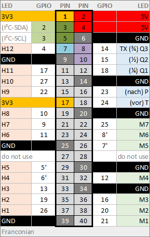
Using high luminance LEDs with a max. of 3.1 volts. Any color you like.
The current to the LEDs is limited by the RPi to 8 mA per GPIO via software. Possible values are 2, 4, 8, 16 (higher than 8 is not recommended). The usual resistor in line of the LED is not needed!
Powering
The RPi can be powered over a Micro-USB cable. Use a mobile phone power supply (for USB) or a nearby PC/server with USB.
The typical current at the 5 volts line is about 100 mA with peaks up to 300 mA when WiFi fires.
Design
Following the rules of the wording you are free to sculpt, form and place the illuminated words with any material and technique.
Upgrading
To use low voltage bulbs (5...24V), you can add 3 driver ICs like the ULN2803 directly to the RPi without a level shifter.
Pins for I²C are left free for additional IoT gadgets for e.g. temperature, humidity, luminosity, presence, notification...
Decisions
Why RPi?
Pros:
-
The RPi can use up to 26 GPIO pins directly without an additional port expander or shift register. Most smaller/cheaper controllers do not have enough pins to drive the 24 LEDs directly.
-
The RPi has a built in current limiter on the GPIO pins. Resistors in line to LEDs are not necessary.
-
The RPi Zero has on-board WiFi to get the correct time via NTP. No external RTC needed.
-
The RPi Zero has additional power and pins to run additional IoT features.
-
Faster development (and code change).
Cons:
-
Linux! Many steps to setup the controller. See chapter on GitHub Wiki...
-
Linux! Potential security leaks to your local network.
-
A little more expensive (about 20 Euro incl. MicroSD) than an ESP8266 (<7 Euro).
Why pigpio-lib?
Pros:
-
This lib can handle software PWM for ALL 26 GPIOs without any glitches.
-
Faster than BCM-lib.
-
Development and debugging can be done on your PC with remote control of the RPi GPIOs over the network.
-
Implementation for several programming languages available.
Cons:
-
pigpio-deamon permanently eats 7...10 percent of CPU time independent of how many GPIOs or PWMs are active.
-
The lib documentation has room for improvement.

 Nick Sayer
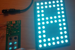
 makufelis-xyz
 Marius Taciuc
 Christoph Tack