Close
0%
0%

ESP8266 SDK Tutorial, Part 2

We dive deeper into the ESP SDK!

Public Chat
Similar projects worth following
Now that we have a grasp on the basics of the ESP Open SDK, we will start to use some of the peripheral features of the ESP8266.

Take a look at Part 1 of this tutorial series:

ESP8266 SDK TutorialLearn how to use the ESP8266 SDK. This is what the pros use!
ESP8266 Lua/NodeMCU TutorialA look at the NodeMCU Lua interpreter for the ESP8266.  Learn how to get to Blinky!
ESP8266 Arduino TutorialUse the Arduino IDE to simplify development and get up to speed very quickly!

And here's the links to the other tutorials in Part 2:

ESP8266 SDK Tutorial (You are here)Looking at using the linker to get PWM, and the included I2C libraries
ESP8266 Lua/NodeMCU TutorialUsing PWM and I2C with Lua!
ESP8266 Arduino Tutorial Using the Wire library for I2C, and AnalogWrite for fading!

Links to Part 3

ESP8266 SDK TutorialUsing MQTT to develop an IoT device
ESP8266 Lua/NodeMCU TutorialUsing the NodeMCU MQTT module to communicate with a cloud data service
ESP8266 Arduino TutorialWe use the simpler, more widely available HTTP protocol to log data to the cloud

Getting Help

If you run into trouble while following these tutorials, you have a few different options:

  • Ask in the discussion area below the article
  • Join the ##esp8266 channel on Freenode IRC and ping me (MrAureliusR) or ask anyone who is in there
  • Post on the ESP8266 Community Forums (note it can take a while to get a response!)
  • Send me a private message here on Hackaday

SDK Part 2: PWM and I2C

What is PWM?

Pulse-width modulation (PWM) is a method to control the average voltage of a signal without using analog means, such as a digital-to-analog converter (DAC) or digital potentiometer. By producing a square wave and changing the duty cycle, we control the amount of power delivered. The duty cycle is the ratio between the time the signal is in the high state and the low state. Think of it like an integral -- we are changing the area under the curve, which is equivalent to power. Take a look at this diagram:

Square wave at 50% duty cycle

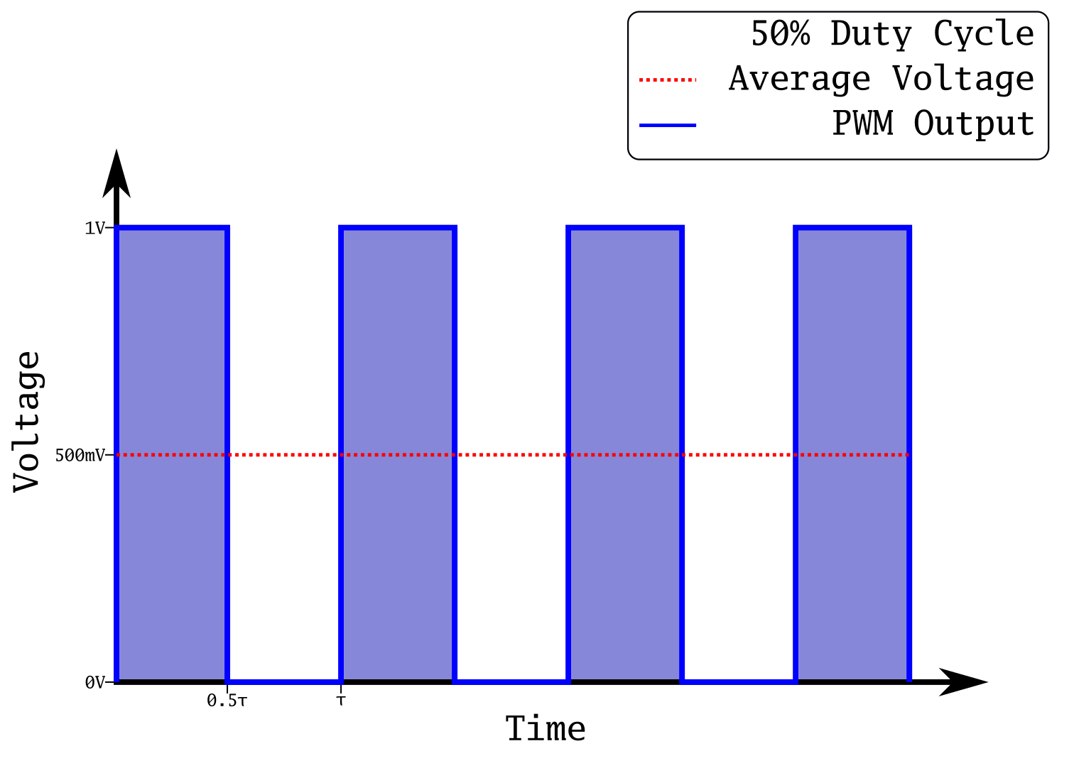
This is a plot of a square wave at 50% duty cycle. This means it spends half of its period (τ) in its high state, and the other half in its low state. In the case of this output, that means 1 V and 0 V respectively. The power transmitted is the integral of this plot, which is represented by the blue shading under the curve. Notice how that area is equal to the area during the low state; this is how we know it's at 50%. This has the effect of producing an average voltage of 500 mV. If we were to produce an analog output at 500 mV, and take the integral, it would be equal to the integral of this PWM output. This is extremely useful, as creating square waves is simple with a microcontroller, whereas creating analog voltages requires many extra components. 

What happens if we reduce that output to 30%?

Square wave with 30% duty cycle

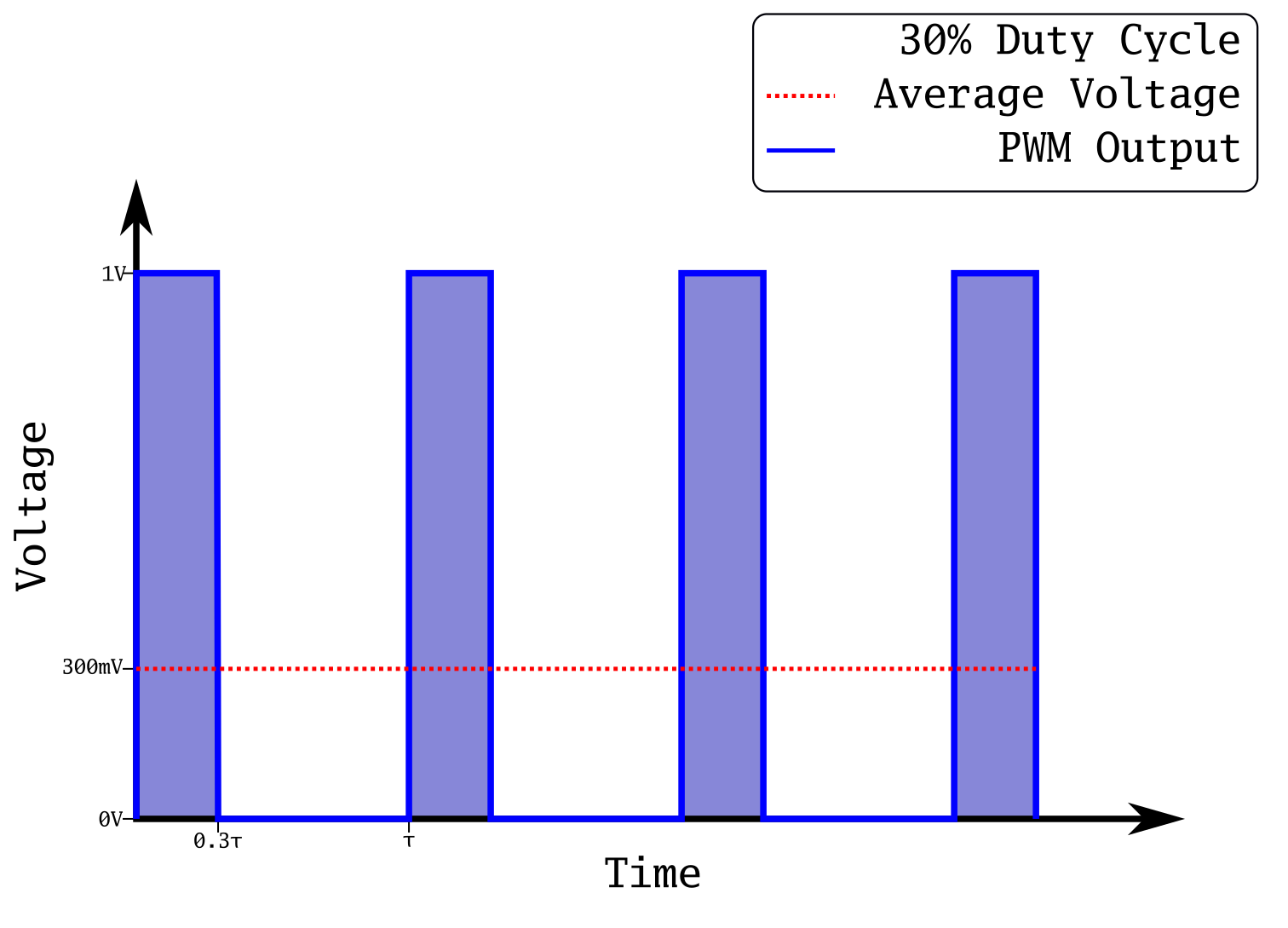
Now the on state is only on for 30% of the time. Our average voltage has now dropped to 300 mV. We have reduced the power sent out of our microcontroller pin just by changing the duty cycle of a square wave! If you are into math, you can prove that the analog voltage and the square wave are equivalent:

T is the period in seconds, and sgn() is the sign function. It's a simple way to get a perfect square wave on a plot. The integral of 0.5 from 0 to 20 is exactly 10, and the integral of the square wave will be almost exactly 10 as well. They will get closer with a faster period, and with more cycles. If you were to integrate to infinity, they would be exactly the same.

This is a common technique to control things like LED brightness, servo position, and buzzers. We are going to use it to fade an LED in the tutorial section below.

A quick side note about brightness of LEDs and PWM. The way human eyes respond to light is non-linear. Especially when LEDs are near the limit of their brightness, adding more current has a very small effect on the apparent brightness. So in order to scale the current going to...

Read more »

  • 1
    Using the PWM library with the SDK

    The SDK does come with a PWM library, which is great. This makes our task much easier. Using it is a bit convoluted, but it's nothing we can't tackle. We are going to use the same approach as in Part 1: create a function which will be called by an automatic timer periodically. In our function, we will change the duty cycle in order to get a nice smooth fade. Prior to this, we need to set up all the needed variables and get the PWM library initialised. 

    Let's start by declaring all our variables. We'll create variables for the PWM frequency, the duty cycle both in percent and as an absolute value, and also a variable to keep track of our state (increasing or decreasing). We also need to create the os_timer_t variable for our periodic timer. Because the max duty cycle absolute value changes with frequency, we create a variable for that as well. We'll calculate that value in the user_init function, per the SDK documentation.

    // ESP-12 modules have LED on GPIO2. Change to another GPIO
    // for other boards.
    static os_timer_t ledTimer;
    bool ascending = true;
    static const uint32_t frequency = 5000; // in hz, so 5kHz
    uint32_t maxDuty = 0;
    uint8_t ledDutyPercent = 10;
    uint8_t *pLedDutyPercent = &ledDutyPercent;
    uint32_t ledDuty = 0;
    uint32_t *pLedDuty = &ledDuty;

     Now we'll build our PWM control function. This will check to see if we've reached our maximum or minimum duty cycle, and switch the direction state if we have. It will also modify the duty cycle, and update the PWM output with the new duty cycle. All in all, it's fairly simple and self-explanatory:

    void ICACHE_FLASH_ATTR ledTimer_f(void *args) {
      if(*pLedDutyPercent == 100) {
        ascending = false;
      } else if (*pLedDutyPercent == 0) {
        ascending = true;
      }
      if(ascending == true) {
        (*pLedDutyPercent)++;
      } else if(ascending == false) {
        (*pLedDutyPercent)--;
      }
      *pLedDuty = (uint32_t)((*pLedDutyPercent/100.0) * (float)maxDuty);
      pwm_set_duty(*pLedDuty, 0);
      pwm_start();
    }

    We simply calculate the new duty cycle value, and update it with the pwm_set_duty() function. After each change we also have to call pwm_start() again, to force an update. Finally, let's look at the user_init function:

    void ICACHE_FLASH_ATTR user_init() {
      // init gpio subsytem
      gpio_init();
      maxDuty = (frequency * 1000)/45;
      uint32_t pwmInfo[1][3] = {{PERIPHS_IO_MUX_GPIO2_U,FUNC_GPIO2,2}};
      *pLedDuty = (uint32_t)((float)(ledDutyPercent/100.0) * (float)maxDuty);
      pwm_init(frequency, pLedDuty, 1, pwmInfo);
    
      // setup timer (20ms, repeating)
      os_timer_setfn(&ledTimer, (os_timer_func_t *)ledTimer_f, NULL);
      os_timer_arm(&ledTimer, 20, 1);
    }

    Remember that the first function to be called by the system must be called user_init(). We start by initializing the GPIO system with gpio_init(). Then we calculate the maximum duty cycle value. It follows a slightly odd formula, as given in the SDK documentation:

    The way we tell the PWM library which outputs we want to use is also slightly convoluted. We must create an n*3 dimensional array where n is the number of outputs we want. We're only using one, so we create a [1][3] array. The single row contains an array of three values: which GPIO register to use, the IO reuse of the corresponding pin and the GPIO number. We're using pin 2 as our output, so all our entries are related to GPIO channel 2. We then calculate the max duty cycle value using the above formula, and we pass all this information to the pwm_init() function. Note that the third parameter passed to pwm_init() is the number of PWM channels used, and not the PWM channel to be initialised. This is incorrectly documented and took me a while to figure out.

    Finally, we set up our timer for 20ms, pointing to our ledTimer_f() function. This is set as an automatic timer, so after it's armed that's all we need to do! Phew.

  • 2
    PWM Code

    Now that we have all the pieces, let's put them all together:

    #include <math.h>
    #include "ets_sys.h"
    #include "osapi.h"
    #include "gpio.h"
    #include "pwm.h"
    #include "os_type.h"
    
    // ESP-12 modules have LED on GPIO2. Change to another GPIO
    // for other boards.
    static const int pin = 2;
    static os_timer_t ledTimer;
    bool ascending = true;
    static const uint32_t frequency = 5000; // in hz, so 5kHz
    uint32_t maxDuty = 0;
    uint8_t ledDutyPercent = 10;
    uint8_t *pLedDutyPercent = &ledDutyPercent;
    uint32_t ledDuty = 0;
    uint32_t *pLedDuty = &ledDuty;
    
    void ICACHE_FLASH_ATTR ledTimer_f(void *args) {
      if(*pLedDutyPercent == 100) {
        ascending = false;
      } else if (*pLedDutyPercent == 0) {
        ascending = true;
      }
      if(ascending == true) {
        (*pLedDutyPercent)++;
      } else if(ascending == false) {
        (*pLedDutyPercent)--;
      }
      *pLedDuty = (uint32_t)((*pLedDutyPercent/100.0) * (float)maxDuty);
      pwm_set_duty(*pLedDuty, 0);
      pwm_start();
    }
    
    void ICACHE_FLASH_ATTR user_init() {
      // init gpio subsytem
      gpio_init();
      maxDuty = (frequency * 1000)/45;
      uint32_t pwmInfo[1][3] = {{PERIPHS_IO_MUX_GPIO2_U,FUNC_GPIO2,2}};
      *pLedDuty = (uint32_t)((float)(ledDutyPercent/100.0) * (float)maxDuty);
      pwm_init(frequency, pLedDuty, 1, pwmInfo);
    
      // setup timer (20ms, repeating)
      os_timer_setfn(&ledTimer, (os_timer_func_t *)ledTimer_f, NULL);
      os_timer_arm(&ledTimer, 20, 1);
    }

    We can use the Makefile we created in Part 1, but we have to make one small change. If we were to try and compile the code right now, the linker wouldn't know where to find the functions pwm_set_duty() and pwm_start(). So, let's open our Makefile and make one small change:

    LDLIBS=-nostdlib -Wl,-Map=output.map -Wl,--start-group -lc -lm -lhal -lpp -llwip -lphy -lnet80211 -lwpa -lmain -lpwm -Wl,--end-group -lgcc

    Notice the addition of -lpwm, the PWM library. Now the linker has all the pieces it needs to compile the code. Just like in part 1, you can compile and flash the code by using the command:

    $ make flash

    Remember to make sure you have the correct port set in your Makefile. Everything should compile and program smoothly. If it doesn't take a careful look at the errors you get. As always, if you get stuck, refer to the "Getting Help" section in the project description! 

  • 3
    Using the I2C library with the SDK

    The ESP8266 does not have a hardware I2C module, thus all I2C comms must be done in software. The ESP8266 SDK does include an I2C software implementation, which is handy, and we'll be taking advantage of it. We will be modifying our Makefile again, as well as copying the I2C library file from the ESP8266 NONOS SDK folder.

    Start by grabbing i2c_master.c from your ESP SDK folder:

    $ cp ~/workspace/ESP8266/esp-open-sdk/ESP8266_NONOS_SDK-2.1.0-18-g61248df/driver_lib/driver/i2c_master.c ~/workspace/ESP8266/C/i2ctime/i2c_master.c

    This is how I have my workspace organised, as I've mention previously. However, your layout may vary, and the name of your ESP8266_NONOS_SDK folder will likely be different. We will also need the header file i2c_master.h, though it needs to go in a subfolder called "driver":

    $ mkdir ~/workspace/ESP8266/C/i2ctime/driver/
    $ cp ~/workspace/ESP8266/esp-open-sdk/ESP8266_NONOS_SDK-2.1.0-18-g61248df/driver_lib/include/driver/i2c_master.h ~/workspace/ESP8266/C/i2ctime/driver/

    We also need to update our Makefile so that the i2c_master library gets built and linked into our executable. To do this, we simply add a few new lines to our Makefile:

    P=main
    CC=xtensa-lx106-elf-gcc
    LDLIBS=-nostdlib -ggdb -Wl,-Map=output.map -Wl,--start-group -lm -lc -lhal -lpp -llwip -lphy -lnet80211 -lwpa -lat -lwpa2 -lmain -Wl,--end-group -lgcc
    CFLAGS=-I. -mlongcalls -std=gnu11
    LDFLAGS=-Teagle.app.v6.ld
    
    all: $(P)
    
    $(P)-0x00000.bin: $(P)
        esptool.py elf2image $^
    
    $(P): $(P).o i2c_master.o
    
    i2c_master.o: i2c_master.c
    
    $(P).o: $(P).c
    
    flash: $(P)-0x00000.bin
        esptool.py --port /dev/feather0 write_flash 0 $(P)-0x00000.bin 0x10000 $(P)-0x10000.bin
    
    clean:
        rm -f $(P) *.o $(P)-0x00000.bin $(P)-0x10000.bin

     We tell it that $(P) is made not only from our main.o file, but also from i2c_master.o. The next line gives instructions on how to make i2c_master.o: by compiling i2c_master.c, of course! I also added -std=gnu11 to the CFLAGS as I like to use some of the features of newer versions of C.

    Note that the pin definitions for SCL and SDA are inside i2c_master.h, near the top. These pins are labelled on the back of the Feather:

    Alright, let's dive into the code itself.

View all 4 instructions

Enjoy this project?

Share

Discussions

Similar Projects

Does this project spark your interest?

Become a member to follow this project and never miss any updates