 Alastair Young
I'll break out specific component details into build instructions and use project logs as a calendar of progress.
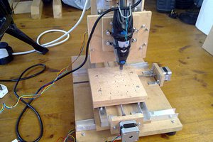
The base system is the EleksMaker® EleksLaser-A3 Pro 2500mW Laser Engraving Machine which was on sale at banggood.com for $190. There is a version without the laser for $40 less, and the laser itself is $120. Seeing this bargain price triggered me to finally actually do this. Getting it with the laser means that if I don't get the PNP working (or useful) I still have a laser engraver to play with.
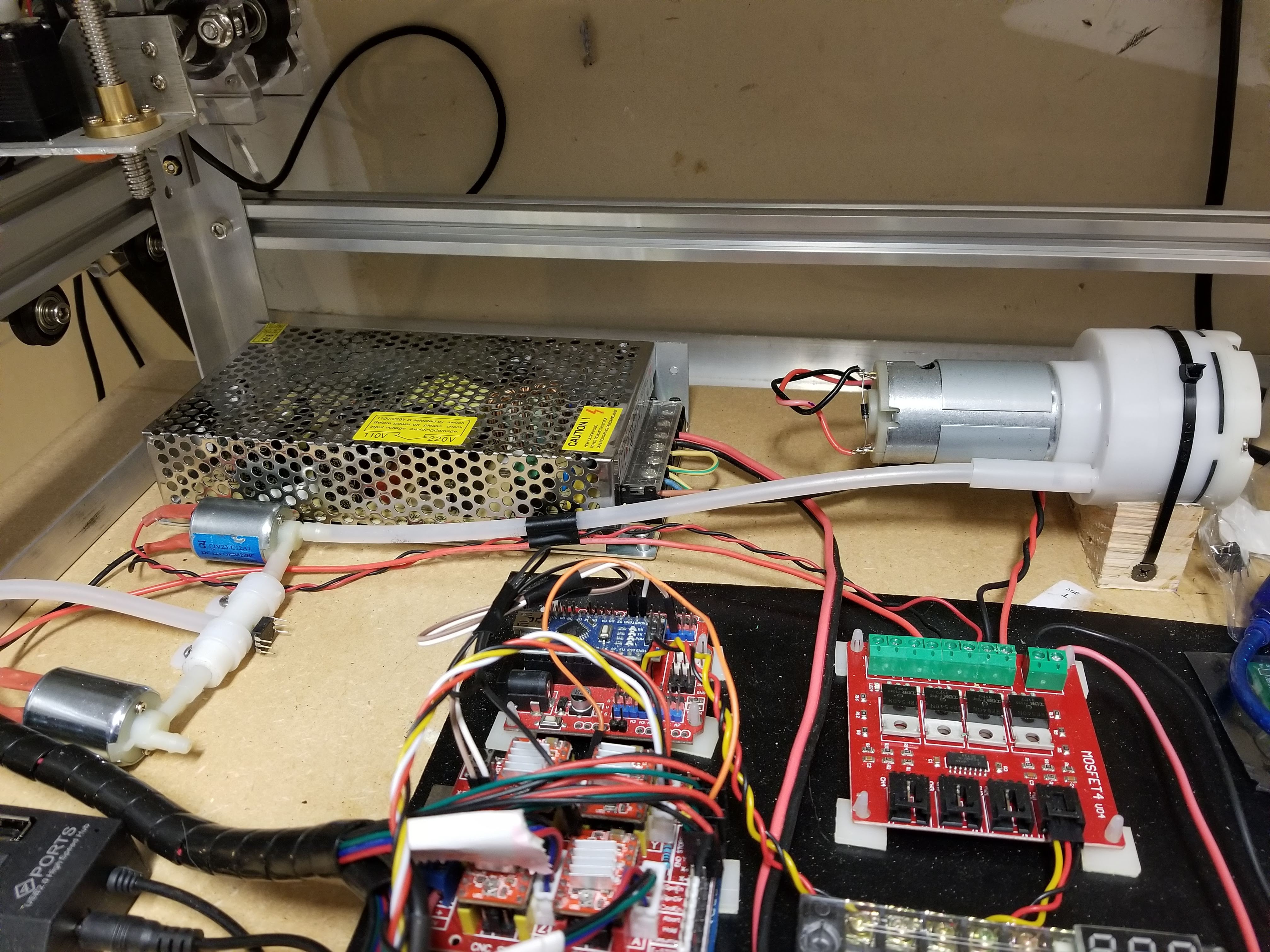
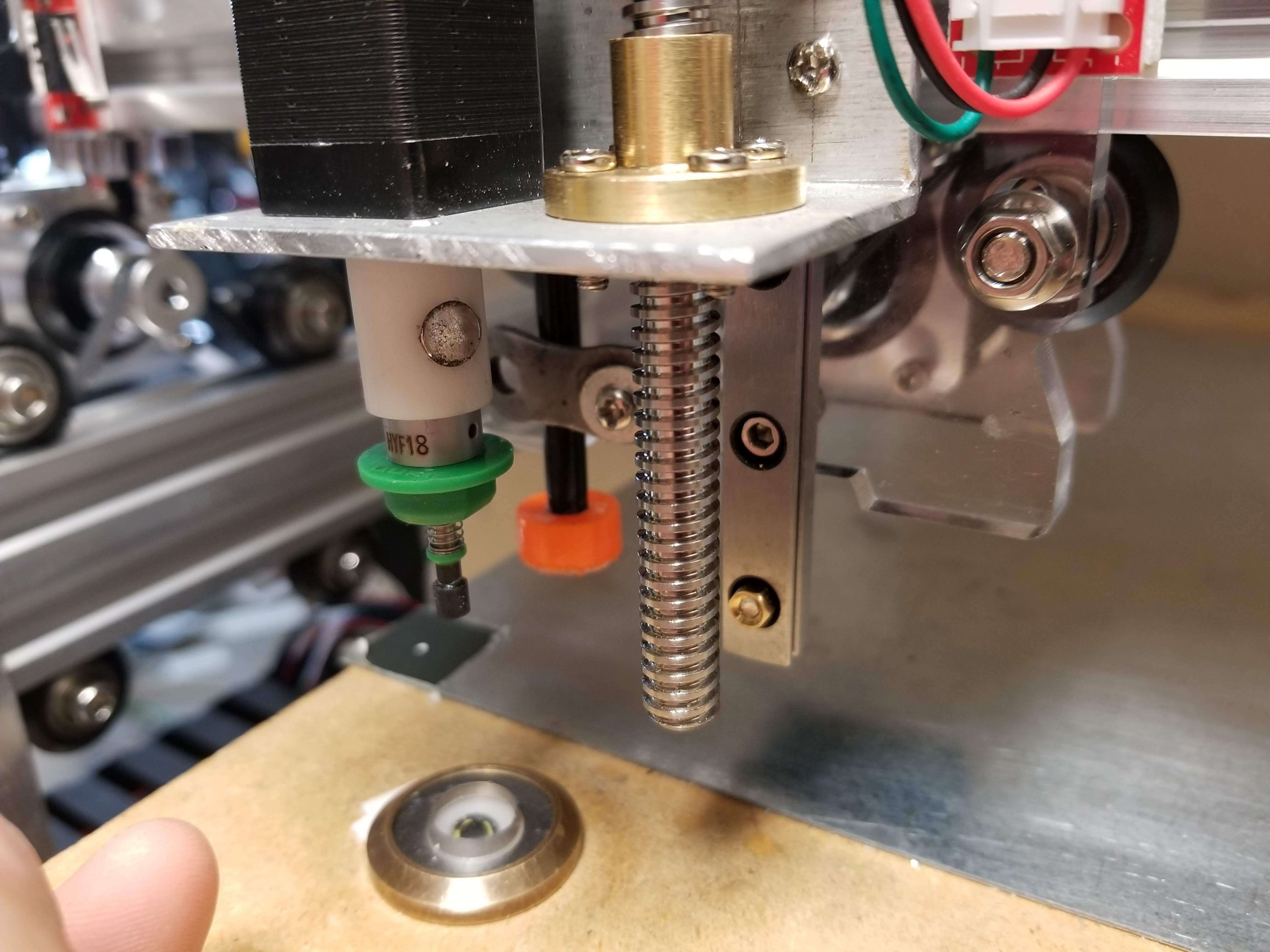
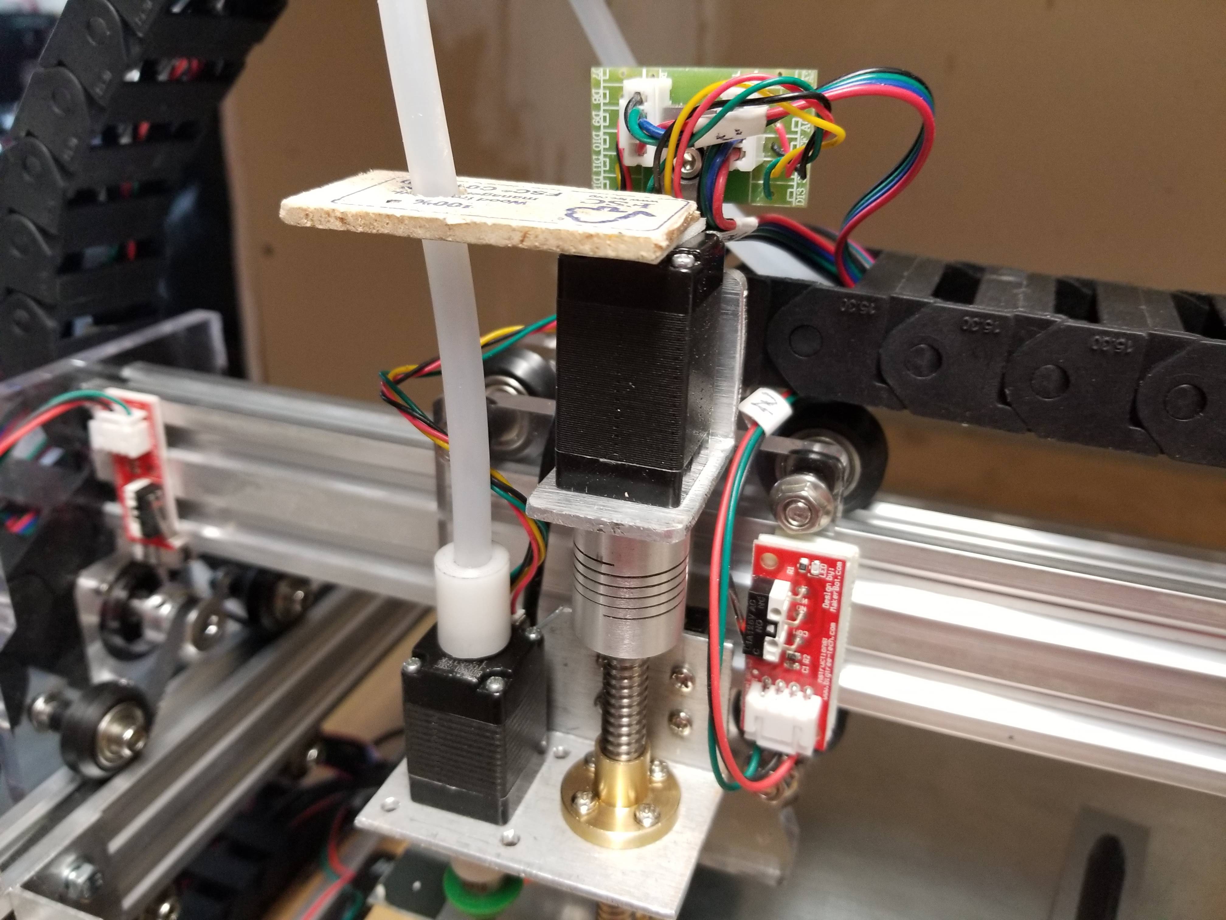
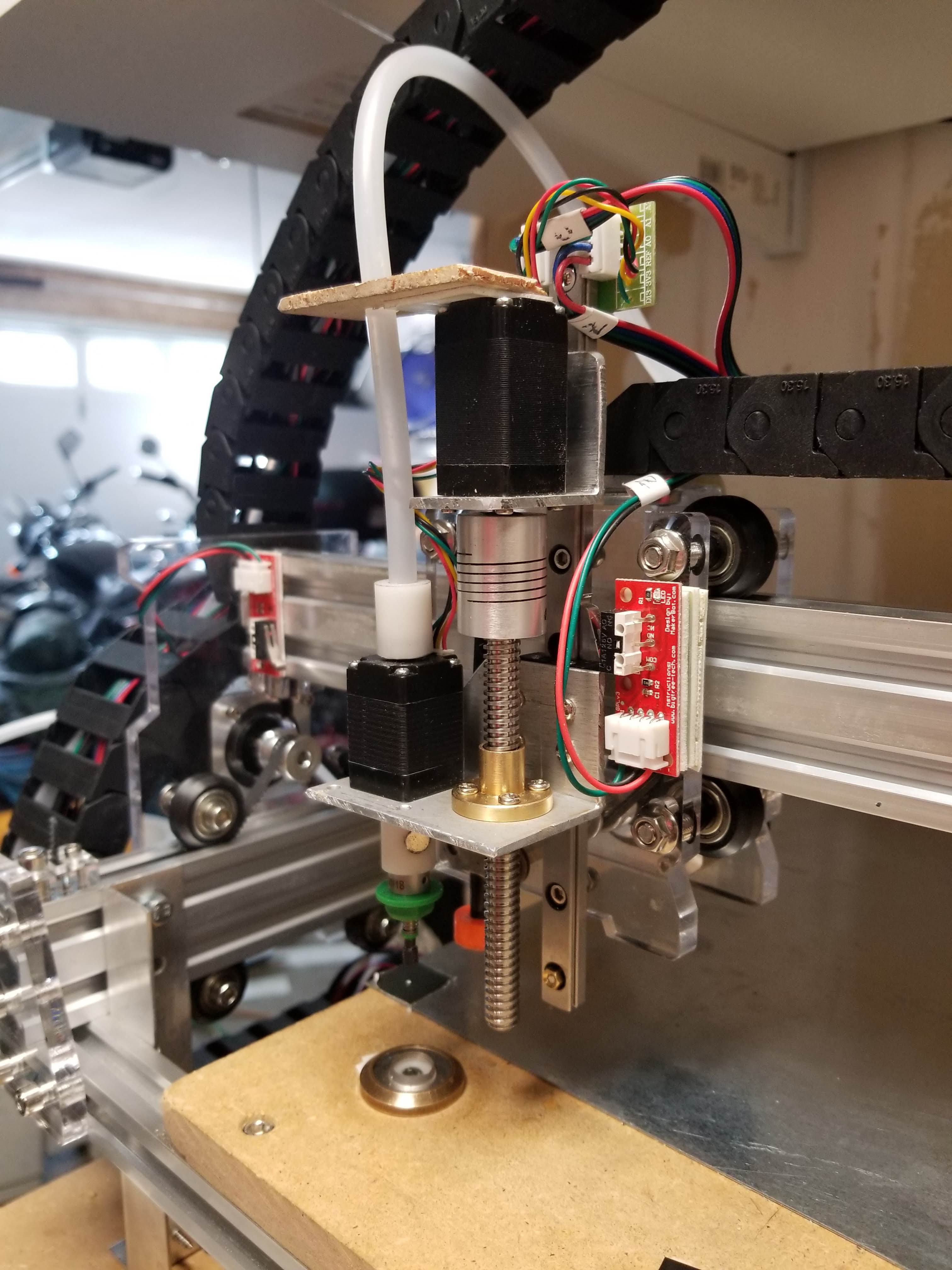
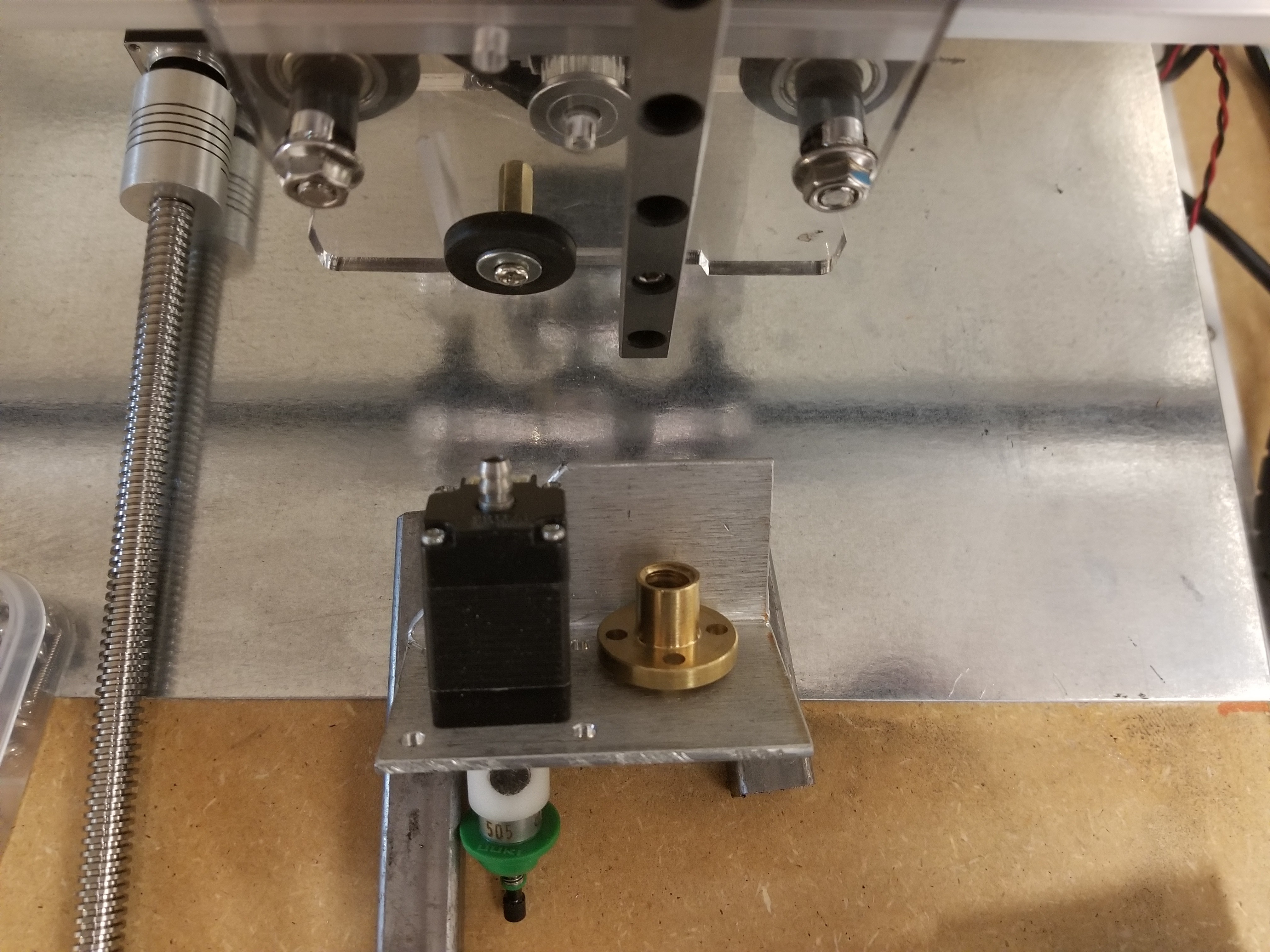
Current status is 4 axis functional with a vacuum hose attached, and visual homing worked out - also up and down cameras done.
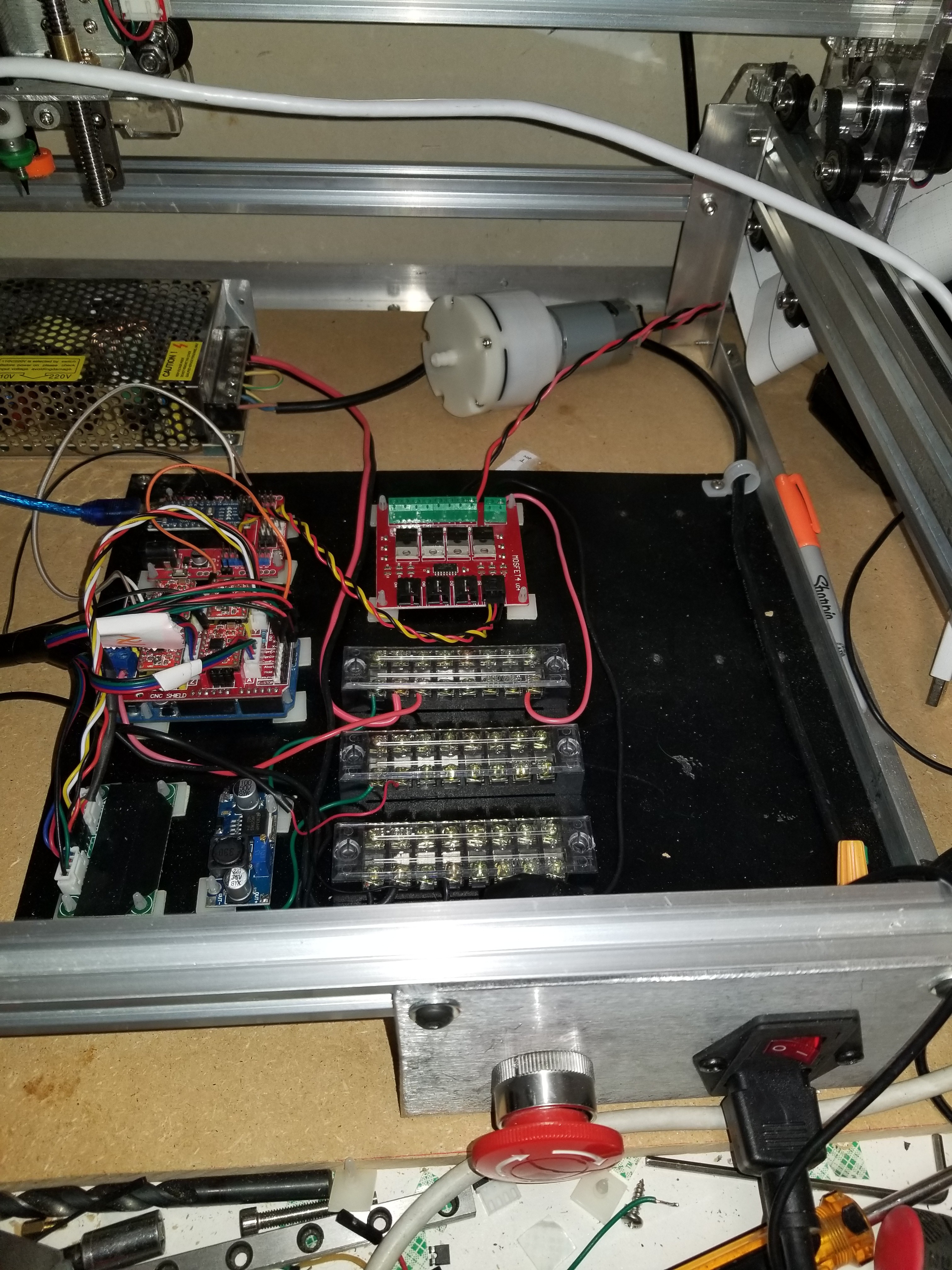
Currently working on back end wiring stuff - wall-wart elimination - fuses - emergency stop.

 dar.ryl
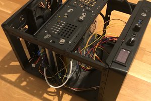
 vincentmakes
 smashedagainst
One of the random, one-off hacks here... and I agree with you. :) Choosing a motion platform that is stable is pretty important. Beyond that, I have a project you may be interested in...