 SortOfEngineer
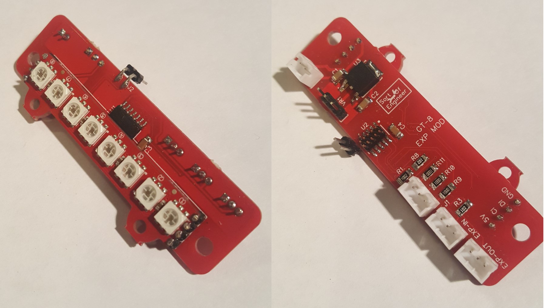
I was kinda lucky in having already conceived and done some prep work for this project at the time the blink an LED contest was announced, and I was able to get a board spun in time (without expediting).
(EDIT: moved one of the videos to the front of the write-up, a second video is at the end)
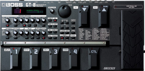
The motivation for doing this project is that I use my Boss GT-8 guitar effects pedal quite a bit in live performance, and I rely on the using the expression pedal for volume. The GT-8 is not as nice as having discrete pedals for various effects, but it does get the job done, is convenient, and offers a lot of value in situations where I don't even get an amp and have to go directly to the house mixer.
Usually, I will set my volume during sound check with the expression pedal set to where I think ~70% is. This allows a little extra room to get louder (I use the volume knob on the guitar mostly during playing) if the sound changes when the room gets filled up or the sound guy gets a little too aggressive with cuts. After sound check, I'll turn the volume pedal all the way down since I have no control over house volume. I can also do during any down time on stage when someone is talking, or set breaks, or when switching guitars, etc. where I don't want any accidental sound or pops to get through. By being able to see where the volume is actually set, I can set it back to the original position. I can also make relative changes more easily.
The expression pedal is nothing more than a potentiometer. My initial thought was simply insert my board between the pot and the main board. There is a 3 conductor cable that would have almost everything I need: power, ground, and a sense for the pot. For the LED meter itself, I had chose to use an pre-made APA-102 module with 8 LED's. I had used WS2812 before... not a fan. But the APA-102's do require 5V, so that had to be grabbed elsewhere. I've marked up the internals of the GT-8 to show where different signals are.
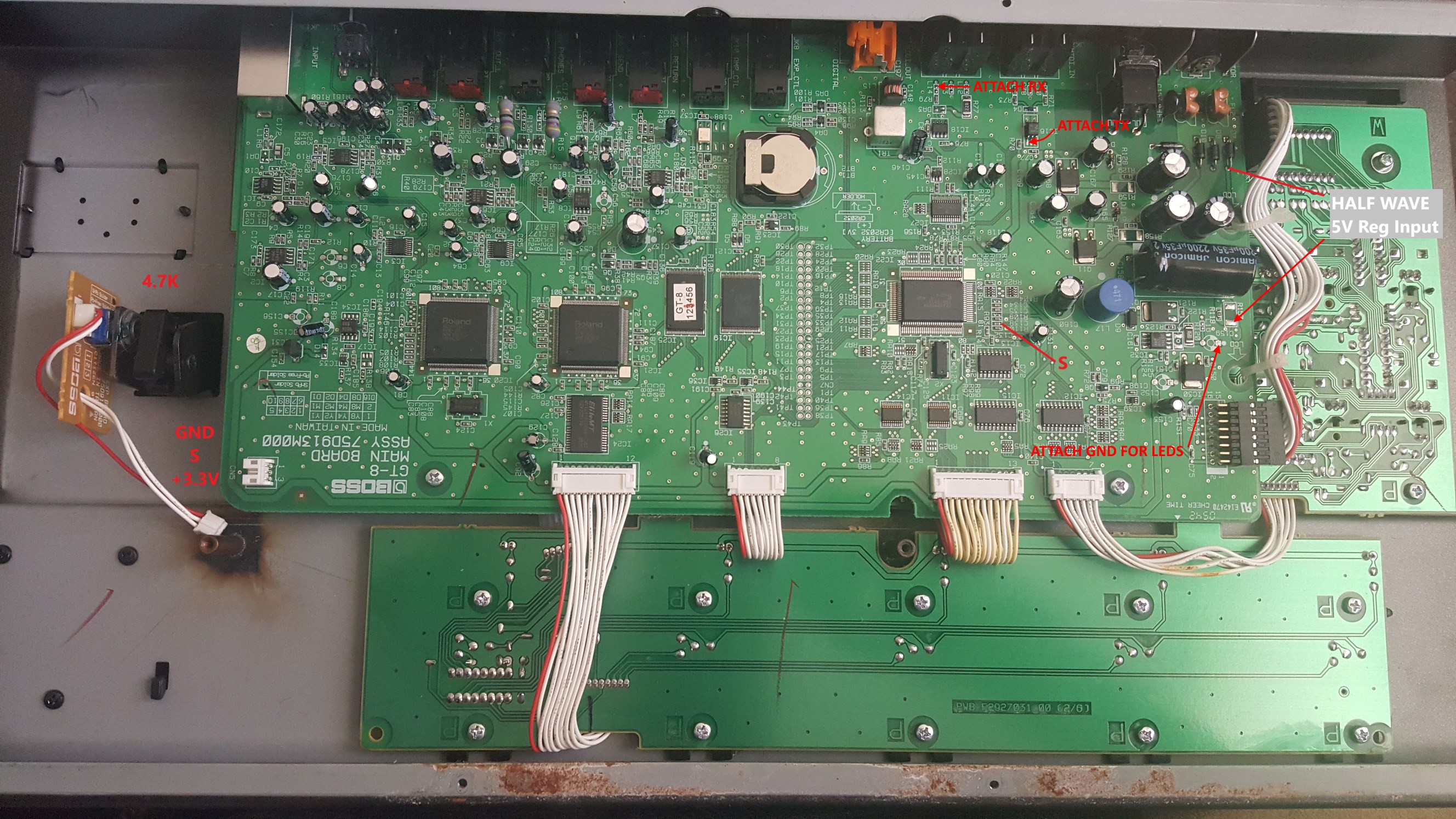
As it turns out though, the GT-8 outputs MIDI data for the expression pedal in real time. I didn't realize it until after I had sent the PCB out to be made. During my initial testing, I had unplugged the pedal to look at voltages, and ended up looking into the MIDI at the same time to see what the GT-8 sent out.... without plugging the pedal pot back in... On the bright side though, I always like to put a UART somewhere for debug. I was able to solder a connector awkwardly on the board and use the UART for my MIDI communication. This actually turned out to be a nicer solution, as the MIDI data doesn't need to be converted from analog reading like the pot (learning the pot min, max, then having to scale).
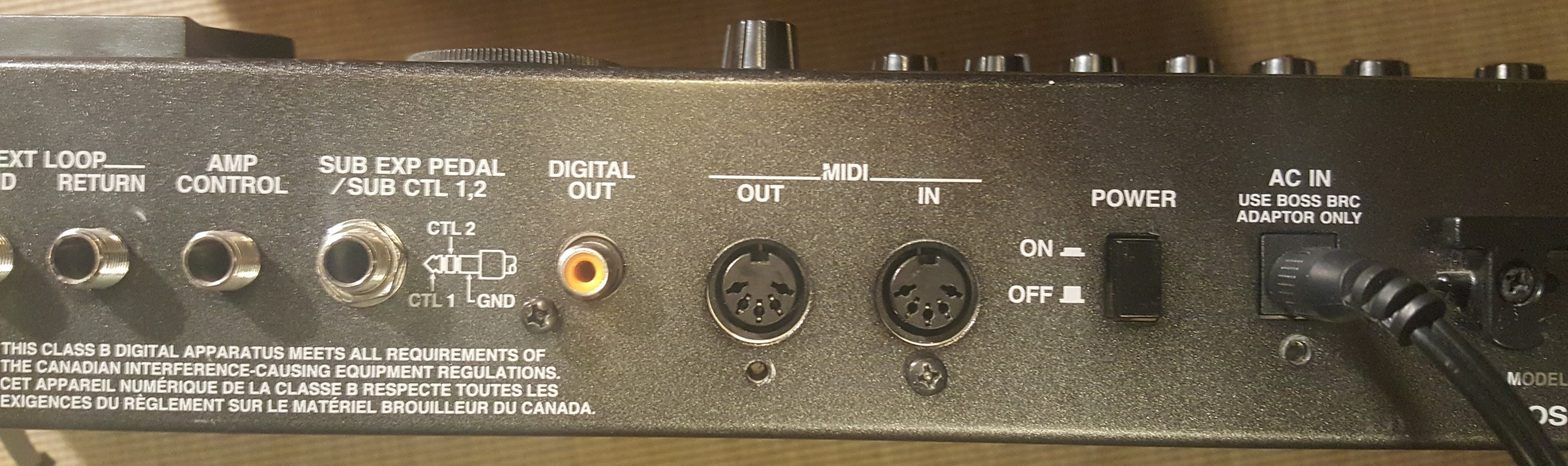
I am able to connect the UART in such a way as to not interfere with the normal MIDI communication to external devices, but still send and receive. I don't want to get into much MIDI specifics, but it's a pretty useful protocol when doing music stuff.
Oh, by the way, this project centers around an Atmel SAMD09C13 microcontroller. I haven't used an arm processor in a finished project before, so this was a great opportunity to do so. Had to do everything bare metal as the Atmel ASF generates code way too big to fit on the chip. There is also a quirk using the -nano flag for the standard libraries the requires an esoteric fix (maybe document it later?).
So the LED meter works as such: when the GT-8 is turned on, the meter waits 5 seconds for the unit to boot up, then sends a SysEx MIDI message to query the current volume, since the pedal position is only sent when the pedal moves, so an initial value is not known. As the pedal is moved my board just sniffs the MIDI and gets the current position. When the pedal is pushed all the way forward, there is effectively a 'button' at the end of travel that requires a bit of oomph to engage. For most patches this switches between the pedal controlling...
Read more »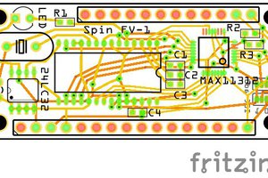
 bobgreenwade
 Alan Green
 Adam Demuri
 Pierre-Loup M.