 matthewkleinmann
The first step was pondering various designs. Being an electronics junkee my first though was a couple big 7 segment displays. with LED's. I have a near limitless supply of 1/4" OSB and my head was already a buzz making all the little cell dividers and strips of LED's and dropping resistors that looked like HO train track to fill the segments in. Perhaps I will try this someday, but I bailed on this for a few reasons. The two big reasons is it would have to be super bright to be easily readable on a bright winter day with the sun out and snow on the ground. The second is that would require power and we don't want cords or cables running around. Trip hazards. Going rechargeable puts the onus of having someone responsible for charging it before each use. Batteries would be an ongoing expense.. Sadly, I started to think the electrics might not be the best way to go.
The next thought was to make segments on my 3D printer that could be manually rotated or flipped like a flip dot or flip segment display, but manually flipped This would limit the size of the digits to about 8" wide , the width of my 3D printers bed, Not bad really. At first I had thought about making 3D printed "corners" for the segments to rotate in. Than I thought of an all 3D printed plastic frame. I soon decided that he segments could fit in a wooden frame as my CAD skills are not up to designing a multi part snap together 3D printed plastic frame. I really liked this idea. The fly in the ointment with this one was the large amount of 3D printing. I should be able to crank out at least 4 of the segments at a time as they would fit on my printers bed, but I never do that well. I can do one at a time all day and night (and that is what one segment would pretty much take to print..) but if I queue up more without fail one will start to peel up until the head hits it and pulls it off and it crashes into the next one knocking that off, right on down the line. In the unlikely event one or two survive, the steppers have both missed steps and the printing of the remaining pieces is offset. So I bailed on this idea because of the amount of printing time and it being the summer (lots of more fun things to be doing than babysitting the 3D printer).
Moving along, the next thought was to use PVC pipe for the segments and rotate it instead of flip it, At first I thought about making 3D printed ball ends for the PVC that would fit into 3D printed sockets. Again on a wooden frame. After thinking about it, the 3D printing seemed to be expensive and slow, plus my limited CAD skills would frustrate me. I can CAD things but it takes longer to draw up the part in CAD than is takes me to make it out of wood.
The next idea was PVC pipe and off the shelf PVC fittings. I had a few big pieces of 1/2" PVC pipe and all of the fittings were under a half buck a pop at the local hardware store, and even less at one of the big box stores in town. The only fly in the ointment with these was the fittings for the center horizontal segment. You can buy PVC furniture fittings that are T's with one vertical sprew coming out of them, but they are expensive. I opted to just use Tee's to hold the center segments and if necessary I could glue shims under them.
My segments are about 9" end to end made out of 1/2" PVC that I had kicking around. I cut them out on my chop saw with a stop so I could crank them out quickly and consistently.
I sanded the pvc pieces down prior to painting them. You can just use sand paper. I built a jig on my wood lathe to make it easier. It is an oak rod. One end fits in my drill and the other end slowly tapers from skinny to thick and you can stick the PVC on it and spin it with the drill. Makes sanding easy. I put my drill in my vice and used a tie wrap to hold the trigger at a good speed. I seem to have lost that piece, but it is not hard to envision or duplicate.
Once the pieces were sanded, it was time to paint them. How to get them half black and half day glow pink? I am blessed to have smart friends. My friend Kirk came up with the solution to painting the segments. I laid them all out next to each other and used some scrap wood and my air stapler to make a frame that held them tightly together. I stood the frame up and spray painted one side of all of the segments flat black and the other side of all of them day glow pink. This color glows under a black light as well as being very visible in daylight. If I ever need this to be visible in the dark I could hook up some UV LED's to shine on it.. Paint all the Tees and Ells while you are doing the black.
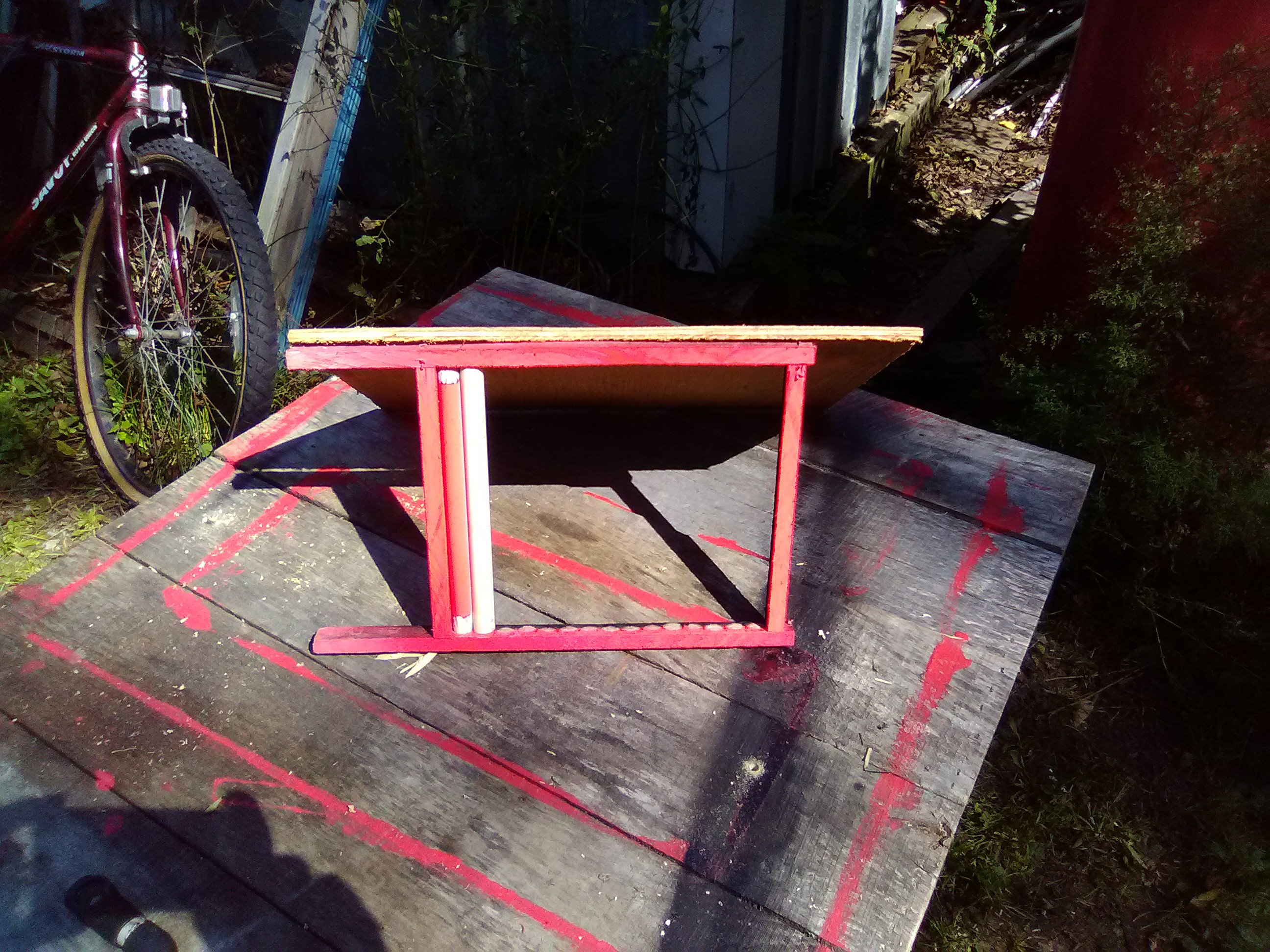
This is a mockup of the pink side being painted. Obviously I did all 15 segments at once. This is the frame I used to paint my 15 segments. I made one more segment than I needed "just in case" . I actually painted the black side first. I figured if the day glow drips into the pink I could mask it with a black sharpie. Also, I painted the segments standing up just like this, figuring any drips would wind up on the ends and get sanded off in the next step anyway.
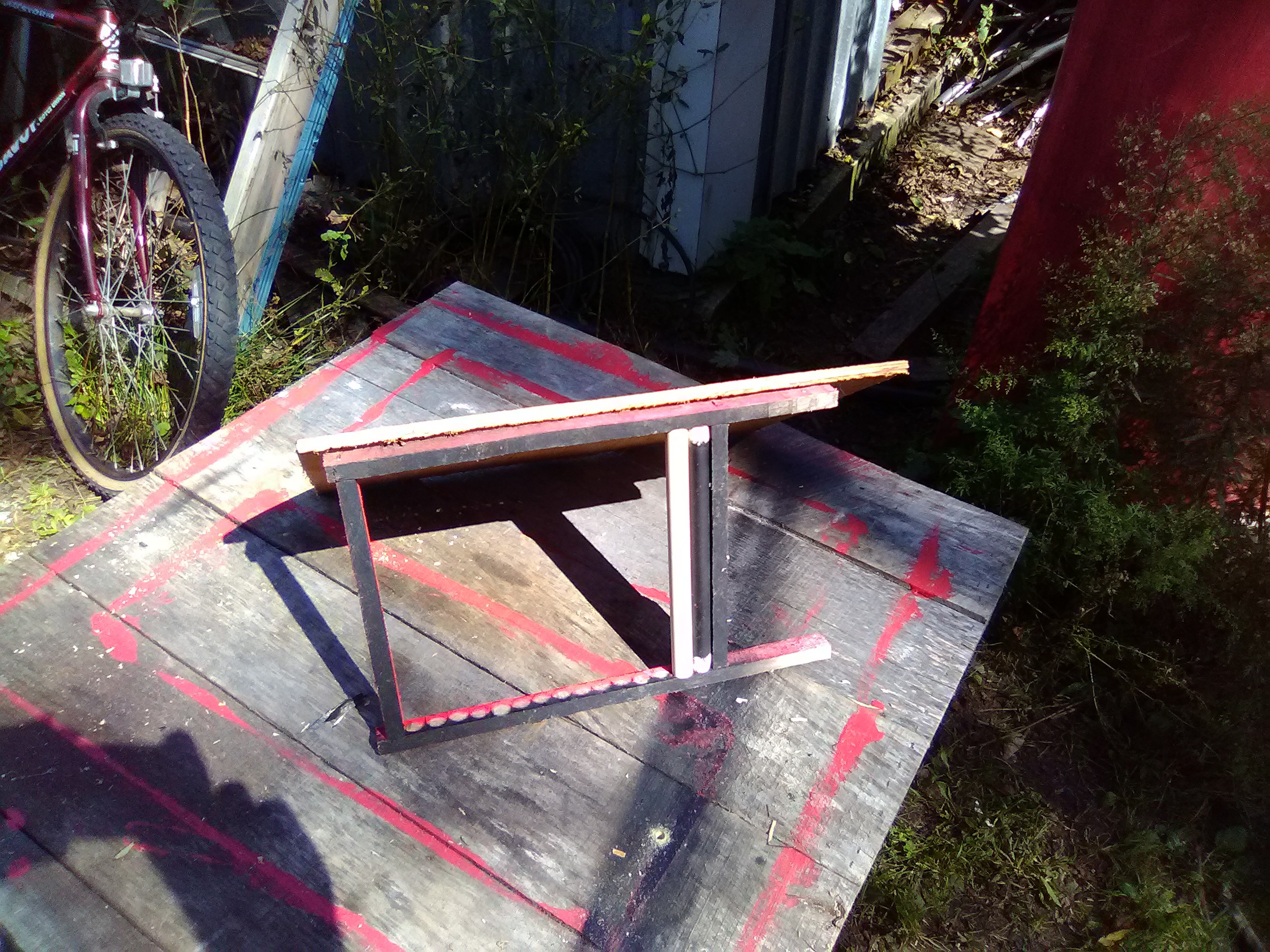 This is mock up of the black side being painted, Again in real life the frame has 15 segments in it, and they fit tightly together so the paint can only hit one half of the PVC. When the black side was done, the frame was carefully turned around, and the pink side was painted.
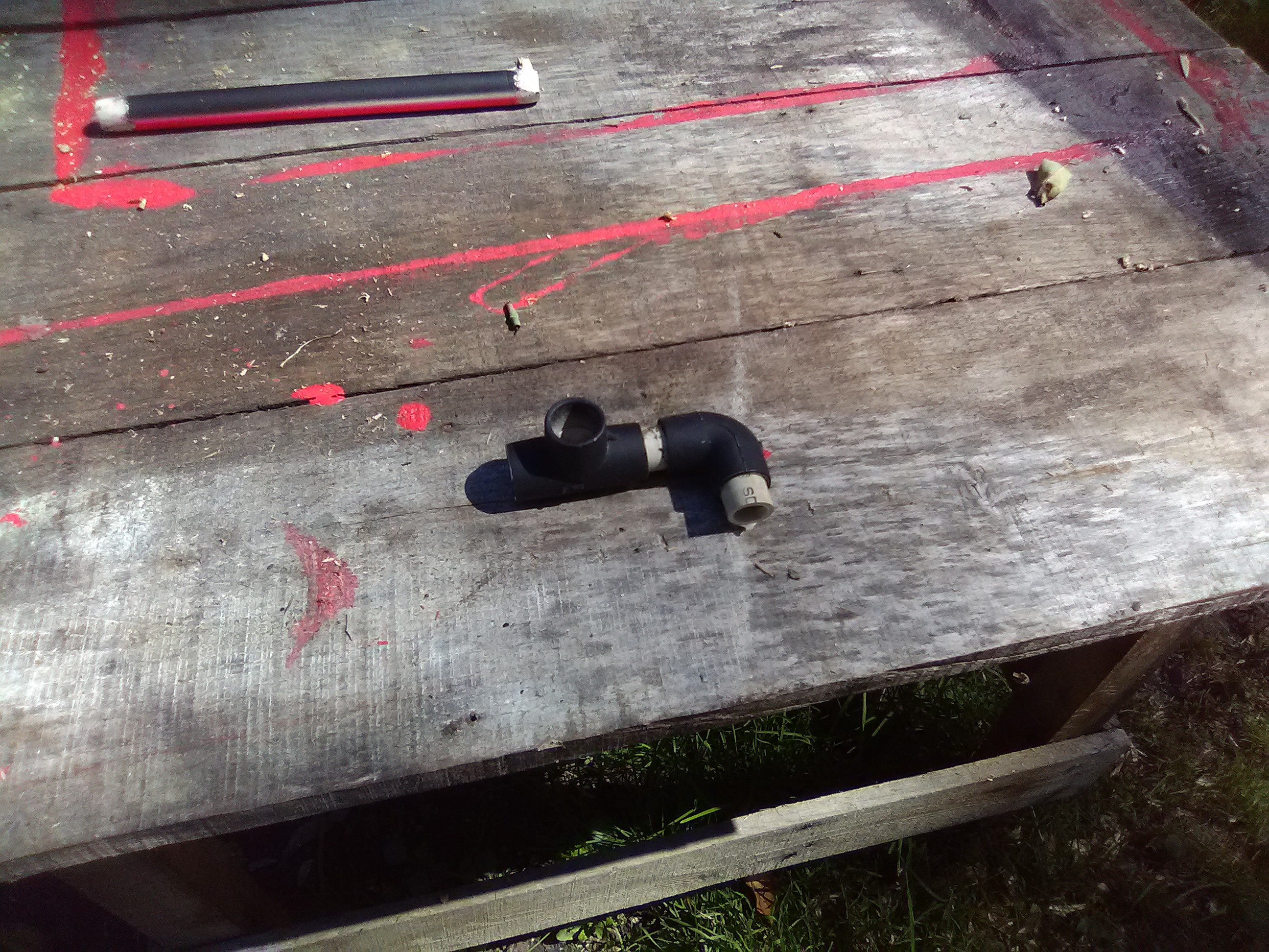
This is a detail of a painted segment. You can see the day glow pink and black meet pretty nicely down the length of the segment. The white stripe could be fixed with a black sharpie, but as it turns out , it is not at all necessary. There is also the exploded construction details of thow the Tee and the Ell fit together. The fitting on the left is a Tee. The small piece that joins them is short enough to be totally hidden when the pieces are pushed together. The short piece coming off of the Ell is short enough that when pushed all the way into the Ell, it protrudes a bit less than one half of an inch, and fits tightly in a hole in the back board.
A half inch at the end of each segment was sanded down so they can spin freely in the PVC fittings. I built a gizmo to do this with my wood lathe, but it would be just as easy to spin the ends of the PVC on a belt sander. My gizmo was a piece of oak that I spin one end down on so I could chuck up in my power drill and the other end had a hole a bit bigger than the PVC that I was able to glue a little piece of sandpaper in. Spin the jig up and stick the end of the pipe in and you are good to go.
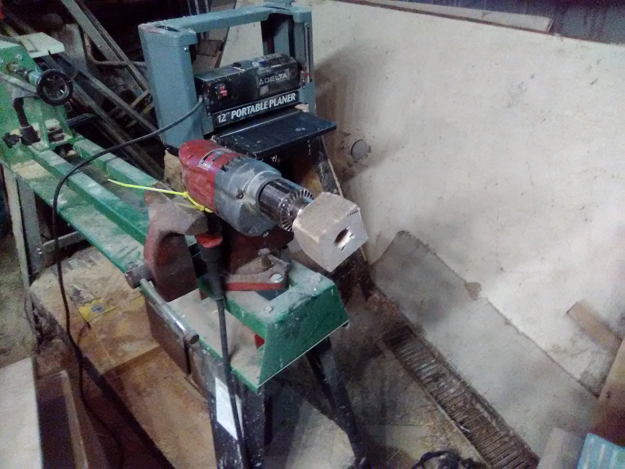
This is the jig I made for sanding down the ends of the segments. I fit sandpaper in the hole and spin the thing with my electric drill as shown. And yes, the vice is mounted to my lathe. It mounts with two bars that cross the lathe's rails. It can be moved or removed quickly and has been really handy in the shop.
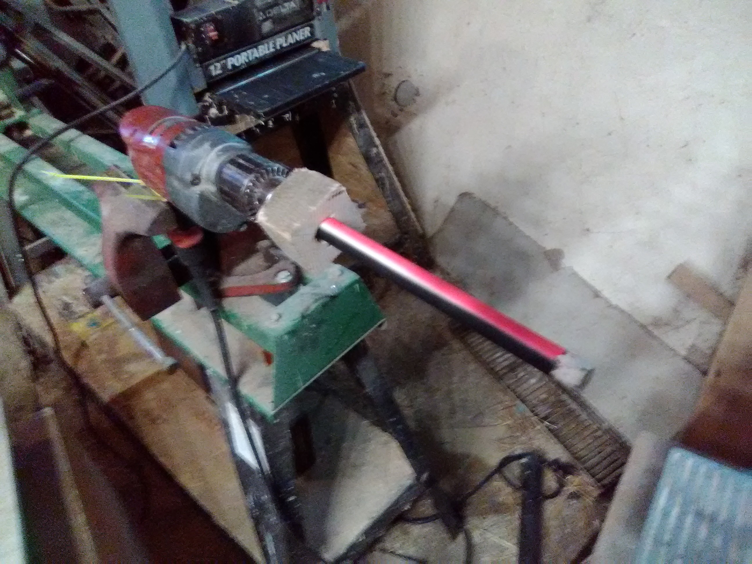
This is what it looked like taking some off the end of one of the segments. with the jig. I tend to build jigs and fixtures like I am going to build a lot of things. Truthfully, if it was less than 15 segments I would have just used a sander or a file. HOwever, now if I wanna make another sign I am all tooled up to do it.
I gave the backboard a skim coat of wood filler and sanded it and painted it black. Sadly I grabbed gloss and not flat, but it still looks good. A warning there. If you buy the 97 cent black spray paint at WalMart, it is nice spray paint, but the caps on the gloss and flat black look a lot alike. Don't trust the cap! Read the label!
I framed around the back of the backboard with furring strips to keep it from curling. I painted the back the same as the front, but the back could be painted with chalkboard paint so that side could be used for custom signage.
I drilled holes half way through the back board with a forstner bit. The holes were just big enough to hold the PVC pipe stubs. It was a tight fit. I mixed up 2 part epoxy right in all of the 8 holes and stirred it up good and plunked the digits into them. Hint: Assemble the digits first and hold them together when you place them in the holes.
 This is not the actual backboard. This was a mock up that I created to test to make sure my measurements were correct and that everything fit well. It would have bummed me out if I had screwed up and I had cut into the real backboard after finishing it and sanding it and painting it. If I want to make another sign I can just put this piece of OSB over the plywood, clamp them together place, and place my forstner bit in the holes. No need to even measure.
I did not glue the Ell's and Tee's together. I spent a lot of time debating that. I was concerned that I did not have a good jog to keep them at the proper angles to each other. As it turned out, once mounted everything fit really nice and there is just enough play in the thing to pop a segment out if you have to replace it or what not. The segments will not come out easily. Also I pondered putting shims in under the Tee's for the center segments on each side, but once the digits were glued into the frame, they hang real nice without any shimming.
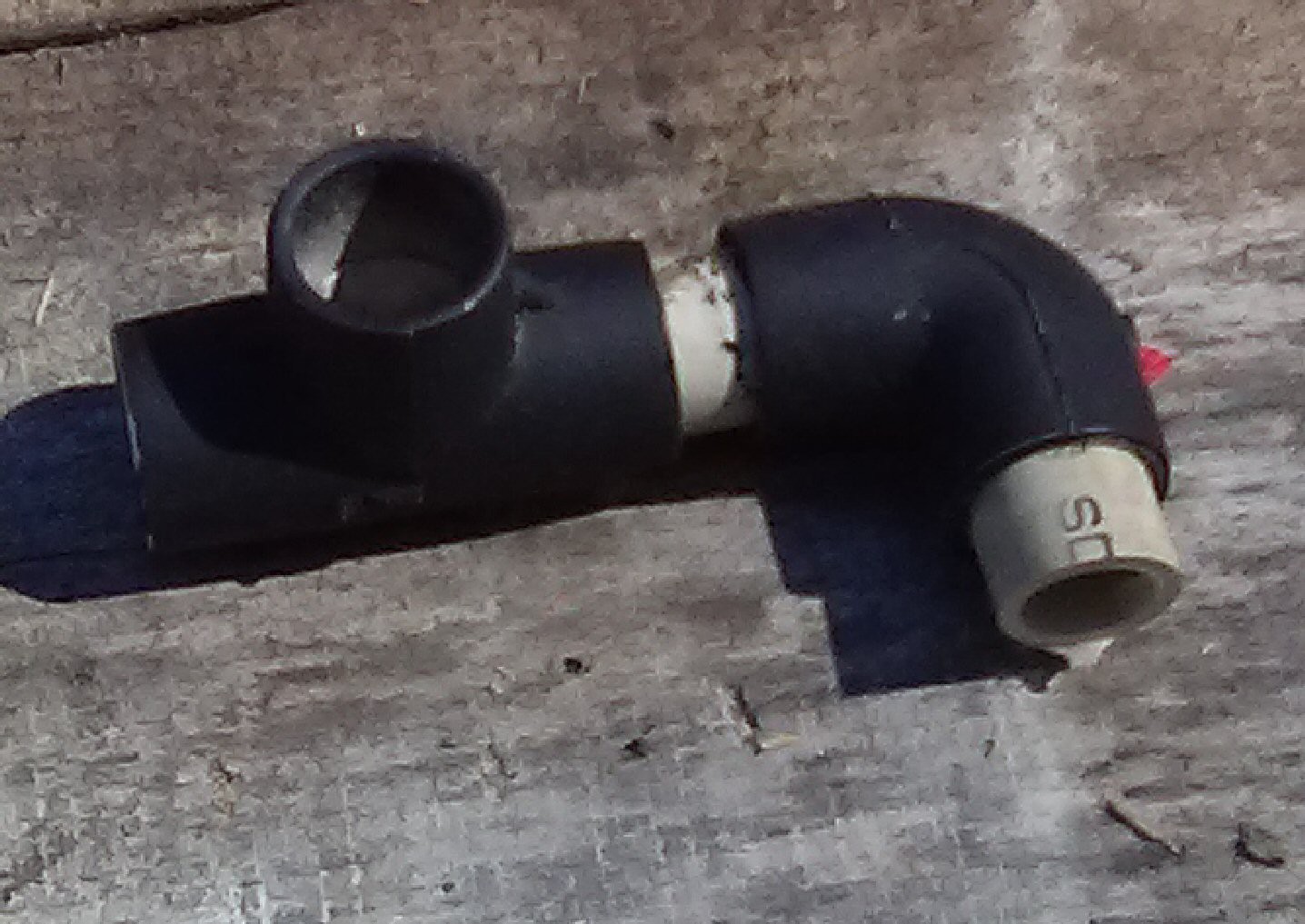 Close up of the Tee and Ell assembly. The stub coming out of the Ell goes into the hole in the back board. Segents go into the other two holes. I tested and pondered how to mount the Tee's and Ell's as the support could also come from the bottom. In the end, I liked the way things looked with the support off to the side better. Even though the support does not change the aspect ratio of the digit, it does change the aspect ratio of the mounting holes and having more even aspected mounting system agreed with my sensibilities more. YMMV.
If you want to make a big hand activated 7 segment display, this had worked real well for me. Please let me know if you try this. I thought it was a pretty clever idea.
Followup: I got to see it in action the other day. It took them a few minutes to get the hang of changing the digits but by the end of the afternoon it was old hat. The one thing that really made my day was the number of people telling them how much they liked the new electric sign.