 Abhinav S
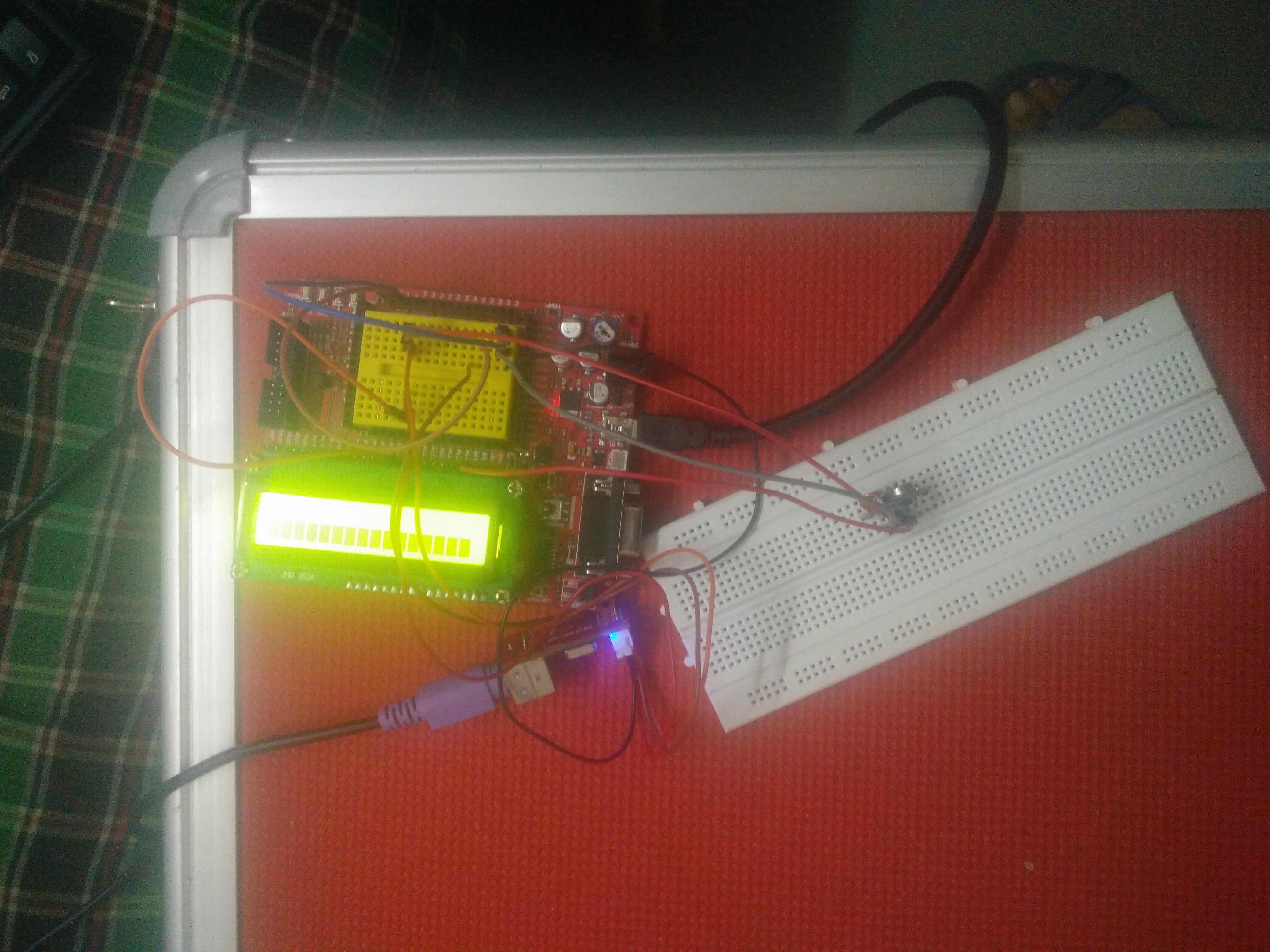
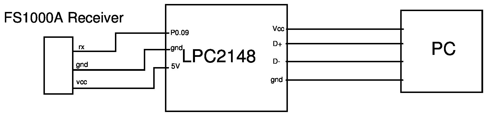
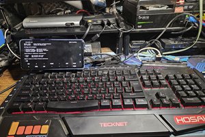
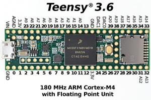
The project uses two LPC2148's to make a PS/2 keyboard function as a wireless keyboard. The PS/2 keyboard is interfaced to the transmitter LPC2148 using UART. The receiver LPC2148 is configured as a HID keyboard, which then sends this value to the PC via USB. A transmission and reception coding scheme is designed to reduce error probability, which arises due to noise at the transmission and reception terminals.
0%
0%
An RF Adapter to Make a PS2 Keyboard Wireless
Using FS1000A to communicate between a PS2 keyboard and Host PC
Become a Hackaday.io member
Already have an account? Log in.
Just one more thing
To make the experience fit your profile, pick a username and tell us what interests you.
Pick an awesome username
hackaday.io/
Your profile's URL: hackaday.io/username. Max 25 alphanumeric characters.
Pick a few interests
Projects that share your interests
People that share your interests

 Eric Woodward
 Emach00
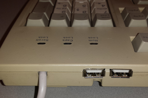
 sq7bti