 Dan Julio
Twelve-volt solar charging systems have a long history. Before charge controllers panels were connected directly to the battery through a blocking diode to prevent battery discharge by the panel at night. The panels were sized so that they could still put out enough voltage to charge the battery when dragged down to its potential. What we call "12V" solar panels are actually made up of 36 series cells which can put out an open-circuit voltage of 21-23 volts. There was no charge cycle and the panels had to be sized to the battery capacity so that a too-large panel wouldn't overcharge the battery. Often, and still today, smaller solar panels were used to provide float charges to keep unused batteries topped off.
Eventually relays and voltage comparators were added to chargers to prevent overcharging. As large scale solar power became feasible, more sophisticated charge controllers were developed along with better charge algorithms. The main types are PWM-based and MPPT controllers. They allow controlling the battery charge voltage enabling the Bulk, Absorption, Float charge algorithm that initially charges the battery to a higher voltage and then keeps it charged at the lower float voltage. MPPT controllers provide the additional capability of optimizing power output from the solar panel by controlling its output voltage. PWM controllers use a switching element like a P-Channel MOSFET to control the duty cycle the panel is connected to the battery to control its voltage. MPPT chargers use a controllable buck converter to also control the solar panel voltage to keep it at the maximum power output level (by measuring its output current and voltage). I wasn't able to find a history of PWM chargers but the first MPPT charge controller was apparently designed by an Australian named Stuart Watkinson.
My original idea for this charger was to implement a PWM version for two reasons. First, it is less expensive than a MPPT circuit and every penny counts for a tiny-scale American producer like myself. Second, for 12V systems there isn't a lot to be gained by using MPPT (the batteries and panels are fairly well matched). MPPT systems are much more idea for matching much higher-voltage panels to batteries.
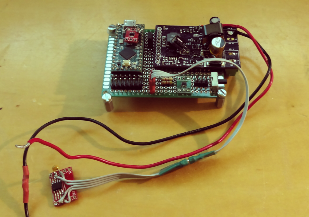
However as I played with an initial prototype that used a Teensy-LC as the controller, I became enticed by the idea that by adding an inductor, a diode and an output capacitor (plus more firmware), I could have a MPPT charger controller. The original PCB prototype had the PWM bypass P-channel MOSFET and driver, the ability to measure solar panel and battery voltage and current, a 3.3v supply for the Teensy and a 5V output converter. You can see an inductor, diode and some capacitors wedged onto it here. The 8-pin SOIC hanging off of it is an I2C-based temperature sensor (temperature compensation).
 The PWM charger really only needs to know the battery voltage although other measurements are useful . The MPPT charger also requires the solar panel voltage and current to compute the output power it optimizes. Battery current is not necessary but is of interest to determine efficiencies.
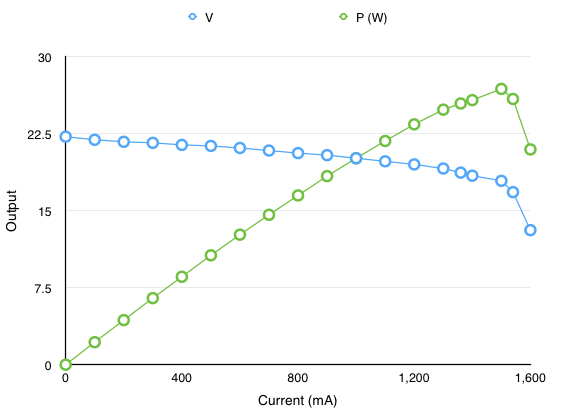
Implementing MPPT requires selection of an algorithm for keeping the solar panel output current at its maximum power output. The output of the algorithm controls the buck converter to keep the solar panel voltage at the point of maximum power. Using a programmable load one can see how a solar panel output changes with load current (this transfer function is also highly dependent on the amount of light). Below is the output of a 25W panel during a very sunny Colorado summer day. For this level of illumination the panel put out a maximum of 26.85W at 1.5A with the panel voltage at 17.9V.
Some time with google turned up the fact that there are a lot of very different MPPT algorithms, including some using techniques like fuzzy logic and swarm theory. Many requiring a lot of compute power which makes sense for a very large solar array producing KW or MW of power. Since I wanted to use a very cheap micro-controller I limited my testing to the traditional Perturb and Observe algorithm (P&O) and the Incremental Conductance algorithm (IC) since they use very simple decision logic at the expense of slightly less efficiency. Testing showed, for my system, the P&O algorithm worked as well as IC but requiring less computation. Ultimately I added some special case handling to the traditional P&O algorithm.
With a successful MPPT implementation I was faced with the decision of what type of system to use. As I mentioned earlier, MPPT technology adds a relatively modest improvement for 12V systems. The improvement is the additional power output of a solar panel working at its maximum power-point versus the power output when it's dragged down near the battery voltage minus the losses in both systems (buck converter efficiency in the MPPT system versus power lost in the PWM switching transistor). For the set of circuits (and transistors) I designed I saw a 10-15% benefit to the MPPT implementation. For example, one specific set of measurements with the same conditions yielded charge power of 8.73W for PWM and 9.76W for MPPT (11.8% increase for MPPT). MPPT is also better at eking power out of low light situations.
The main cost of MPPT is the inductor. Together all additional parts add about 20% to the cost of the BOM. I dithered for a while before making the decision for marketing reasons. Ultimately I figured that in 2018 people would want to see "MPPT" and the extra cost wouldn't be too bad. Sadly not a decision made for purely technical reasons. A perhaps ugly truth :-)
Efficiency of the MPPT version can be improved further by implementing a synchronous buck converter to reduce losses incurred by the diode. This requires replacing the diode with another MOSFET and more sophisticated driver circuit to control timing of the two transistors and prevent a catastrophic failure mode with one FET left on shorting the battery to ground (which will quickly destroy the FET). Although this would make a lot of sense in a larger charger, I decided that the additional cost wasn't worth the small improvement in performance for this circuit. Testing has shown that the current buck is around 90-91% efficient.
Although I don't expect the code to be of any direct use to anybody, I posted the final version of the two Teensy LC sketches (one for a PWM charger and one for the first functioning MPPT charger) and the original PWM test board schematic. Perhaps they are interesting to compare the relative complexity of the different approaches. They both drive LCD displays (first a 4-line display and then a 2-line display after I ruined the 4-line display from condensation while testing the system outdoors). As an aside, I think prototyping like this demonstrates the usefulness of the Arduino world. In my case the additional compute power of the Teensy LC was perfect for trying things out without having to worry about exceeding the capabilities of the micro.
Discussions
Become a Hackaday.io Member
Create an account to leave a comment. Already have an account? Log In.