 Dan Julio
A deep dive into the ADC measurements led to two firmware changes that have dramatically improved the system's accuracy.
- Storing the actual on-board reference voltage.
- Slightly jittering the ADC sample points over time.
The Silicon Labs EFM8SB1 micro-controller's built-in 1.65 volt reference has a fairly large specified operating range of 1.62 to 1.68 volts. I tested several parts and found that the reference did, in fact, vary from part to part. Without a known reference it would be impossible to get accurate measurements. I decided to add the ability to calibrate each board during manufacturing instead of adding a more precise external reference for cost reasons. Various internal calculations were already using a constant 1650 (mV) to compute voltage and current readings so it was easy enough to store the constant at the top of code space so that the programming fixture can load a custom value for each unit it programs (by changing, on-the-fly, the hex code that's programmed into the device). This means two different programs loaded, one to calibrate and then the real firmware with the calibrated reference voltage substituted for the default value of 1650. It took a slight bit of gymnastics to make the C-compiler place a constant at a specified location in code-space and there is a warning about a memory space overlap I can't seem to get rid of. The trick was to define a variable in code-space at a specific location for use by the calculations:
//-----------------------------------------------------------------------------
// Internal Reference Calibration value - stored at the top of code memory
// so a calibrated value can be loaded into the processor by a production
// programmer.
//-----------------------------------------------------------------------------
SI_SEG_CODE int16_t adcVRefMv _at_ 0x1FFD

...

// Compute a voltage reading in mV from the ADC raw count
//  mV = (ADC_COUNT * VREF * V_SF) / 4092
//
uint16_t _adc2mV(uint16_t adcVal)
{
    uint32_t t = (uint32_t) adcVal * adcVRefMv * V_SF;
    t = t / 4092;  // Max summed 12-bit ADC value is 4092

    return (t);
}
and then initialize code-space using an assembly language module in a different file.
CSEG AT 01FFDh
ADC_REF_VAL_HIGH: DB 06h
ADC_REF_VAL_LOW:  DB 6Fh
END
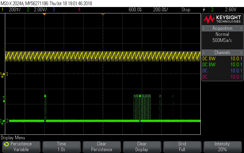
This change improved the accuracy of all measurements except the solar current (input into the MPPT Buck converter). This is because the delta current is large as the buck switching transistor is turned on and off (at 24 kHz). In addition both the PWM module generating the buck control signal and the timer generating the 4 kHz interrupt for the ADC sampling module are based on the same system clock. Each of the main analog signals (Vs, Is, Vb, and Ib) are sampled every four interrupts (minus occasional samples of the temperature sensors). The solar current, Is, was sampled about every 1 mSec and at the same place on the analog signal coming out of the current monitor as shown in the following scope trace. This lead to an error depending where on the analog waveform it sampled. The yellow trace is the output of the current sensor being sampled. The green trace is a diagnostic output set when the ADC is triggered for the Is reading and cleared when the ADC finishes the measurement (IRQ).

Since the ADC values were being filtered through a fairly slow software filter (140 sample rise time), an immediate solution seemed to be to jitter the ADC sample point slightly so that over time it would sample all positions of the input signal. This turned out to be fairly simple since the ADC was triggered by a timer IRQ. The timer IRQ just adjusts the next period by one time count up and then down within a range that covers the buck PWM period.
// Update the reload value to skew the period between samples
if (adcTimer0ReloadInc == 1) {
if (++adcTimer0Reload == _ADC_TH0_MAX) {
adcTimer0ReloadInc = 0;
}
} else {
if (--adcTimer0Reload == _ADC_TH0_MIN) {
adcTimer0ReloadInc = 1;
}
}
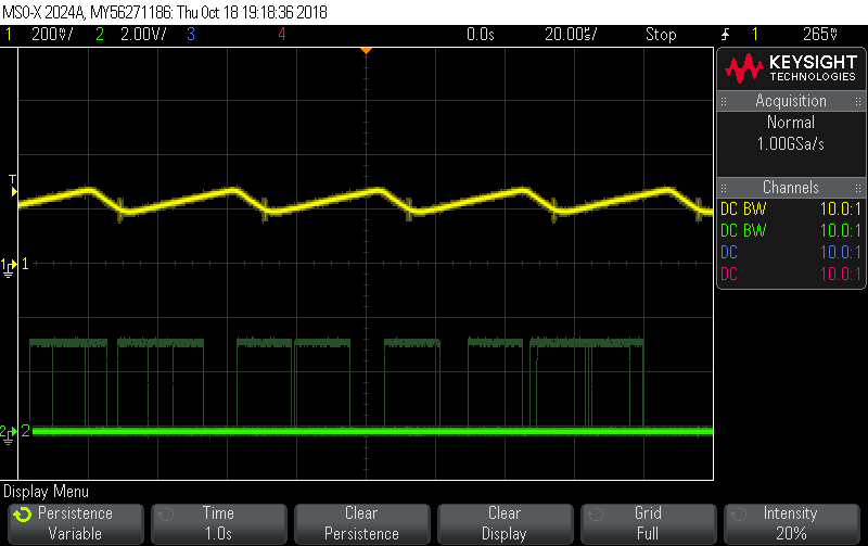
TH0 = adcTimer0Reload;Setting the scope to trigger on the ADC trigger and enabling persistence shows how the measurement jitters over time.
Or setting the trigger to the PWM signal and using several single captures summed using persistence.
Note that I am using a special ADC mode on the micro to create a 12-bit reading using four 10-bit conversions, each with a different reference voltage and combines them into a single result with a maximum value of 4092.
The result was a marked improvement in the accuracy of the Is reading with various measurement devices (DMM, external PSU and firmware) agreeing to within a few mA.
Discussions
Become a Hackaday.io Member
Create an account to leave a comment. Already have an account? Log In.