In this log I'll do another retrospective and write about how FATCATs sound engine works, and how it was developed.
Well, I guess "engine" might be a lofty term to use for it. Really it's a code chunk full of nested loops and if statements that cranks out an audio signal. It gets the job done, and it produces sound waves. Like an engine.
In the first log I wrote on this project, I discussed the 2016 prototype (I call it proto-FATCAT) that formed the basis for this project. In there, I mentioned how it "faked" having two separate sound channels (drums and base) by temporarily muting the base whenever a drum sound was playing.
For this project, that old sound engine needed to be rewritten from scratch. Since I now wanted to have three channels (drums, base and arp), "fake" channel mixing wouldn't cut it anymore.
I guess I'll start with an overview on how the FATCAT sound engine works currently. After that I'll write a bit about how I arrived at this specific solution, and some of the intermediary steps along the development process.
The top-down view
I'm going to take a top-down approach and start with a diagram on how the sound engine interacts with some other parts of the system.
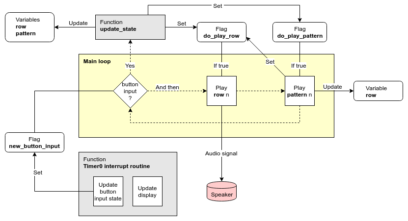
Diagram 1
On a conceptual level FATCAT has two main modes of operation: Song editing and playback. The point I'm trying to make with this diagram is that on the system level, there isn't much difference between them.
The timer interrupt routine executes about 10 times per second. It performs two tasks: One is to update the UI display elements to reflect the current system state. The other is to poll the button inputs and update their corresponding flags accordingly. If any button input is registered, the new_button_input flag is set.
If new_button_input has been set, main_loop will (eventually) call the function update_state. Depending on the current system state, the appropriate response to the button input is carried out.
After checking for button input, main loop carries on to the "Play row" stage. If do_play_row has been set by update_state, any instrument notes on the current song row will be played as a PWM audio signal. After that's done, do_play_row gets cleared.
Next is the "Play pattern" stage. If the corresponding flag has been set, the row variable will get incremented, and the do_play_row flag will be set once more. In such case, "Play row" will remain active on the next loop iteration.
When editing a song and changing rows with the Left and Right keys, only the do_play_row flag will get set by update_state. This allows the user to monitor exactly what the current row sounds like. And in essence, the only difference to actually playing the song is that in that case the do_play_pattern flag is also set.
The main loop
Note: The term "sample" is often used as a synonym to "sound file". In this text "sample" should be understood as being a discrete integer value as part of a digital sound signal.
Obviously Diagram 1 is a simplification of what's really going on. Also it's not 100% accurate. I'll explain how a bit further down.
In this next diagram I'm showing the main loop in a bit more detail.
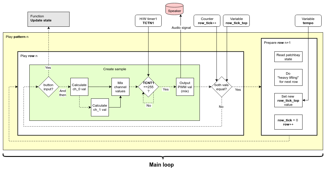
Diagram 2
Song playback consists of a couple of nested loops:
- The "Main loop" plays one row of the current pattern and then advances to the next.
- The "Play row" loop creates one sample, and then proceeds to create the next one. The progression of samples are streamed as a PWM signal to the speaker.
- The "Create sample" stage has an execution time 256 clock cycles. If the channel mixing task is completed prior to that, it will halt until all 256 clock cycles has passed, after which it outputs the mix to the audio signal.
To output the audio signal for an entire row, "Play row" has to iterate something like ten thousand times (depending on the song tempo). What wasn't shown in Diagram 1 is that the new_button_input flag gets checked every one of those times. This can seem wasteful, but it's necessary in order for the UI to remain responsive during song playback—especially at a low song tempo. Otherwise, system response to user input would be delayed until the current row finished playing.
Diagram 2 shows that there are only two sound channels, but FATCAT has three tracks right? So what's the deal? Well, keep reading and I'll get to that eventually.
A tight schedule
The wavetable synthesis that I use to produce instrument sounds requires a couple of things. FIrst there's a 16-bit value representing the frequency of a certain note. Then there's the actual wavetable, which in my case consists of an array of 256 8-bit values. Via a few extra steps the frequency variable will determine the number of increments by which wavetable array gets "sampled" into the audio stream, meaning that the same wavetable can be used to reproduce any note frequency. I'm not going to describe the process in any more detail here, but for anyone who's interested, I've followed the method described in chapter 13 of this book pretty closely.
Suffice it to say that a few clock cycles are needed for executing that task. On top of that there's also calculations required for the portamento effect of the base instrument, and for switching note frequencies in an arpeggio, and an assortment of other tasks.
All that stuff has to happen within the "Create sample" stage which, as mentioned previously, has a deadline of 256 clock cycles.
The final responsibility of "Create sample" lies in mixing the channels. That's another bunch of clock cycles. But I'll get back to that.
EDIT: It should be noted that whenever the timer0 interrupt routine gets called during playback, the "Create sample" stage will likely miss it's 256 clock cycle deadline for outputting the next sample. And if a button was pressed, additional deadlines will get missed since "Update state" gets called on top of that. But since these are relatively infrequent occurrences the actual musical output isn't noticeably affected. However—if you listen closely to a single sustained sine wave tone from the system, you will notice that it's not entirely "clean". I'm guessing that the missed deadlines are to blame for that.
What's the frequency, Kenneth?
In the initial stages of development, I guesstimated that it might be possible to perform all necessary calculations within a 256 clock cycle deadline. In this case the sampling frequency would be about 31 kHz. A deadline of 512 clock cycles would mean a sampling frequency of 16 kHz and so on. During the project design, I've usually tried to carefully weigh pros and cons of different solutions. But in this case I just decided to go with 31 kHz—consequences be damned.
Come to think of it, I'm still not sure to what degree a lower sampling frequency would affect the perceived sound quality. For some reason I actually never tested that.
Fake it to make it
(The third channel, that is.)
The sensible thing to do when designing for a system with three tracks is to dedicate one sound channel for each track. But my experience with proto-FATCAT had shown me that having drum sounds (with short decay) temporarily mute other instruments actually results in a pretty cool compression effect. Doing that would also save me one channel. During playback, on any row containing a drum, the instrument sounds would momentarily get replaced by the drum sound on both channels. Using both channels for drums would also allow for realtime mixing of drum patches using part noise, part wavetable; or the same wavetable played at different frequencies.
But alas, there was also the issue of having an open hihat sound. Now that's a long decay, spanning one or several consecutive rows. Any instrument notes on those rows would remain silent, and the illusion of having three independent channels would be gone.
Nevertheless I decided to press on with this solution, since I felt the pros of it outweighed the cons. I had to try figuring out a solution to the open hihat issue at a later point.
Fake mixing
Before deciding on going with a tried and true method for mixing the channels, I briefly considered trying some sort of time-sharing model. It would play just a few samples of channel 1, then switch to channel 2 an so forth and then back again. That way I could mix any number of channels at the same clock cycle cost. Also it would allow for easy balancing of individual track volumes by assigning more or less time to any given channel.
However I assumed there had to be a reason why no one used that method (as far as I know). It'd probably sound terrible. That would defeat the whole purpose with keeping with the 31 kHz sampling frequency in the first place. So I decided to not get overboard with outside-the-box thinking, and sensibly went with the method described below.
Proper mixing
Mixing two audio signals is as straight forward as it gets. Just arithmetically add the (signed integer) samples to each other. But now lets say the amplitude of your original signals is already maxed out. Then you'd also need to divide the result by the number of channels to avoid clipping. With two channels, that would result in each channel getting it's volume cut by half.
As discussed in previous logs, achieving a sound volume high enough was an issue, since the speaker has to be driven directly by the MCU. For that reason, playback using anything below maximum volume would be unacceptable.
When playing instruments on both channels, the combined volume would remain maxed out, even though the volume of individual instruments gets halved. That's fine. But what I didn't want was for the amplitude of an instrument to habitually get slashed, even with the other channel being idle. Basically I wanted a compression effect that guaranteed the total volume to remain at max at any given point during playback. That's simple enough in concept, I just needed a time effective algorithm for making it happen.
I searched the Web, and found this post on the "A Tasty Pixel" blog. It tackled basically the same problem, but the solution was a bit too elaborate to be useful as-is in my application. What I finally ended up with is sort-of a minimal variant of that, which still works as a means to the same end.
In my application, I had the advantage of having implemented a "duration" variable for each active instrument wavetable. Once row_tick exceeds an instruments "duration" variable, it should stop playing. I used that relationship for setting a flag for each channel, denoting whether the channel was "on" or "off", sound-wise.
It's really quite simple. Here's how the whole thing works:
(Some details slightly altered for clarity.)
uint8_t x = ch_0_duration < row_tick;
uint8_t y = ch_1_duration < row_tick;

/*HERE'S THE INTERESTING PART*/
int8_t signed_mix = ( ch_0_sample * x + ch_1_sample * y ) >> ( x & y );

uint8_t unsigned_mix = 128 + signed_mix;

/*WAIT HERE UNTIL 255'TH CLOCK CYCLE*/
while( !(TIFR1 & (1 << TOV1 )) ) {
} TIFR1 |= (1 << TOV1);

/*OUTPUT PWM SAMPLE TO SPEAKER TERMINALS*/
OCR1A = unsigned_mix;
OCR1B = unsigned_mix; /*INVERTED OUTPUT*/
On the "INTERESTING PART" row, the x and y variables serves two functions:
- When the allotted time for the current channel instrument ends, x / y turns 0 which mutes the corresponding channel in the mix.
- Whenever both x and y equals 1, the amplitude of the mix gets divided by two to avoid clipping (the bit-shift part). But whenever any channel is muted, no division takes place.
This way the desired compression effect is achieved with a minimum of overhead. The compression is strictly binary though–it's either on or off. But since there's no volume envelope for the instruments anyway, and the UI wouldn't easily allow for controlling such envelope even if it existed—then that's actually the exact right solution.
Now the same solution wouldn't work using three tracks. The MCU is terrible at dividing by anything other than powers of 2 (in which case the compiler substitutes it with bit-shift operations).
Fake it to make it
(The time limit, that is.)
This whole process really impressed on me how much, but also how little, work you can get done within 256 clock cycles. In this case the stress is definitely on the little part of that sentence.
So it was necessary to move everything that didn't need to be inside of the "Create sample" loop to someplace else. That "someplace else" is represented by the "Prepare row" step in Diagram 2. One example of this is the song data structures, which are optimized for size—not speed. So "Prepare row" pre-chews the song data for the next row into more digestible pieces for "Create sample" to swallow. And there's a lot other of stuff like that going on in there.
All that "heavy lifting" actually adds up to a few milliseconds worth of delay between every row being played. For the most part, that's not a problem at all. Only exception is when trying to sustain a single note over several rows. Such a note will get a small but noticeable hiccup in between each row. But hey—long sustained notes are just plain dull. They deserve to get ruined.
Don't break it
Now with a functioning sound engine in place, I started working on shoehorning in that open hihat feature.
The first solution I tried was to add a preliminary mixing stage:
On any row containing an open hihat, that sound would get mixed with the arp channel (called "ch_1" in Diagram 2). Then, ch_0 and ch_1 would merge in the final mixing stage. But in adding that step, I finally overstepped the invisible 256 clock cycle boundary. Any row playing both base and arp and the open hihat, ended up with instrument notes dropping a half-note or so in frequency. Unacceptable!
Another unacceptable issue was that the white noise hihat would completely overpower any arp notes, when using a 1 to 1 mix ratio.
So I had to try something else.
There's a time-share and place for everything
"Well, how about that half baked time-share-mixing idea from before? But this time, I'll just use it for mixing the arp and open hihat. That should require less clock cycles, and I can mix them by any ratio I please."
Well I did, and it worked great! Here's the pseudo-code:
(TCNT0 is the 8-bit timer counter register.)
switch( TCNT0 % 8 ) {
  case 0:
    if( flag_open_hihat_on )  {
      ch_1_sample = get_next_ohh_sample();
      break;
    }
  default:
    ch_1_sample = get_next_arp_sample();
}
It turned out a 7 to 1 mixing ratio gave a good balance between arp and open hihat.
Unsurprisingly, this mixing method did cause distortion. But the it wasn't noticeable with the arp, since it remained 87.5% unchanged. What's more, the hihat distortion actually turned out to be a positive. It introduced some "ring" and character to that original plain white noise. I liked it.
And with that, the sound engine was finally making all the beeps, boops and noises it was supposed to.
Note 1: In the text I write about using wavetables as a basis for generating instrument sounds. That's not entirely accurate. As a memory saving measure, certain instruments uses a simple algorithm, or simply random program data instead of wavetables. But since that's not of importance to the subject matter I glossed over that fact as to not get bogged down in details.
Note 2: Most variable names used in the diagrams and code snippets aren't the same as the ones I use in the actual code. In this text I tried to choose names that would make the most sense to someone who's not familiar with the source code and the naming convention I use there. On top of that, some of the names in the code are just confusing for no good reason at all.
Discussions
Become a Hackaday.io Member
Create an account to leave a comment. Already have an account? Log In.