My goal is this clone is 100% reverse compatible while adding some new functionality.
1. Built-in 63-key keyboard
2. 128kB RAM
3. Cartridge slot for new PROMs
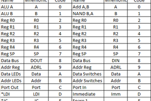
4. New instructions ST AC -> [X,D] and ST AC -> [X++,D]
5. Audio input
6. 4 Parallel inputs from DB9 connector
7. Hi-resolution mode (double screen width)
Much like the Apple 1 computer which did not come with a keyboard, the second generation did. This made the computer much more approachable to novices. I borrowed heavily from the mechanical keyboard culture to create a custom key layout using the Cherry MX key footprint.
The cartridge slot makes it possible to create cartridges much like the old Commodore 64 and Atari 400/800 style of computers. It also aids in development of new ROM code.
The new instructions make block memory copying easier. This is helpful for things like sprites or arrays of data.
The audio input can be used for old-school style program storage. With the advent of BASIC built-in on the ROM, support can be added for audio-out and audio-in data storage. Store your programs on your smartphone!
The Hi-resolution mode doubles the width resolution of the screen. This drops the color resolution to 3 bits, but could help significantly in BASIC program development.


 agp.cooper
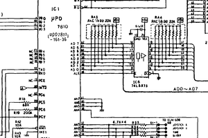
 mateusz.kolanski
 Hayden Kroepfl
 Colin Maykish
This should work better as a resolution doubler: http://www.ti.com/lit/ds/symlink/sn74ls298.pdf Drive it at 12.5 MHz. 6 bits in, twice 3 bits out. The spare flip-flop can divide the 12.5 MHz clock and feed the rest of the system. An it's own select line. Just hardwire it's multiplexer inputs to a 1 and 0.