 coon
coonMotivation
I am going to loose weight. Loosing weight takes time and can be very frustrating. Since I am a nerd and therefore interested in how electronics work, I was thinking about combining it with some hacking projects so beside improving my health, I have another reason to keep going.
At this moment I am logging my weight and my body fat values from time to time so I get on the scale and type the values from the screen by hand into a database. This is a bit annoying over time. It is not my first time that I try to loose weight but when I have learned one thing about loosing weight, than that you are trying to find excuses easily for not to log a meal, not to go to the gym etc. Finding excuses will get harder if the important tasks are comfortable and the hurdles are low.
Goal of the Project
The goal is very clear: I want to automate the process of weight logging. The first approach which came to my mind is to add a microcontroller which is equipped with an ethernet connection. This is then used to read the body values from the LCD screen of the scale and transmits them to a database over Ethernet automatically. Fortunately I am not the only person hwo has this idea in mind so due to a random talk with a cool guy called Akendo he joined me on that project and we started an initial hack weekend at c-base Berlin on 13th September 2018.
First Hack Weekend
We both brought our scales to find out how hackable they are. We didn't know nothing about how digital scales work so we just disassembled our scales and took a first look.
Day one - Analysing the AEG PW 5644 FA
First we opened my scale which is an AEG PW 5644 FA. I bought it for around 20€ on the web.
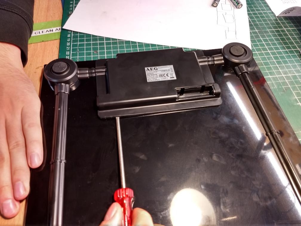
Since this scale consists of glass, the whole construction is glued together. After a while we managed to pry of the mainboard housing:
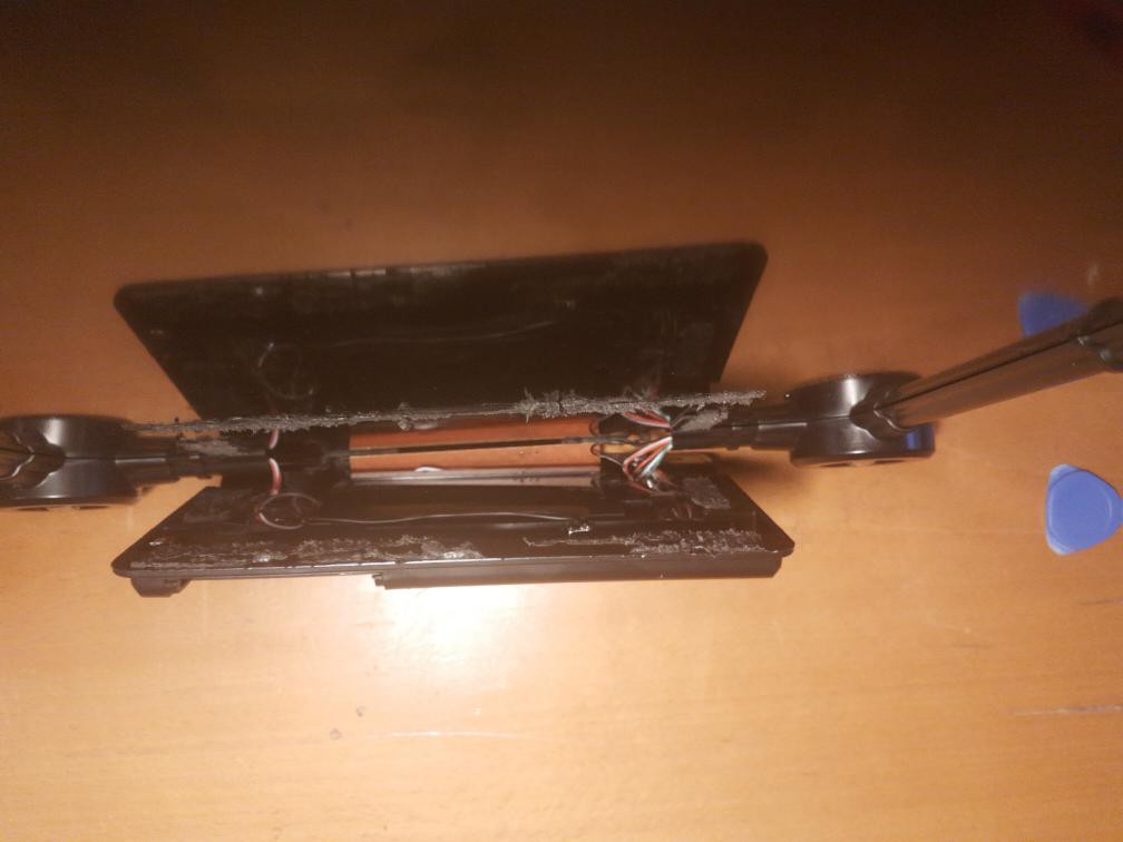
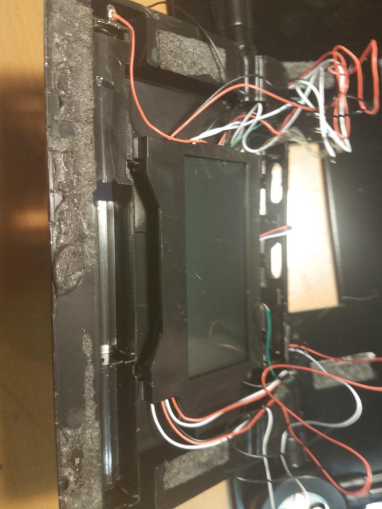
The housing holds, as expected, the LCD ...
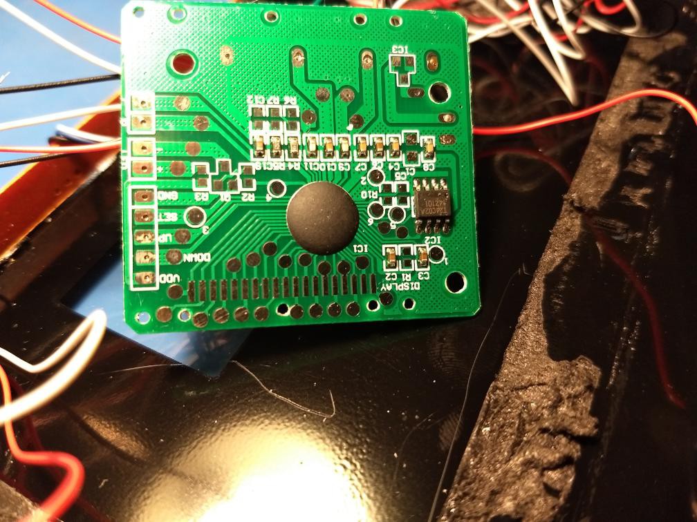
... and the mainboard. The main controller chip is covered by an epoxy resin blob. On the right hand side to the chip is an I2C 24C02A EEPROM which has a capacity of 2kBits (250 bytes). On the scale you are able to store up to 10 profiles which consists of gender, height and age. The scale uses this values to calculate things like your Body Mass Index or Basal Metabolic Rate. I didn't read out the chip yet but I will do later.
The LCD is using a so called Elastomeric Connector which is also referred as ZEBRA connector in literature (Purple thingy in the picture below). This connector has very fine seperated contacts which are pressed against the contacts of the mainboard and some very thin contacts on the glass of the LCD. You have to be very careful not to rip off the ZEBRA connector from the LCD since it may very hard to align the stripe to the conducting traces on the LCDs glass again:
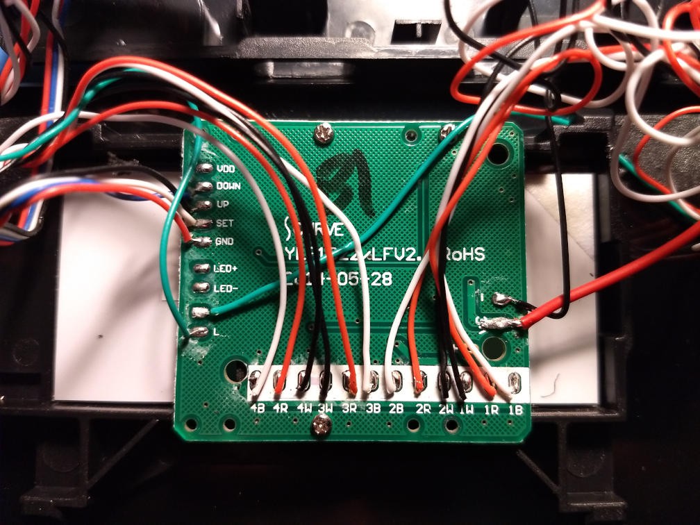
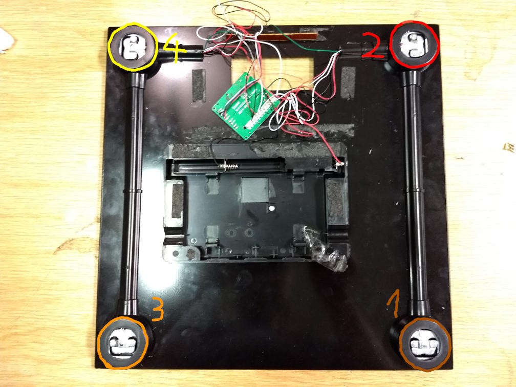
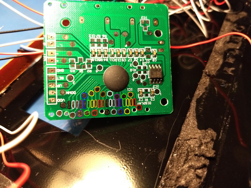
On the back side of the mainboard we find connectors which are going to the battery (red and black cable on the right hand side), the button panel (DOWN, UP, SET, GND), the load cell sensors (4B, 4R 4W, 3W, 3R, 3B, 2B, 2R, 2W, 1W, 1R, 1B) and the metal sensors for the bioimpedance analysis (L and R). Every gauge sensor is connected to three wires each. Interestingly there seems to be a mistake in the silkscreen. Assuming "B" means Black, "R" means red and "W" means white, black and white cables are swapped.
In the official manual the scale appears with a blue backlight. However, my scale doesen't have any but as you can see in the picture below there are unconnected LED pins on the left hand side so it meight be possible to add some backlight. I will also check this later:
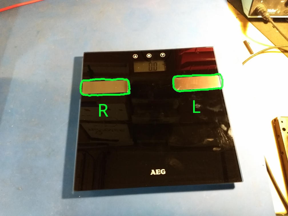
Wirings of bioimpedance contacts are also swapped:
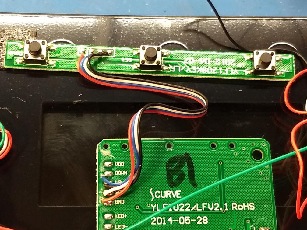
The buttons are connected like this:
The wirings to the load cell sensors are as following:
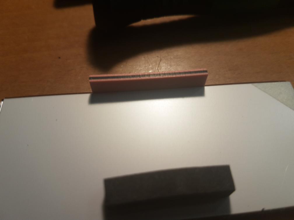
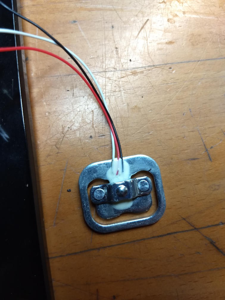
And this is how a load cell sensor looks like:
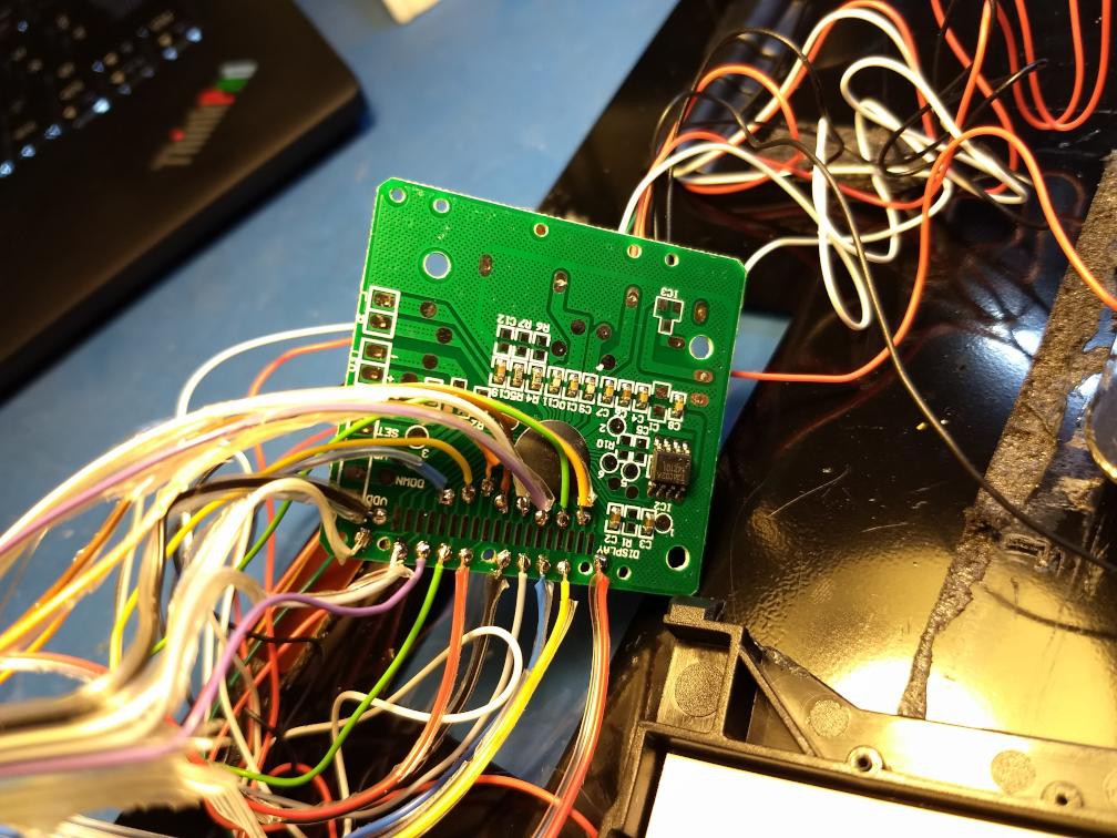
Allright, now we have a first overview. Opening the scale was a piece of cake. The goal is, as already mentioned before, to read the contents of the LCD. The LCD is proprietary, and there is no datasheet available in public, so the pinout has to be reverse engineered. Luckily there are test pads for all 19 pins of the LCD so the first attempt was soldering a rainbowcable on that testpoints, assembling the LCD again and watch the signals using a logic analyzer or an oscillosope:
After some minutes of soldering it now looks like this:
Unfortunately the display is showing garbage now, so something was broken on the scale. We ordered two additional AEG PW 5644 FA via Amazon prime evening express, so we can continue hacking on the next day.
Day Two - Find out what broke
The two new scales arrived in the evening so we used one of them to check what broke. Turns out, the display is still working correctly, so the main chip seems to be dead. I think it died due to the heat of the soldering so I have to be more careful on the next scale.
We still need to find out the pinout of the LCD. We tried finding VCC and GND using a multimeter but we had no luck. After a little google session we found some introduction in LCD technology:
And some very interesting instructables tutorial which does exactly what we want but using a kitchen scale:
https://www.instructables.com/id/Direct-Reading-of-LCD-Using-General-Purpose-IO/
There are two kinds of LCD: Static LCDs and multiplexed LCDs. Since the display has far more segments (more than 50) than pins (19) it must a multiplexed LCD screen. These kind of displays are a bit complicated to control.
So ne next steps are as follows:
- We have to solder the wires to the screen of one of the new scales again. But this time we have to be more careful with the heat, so the main chip gets not destroyed this time.
- We then reassemble the LCD and check the signals using an oszilloscope or logicanalyzer
- That way we need to find the COM pins
- We then have to implement an LCD driver circuit so we can find out which segment corresponds to which pins.
- After this is done we can finally read the screen in a machine readable way.
- When also this works, we are done!
Preparing next Hackweekend
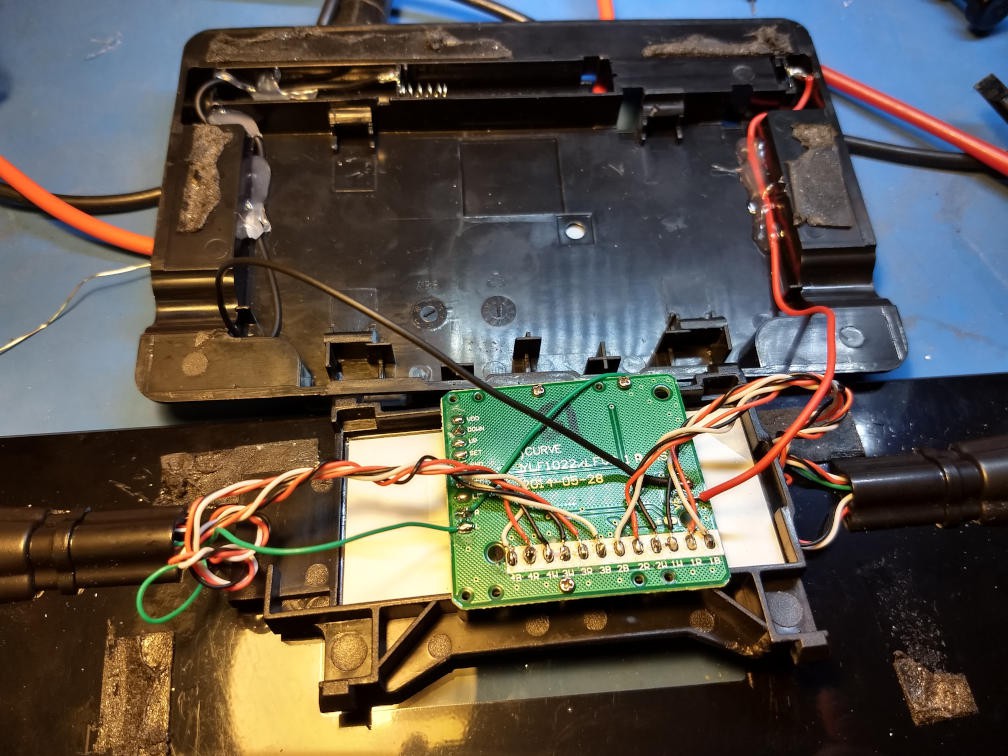
Since the cables rip off easily and some cables are unnecessarily long, I have shortend them a bit and did some kind of cable management so opening the case will be more convinient in the future:
To be continued...
TODO: Akendos scale description
TODO: add Images
Discussions
Become a Hackaday.io Member
Create an account to leave a comment. Already have an account? Log In.