Close
0%
0%

Hacking Nature’s Musicians

An artistic ecosystem of analog electronic sound generators

Similar projects worth following
Explore electricity in nature through artworks that sound like crickets, katydids, frogs, birds, and other non-human musicians. I don't use code or recordings, but old-school hardware and a power supply. In this project, I explain ways to portray various insects and how to randomize a natural chorus. I provide instructions for how to build your own piezo electric speaker in order to shape sound electrically and mechanically. These are techniques that I use to create electronic ecosystems that give nature-lovers insight into the spark of life, and urban dwellers an experience of the countryside.

Technically speaking, my project is an artistic survey of primitive-interface audio synthesizers for natural soundscapes. I'm focused on the nocturnal insects and birds of my rural landscape in Virginia, but enjoy the opportunity to study nature's circuits elsewhere in the world.

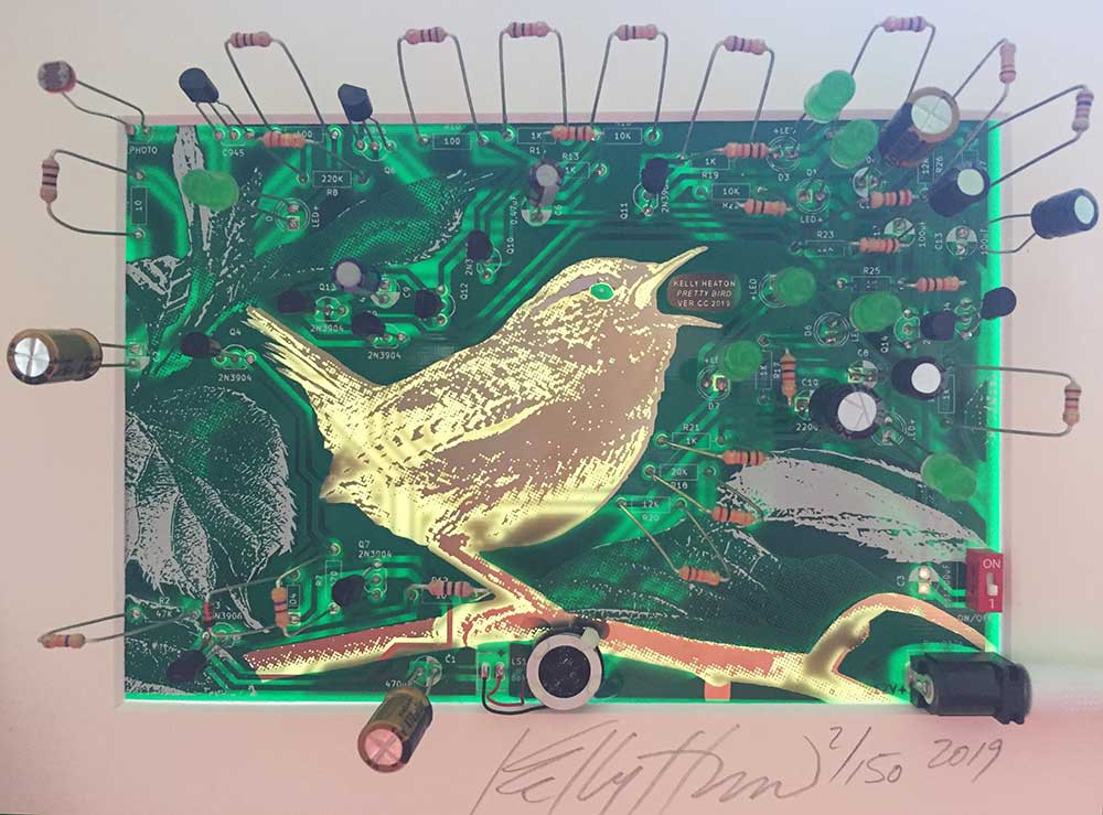
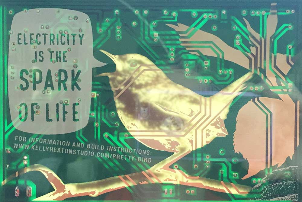
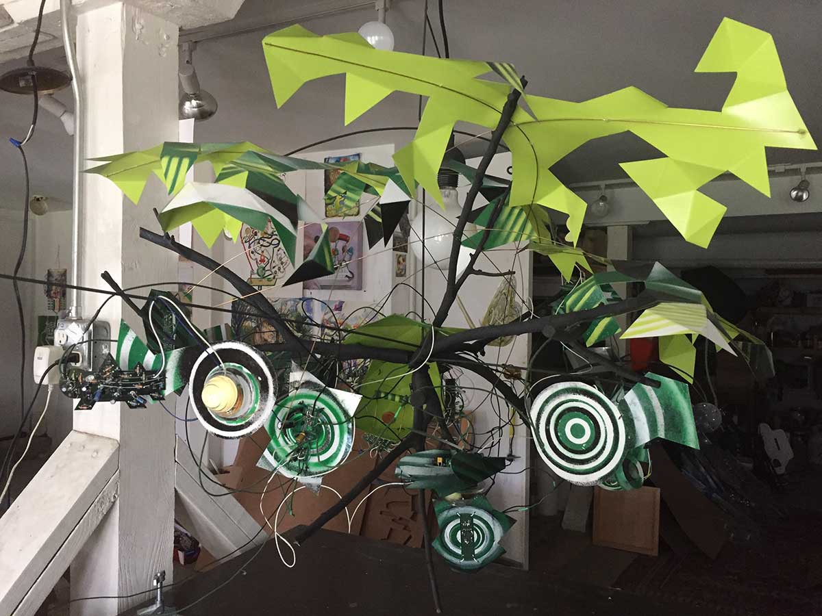
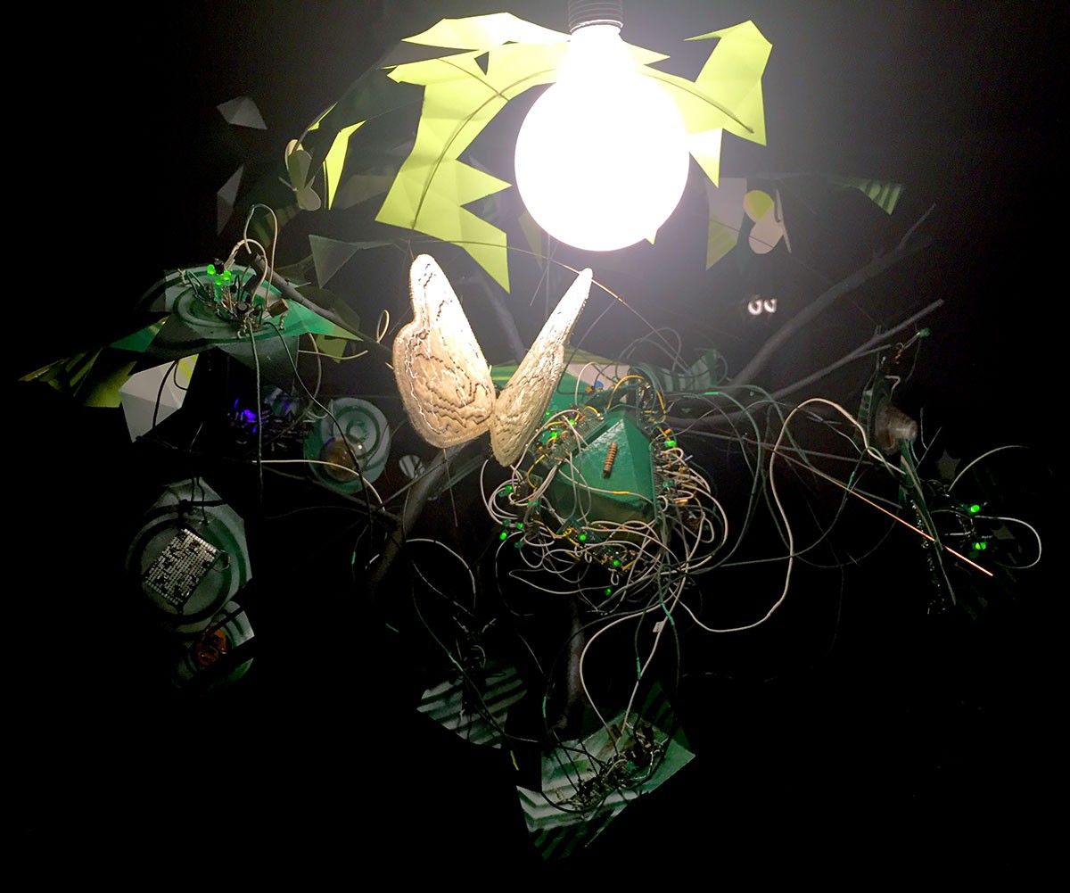
I am a visual artist who, in addition to painting and sculpting, works with the medium of electricity. My reasons are twofold: (1) I believe that electricity is the most important creative medium of our time and therefore paramount to contemporary artistic practice; and (2) I am fascinated by the spark of life in both biological organisms and manmade machines. Electricity has empowered humans to separate from nature in unprecedented ways, and yet electrical engineering gives us unparalleled insight into the nature of life on Earth. Through my art, I want to share my passion for electrical engineering and demonstrate its power to bring us closer to nature through understanding. I aim to reach a diverse audience, not limited to people with an engineering background.

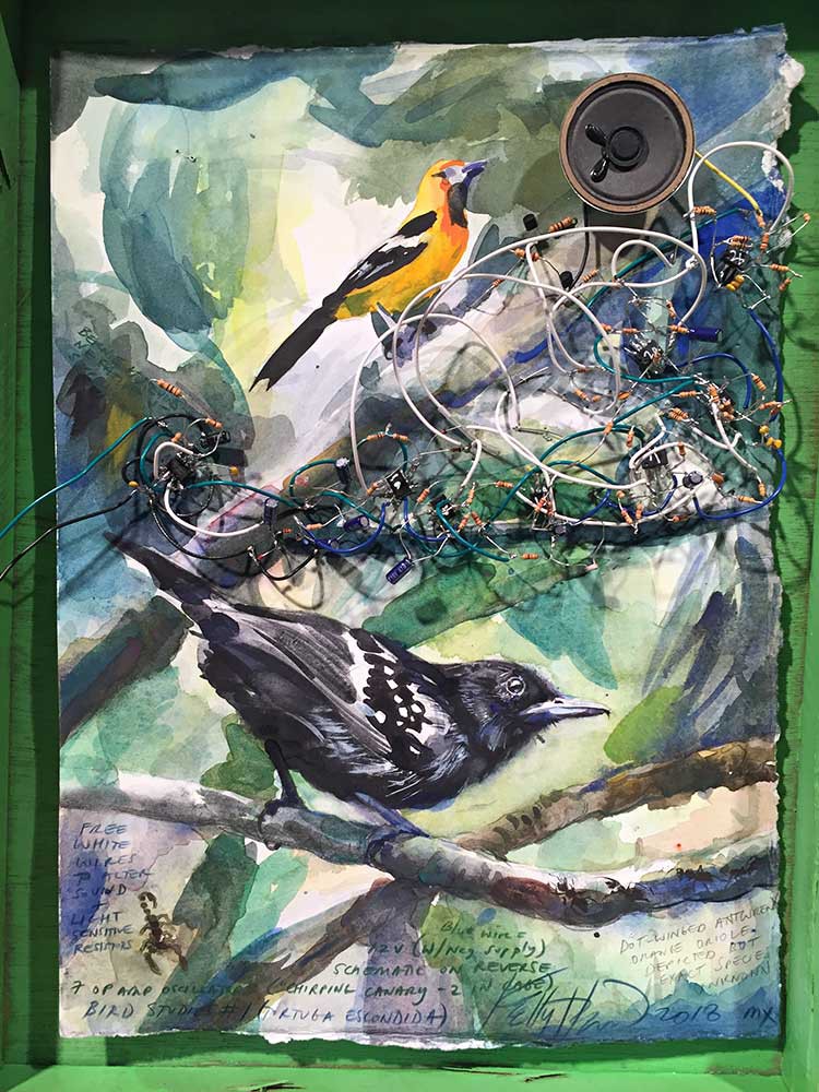
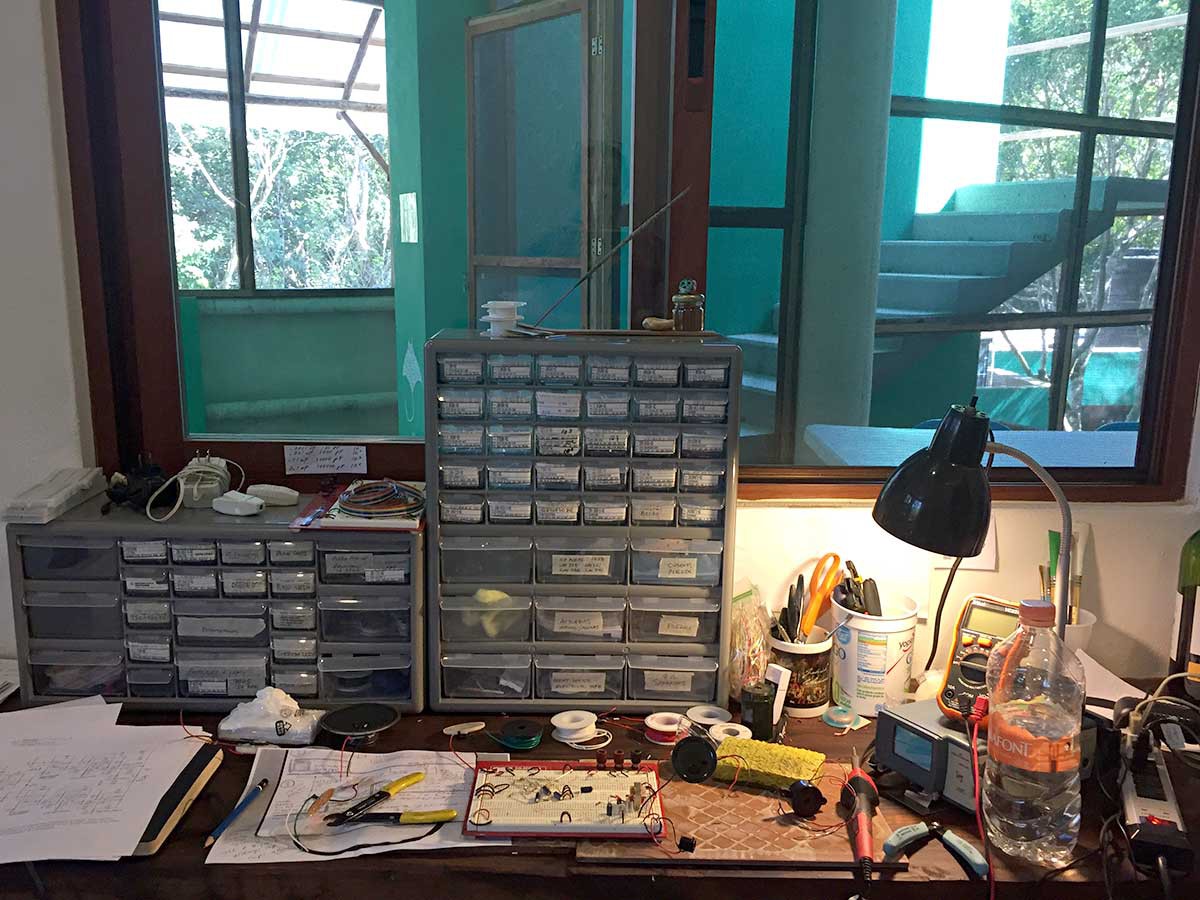
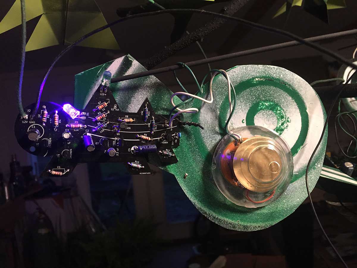
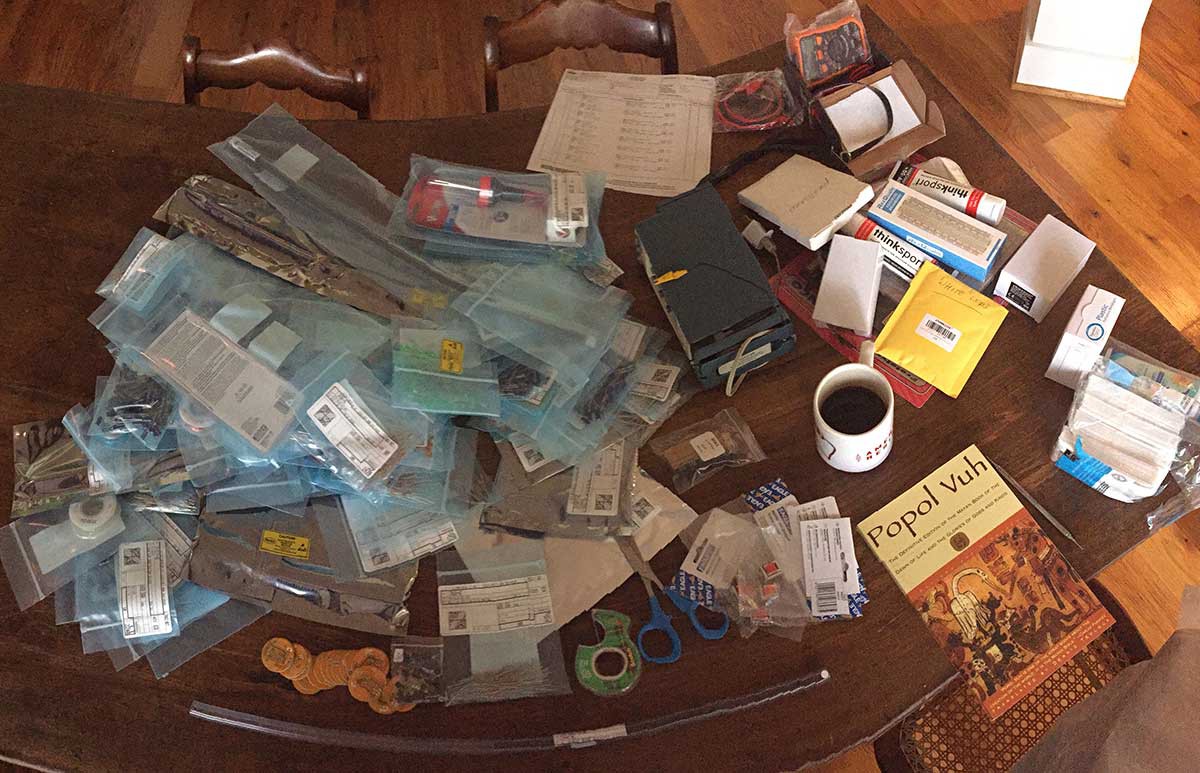
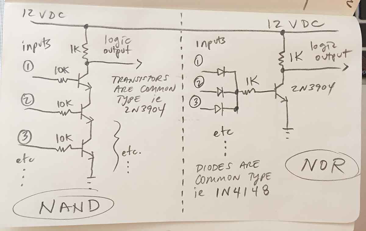
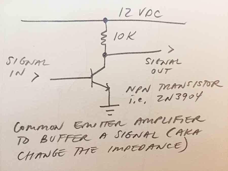
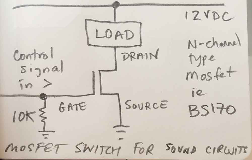
In this project, I do not use code or recordings to create sound --only hardware and a power supply. In today’s world of programmable logic and high-level interfaces, my return to 1970s-era technology might seem idiosyncratic, but to quote Forrest Mims III, “analog electronics parallels living organisms while programmable logic merely simulates life.” I use simple hardware because I want to gain insight into the transformation of electricity by physical components. Technical complexity makes it hard to understand what's actually happening. I would prefer to build these circuits using entirely discrete analog electronic components, to make the flow of electricity as explicit as possible, but I have found the cost to be prohibitive. 

This leads me to another important reason for my approach to electronic art-making: not only cost, but engineering complexity is a barrier for most artists. Electrical engineering has radically altered civilization but is not widely understood as a creative medium —certainly not by poets, artists, naturalists and other non-technical types of people. Most contemporary tools for electronic expression are high-level platforms with interfaces that distance the artist from a fundamental understanding of electricity. Of course we can use existing electronic devices to make art without any knowledge of electricity or engineering, but greater understanding of the medium yields deeper insight and a broader, more robust field of creative expression.

The circuits presented in this project are intended to delight with the recognizable sounds of nature, educate through design simplicity, empower with low-cost reproducibility, and inspire an appreciation for the art of electrical engineering.

Pretty_Bird_ver.CC-detail_sm.jpg

Detail of "Pretty Bird ver. CC" (2019), an artistic circuit board edition with an analog electronic chirp.

JPEG Image - 161.76 kB - 06/05/2019 at 16:06

Preview
Download

Pretty-Bird_CC_electronic-parts_web.jpg

Electronic parts to build "Pretty Bird ver. CC" (2019) edition of 150

JPEG Image - 154.24 kB - 05/31/2019 at 22:09

Preview
Download

Pretty Bird_CC_schematic.pdf

Schematic for my "Pretty Bird ver. CC" (2019) edition of 150

Adobe Portable Document Format - 57.08 kB - 05/31/2019 at 22:04

Preview
Download

bird-study-1_tortuga-escondida.jpg

Bird Study #1 (Tortuga Escondida), 2018. Analog electronics and watercolor on paper. The circuit is discussed in my log "More bird voice experiments." For video: https://vimeo.com/297499948

JPEG Image - 178.51 kB - 10/30/2018 at 20:41

Preview
Download

KHeaton_Bird_1.pdf

Basic, introductory "chirping canary" circuit based on Internet research, with my notes about ways to add variation in voice quality and tempo.

Adobe Portable Document Format - 42.21 kB - 10/25/2018 at 18:27

Preview
Download

View all 21 files

  • 1 × Breadboard(s) for prototyping Get several if you can (to prototype multiple circuits at once)
  • 1 × Oscilloscope Tool for looking at your waveforms. Mine is a Tektronix 465
  • 1 × 8-Bit Serial-In/Parallel-Out Shift Registers Such as CD74AC164E. Useful for linear feedback shift registers (pseudorandom pulse generation and cool patterns)
  • 1 × Decade counters (i.e. CD4017B) Optional: useful for cyclical pattern creation (but shift registers can do this, too)
  • 1 × Membership at your local Makerspace Use the laser cutter and vacuum former to make your piezo speaker case

View all 46 components

  • Analog oscillator bird circuits

    Kelly Heaton01/31/2020 at 13:59 0 comments

    I continue to prototype simple, analog oscillator circuits that create bird sounds. I'm fascinated by the simplicity and low-component count that is capable to generate pretty complex bird sounds. I have not yet generated songs with the complexity of, say, a mockingbird, but I assume that this could be done by adding oscillators.  Have a look:

  • Pretty Bird ver. CC

    Kelly Heaton05/31/2019 at 21:43 0 comments


    Pretty Bird ver. CC (2019) is an edition of 150 artistic printed circuit boards and associated parts that was commissioned by Creative Capital for their 20th anniversary retreat celebration. Creative Capital covered the cost of materials and I donated my time to realize the project. The printed circuit boards were manufactured by PCBWay in Shenzhen, China according to my specifications.

    The functional circuit design is based on my effort to electrically generate the “pretty bird” song made by a Carolina wren using simple, low-cost, and discrete hardware. The electronic behaviors (blinking lights, chirping bird) are caused by analog oscillations, which is to say, the waveforms are entirely generated by the discrete hardware and circuit traces that visibly surround the bird. No hidden software or recordings are involved. I would like to thank @DJ Mystic for providing me with a negistor oscillator circuit that I adapted for part of what you see here. I have uploaded my schematic and hope it will inspire the work of others in the Hackaday community.

    The central visual element of the board is a bird etched in exposed copper that has been electroplated with gold. The wren sits in a green and white forest defined by leaves and circuit traces. When the components are added, this forest effect is enhanced by the physical depth and texture that they create surrounding the bird. As you can see, I like to leave the component leads long because it makes the circuit appear "wild" and oddly natural. If you hold the circuit board up to a light, there is a watermark effect thanks to the translucency of the raw FR4 board substrate (versus the opacity of surrounding copper and solder mask).

    This work of art —a multiple— is complete regardless of whether the owner elects to assemble it, although soldering and electrifying the circuit manifests additional dimensions of the piece as shown in my video. The piece is designed to be framed and displayed dead or alive, with or without the components installed. Unlike many engineers, I accept that my circuits will eventually die from wear and tear because death is part of life -- and circuits are indeed alive in their own way. 

    As for framing, I used no glass on the front, but glass for the frame backer so you can see both sides of the circuit as well as the watermark. Bamboo is my frame of choice for this piece as it enhances the naturalist aesthetic and hints at the board's place of manufacture.

    HOW TO ASSEMBLE THE CIRCUIT

    Pretty Bird CC (2019) comes with the following electronic components (board reference in parentheses):

    Quantity 1: 0.47 uF electrolytic capacitor (C6)
    Quantity 4: 100 uF electrolytic capacitor (C8, C12, C13) *C3 is unused - leave empty
    Quantity 1: 220 uF electrolytic capacitor (C10)
    Quantity 1: 47 uF electrolytic capacitor (C9)
    Quantity 3: 470 uF electrolytic capacitor (C1, C2, C11)
    Quantity 1: 1N4148 general purpose signal diode (D4)
    Quantity 7: Green light emitting diode aka “LED” (D1, D2, D3, D6, D7, D8, D9)
    Quantity 1: 2x5.5MM power jack (J1)
    Quantity 1: 8 ohm speaker (LS1)
    Quantity 8: 2N3904 NPN transistor (Q4, Q7, Q9, Q11, Q12, Q13, Q14, Q15)
    Quantity 2: 2N3906 PNP transistor (Q3, Q10)
    Quantity 2: KSC945Y NPN transistor (Q2, Q6)
    Quantity 2: 10 ohm resistor (R1, R12)
    Quantity 2: 100 ohm resistor (R4, R10)
    Quantity 3: 12K ohm resistor (R20, R23, R26)
    Quantity 2: 10K ohm resistor (R16, R22)
    Quantity 8: 1K ohm resistor ((R13, R14, R17, R19, R21, R24, R25, R28)
    Quantity 2: 20K ohm resistor (R18, R27)
    Quantity 1: 220K ohm resistor (R8)
    Quantity 1: 470 ohm resistor (R7)
    Quantity 1: 47K ohm resistor (R2)
    Quantity 1: Light-dependent resistor (R3)
    Quantity 1: On/off slide switch (SW1)
    Quantity 1: 12 volt DC power supply with minimum 300 mA

    Extras: I made two small edits to the circuit after the boards were manufactured. These changes are not essential, but they do give a nicer chirp quality in my opinion. Scroll to the end of this...

    Read more »

  • Mexican Birds

    Kelly Heaton01/08/2019 at 02:45 0 comments

    I've been remiss in my project documentation since returning from Mexico's Yucatan peninsula (and end-of-year distractions).

    This post covers the bird studies that I built during my time at Tortuga Escondida near Akumal, Mexico. For my residency, I took a miniature version of my electronics workbench with me for five weeks of study in the jungle, where hacking supplies are not only unavailable but subject to failure due to fluctuating voltages, high humidity, sporadic connectivity, jungle wildlife, and mischievous Mayan spirits called "Aluxes." Electricity really is different in the rural Yucatan than most modernized parts of the United States. It was a fascinating albeit frustrating experience to build delicate circuits in such an uncertain environment, especially after my oscilloscope died from any number of mysterious causes. I'm not complaining, though -- it was one of the most memorable experiences of my life and gave me new appreciation for the complex relationships between electricity, nature, and culture. When I left, I donated my electronic supplies to the Akumal community center, hopefully inspiring some intrepid hackers in the pueblo. I plan to return.

    Back to my birds. I brought with me several printed schematics and data sheets as a point of departure, and these proved invaluable given my lack of a printer onsite (and unreliable Internet access). The schematics were all different strategies to produce simple, bird-like chirping sounds for novelty (like a doorbell that sounds like a squawking parrot). Here's an abbreviated list of the circuits that I tried while I was down there:

    Wilf's Bird Sound Generator. This BEAM circuit is an ingenious use of a hex inverter chip with effects that are fun to play with due to feedback. I built several different bird sounds with this as the basis, including my recent "singing mama" bird.

    Parrot Sound Generator. There are multiple circuits included on this page, but the parrot sound generator was the only one that really intrigued me. It uses a center-tapped transformer as well as an inductor (or one side of a second transformer) to create a chirping sound thanks to some cool physics. All circuits are thanks to physics, but here it's really obvious because you're basically listening to electricity flow through a coil. The easiest component to use for the non-center tapped coil is an inductor. Out of curiosity, I tested an old transformer that I found in Mexico and the results were intriguing. As you would imagine, it sounds "big" as compared with a smaller inductor.

    Bird chirp sound generator. This is the same principle as the previous parrot sound generator, but with a slightly different configuration. If you're curious about how the transformer and transistor work together to create sound, build both circuits -- it helps to have more than one view on the same principle. Here's video of this circuit in a piece I made years ago called "Restless Bird Chatters, Still Bird" (2018):

    Two canaries singing in a cage. This is a more complicated circuit, but you get two birds for your effort (albeit similar sounding). Is it worth it? The jury is still out for me. I used it to create my piece "Bird Study #1 (Tortuga Escondida)" (2018) but to be fair, the circuit got messed up when I soldered it (with my crappy soldering iron--never use a crappy soldering iron when you have a better option). So the following video is not a good demonstration of the circuit's proper effect. In fact, it's barely recognizable due to design changes and errors, but anyway, it's the basis for this piece: 

    I like the painting. Incidentally, people often ask me whether my nature studies are associated with particular species of animals (in the above case, a Dot-winged Antwren and Hooded Oriole). Of course I want my circuits to sound exactly like a species, but this almost never happens. I start with a sound and tweak it...

    Read more »

  • More bird voice experiments

    Kelly Heaton10/28/2018 at 00:29 2 comments

    I continue to explore circuits for bird song generation. I'm working my way through various schematics found on the Internet, testing them to hear how different parts and configurations sound. So far, most of the bird circuits I've built fall into the "chirping canary" or "depressive parrot" categories. Just prior to this log, I discovered another schematic to try -- and it's accompanied by a really helpful video by Mario Burriel Valencia aka @DJ Mystic  https://youtu.be/W69VaPoPoVo

    @DJ Mystic confirms what I have long suspected -- it's not only the shape of a waveform (sine, square, triangle, sawtooth, etc), or the component type (resistor, capacitor, transistor, etc), but the *specific make* of a component that can affect pitch, timbre, and loudness. This is especially true for transistors, and I have also seen variation in capacitors. ...Yes... I have read blogs by audiophiles discussing the pros and cons of specific parts for hi-fi equipment, but I didn't fully appreciate the importance of component specificity in low-cost sound generation. For some reason I assumed that since I work with cheap parts, the make wasn't that important. For example, I have thus-far thrown 2N3904 transistors at every problem they will solve. Now I realize the power of expanding my palette. Fortunately, I've got a friend coming down from the US and she's willing to bring a bag of electronics with her... so stay tuned for that excitement.

    As for progress in the past few days, I bit the bullet and breadboarded a circuit with op amps. My attitude may seem weird considering that most synthesizer enthusiasts live and breathe op amps... but the dual power supply annoys me (and I've never gotten interesting effects with single-supply op amps). Fortunately, some years ago, Bernie Hutchins gave me a useful schematic to convert voltage from a DC supply into a negative voltage of almost (not quite) the same magnitude. If you have a 12 volt supply, you can produce negative 9-10 volts using a 555 timer and a handful of components. Please see my files for this handy "Negative supply" circuit or read about it on Electronotes.

    The bird circuit that I built with op amps is described as "two canaries singing in a cage." You can find the schematic here: http://circuitos-de-electronica.blogspot.com/2007/10/canary-sound-simulator.html

    I substituted a bunch of LM741s for the LM324s because I don't like building in tight quarters. You can see the resulting circuit in this video, where the "two canaries" are in the breadboard in the foreground (a previously built "transformer canary" is in the background):

    I added some photocell resistors plus a few wires that you'll see me moving around (poor man's patch synth) to get variation in the circuit's behavior. It's pretty interesting, but maybe not worth the effort because there's a fair amount of complexity for sound effects that can be achieved with fewer parts. Still, I might make one of my electronic painting / sound studies with it because I like the aesthetic of crazy-complicated circuits.

    Last but not least, here's a short video of a different bird circuit (the transformer one discussed in my previous log and shown in the background of the "two canary" video). I tested various capacitors and it's pretty cool the realistic bird sounds that you can achieve with such a simple component swap.

    Still lots of work to be done.

  • New bird in town

    Kelly Heaton10/25/2018 at 21:06 2 comments

    I've temporarily relocated the physical form of Hacking Nature's Musicians to the other-worldly environment of Tortuga Escondida (near Akumal, Mexico) for a one-month fellowship on los musicos de la selva. Thankfully, my supplies made it through airport security and there's air conditioning to protect my electronic equipment against jungle humidity. Here's a photo of my bench showing a view of the jungle canopy and stairs to a roof deck with an amazing panorama over the electrically-charged ecosystem. (Giant scorpions occasionally grace my window screens but I have spared you that visual discomfort.)

    A few observations before I jump into the main content of this log: (1) Tortuga Escondida seriously resembles a research facility from the TV series Lost, so if I disappear you know what happened to me; and (2) the insects here are at least twice the size of their Virginian counterparts. Check out this insane Katydid!

    Amazing as the insects are, I'm not studying musical bugs because what's most remarkable to me --coming here from Virginia-- are the myriad species of birds. I've decided to see what I can do with the analog electrical engineering of bird song. 

    As a starting point, I built a version of the classic, "chirping canary" used in kitschy artificial nature scenes. Check out my files for an annotated version of this schematic, which is based on audio transformer oscillation. Basically, the surge in DC power that happens when you first turn the circuit on is capacitively coupled across the transformer and continues to fluctuate thanks to a transistor switch. If you change (or remove) certain capacitor values, the circuit stops oscillating and makes an unpleasant tone that can be very loud due to the current gain across the transformer.

    I've made a first informal video showing how the sound changes when different parts of the circuit are modified (apologies in advanced for some unpleasant beeps - don't wear headphones).

    Next, I built a few astable multivibrators and connected them to various aspects of the sound-generating circuit in order to make the chirp sound more like a bird song. Some of my tests are documented in a second video:

    Watch the green LEDs (and follow the white wires) to get a sense for what the astable multivibrators are doing. 

    Birds are very clever singer-songwriters, so it's going to take a lot more work on tempo and pitch variation to get interesting songs. I plan to try numerous strategies to generate voice quality because I want to build a jungle of different bird circuits ranging from sparrows to whippoorwills to parrots to owls to a Resplendent Quetzal, relative of the legendary Mayan Plumed Serpent. If you have suggestions for circuits to try, I would be grateful.

    So... not only do my bird electronics need work, I could use a new "avian speaker" design. It seems that piezo buzzers are better suited to insects, while 8 ohm speakers have higher bird fidelity. Initially, this observation puzzled me (and I'm still not clear) but I got some useful clues from the ingenious musician, Nicolas Bras. It's material physics: the thin, metal vibrations of a piezo disk have more in common with the chitin instrumentation of an invertebrate than the fleshy air bladder and vocal chords of a squawking bird. Some insects do force air through a membrane, like living kazoos, but crickets rely heavily on the idiophonic effects of leg or wing rubbing. The sound made by an idiophone is quite different than that of an aerophone or membranophone, like hitting a cymbal versus blowing through a reed, the latter of which happens when a bird forces air through its vocal cords. I searched the web for homemade instruments that behave like an aerophone with a membrane and found this cool "membranophone" video by tachionics. 

    As I did with my "insect-like" piezo, I'd like to build an electronically actuated speaker that has material properties more in common with a bird. I've got various 8 ohm speakers that...

    Read more »

  • Electrolier (September night in Virginia)

    Kelly Heaton10/20/2018 at 18:30 4 comments

    I've been working around the clock to finish my Hackaday Prize application and pack for Hacking Nature's Musicians in Mexico. As closure for my recent chapter, the various circuits that I've shown you over the past few weeks have migrated from my bench and into a sculpture titled "Electrolier (September night in Virginia)," 2018. Here is an informal video:

    The video quality isn't great... (shot with my iPhone under bad lighting and extremely messy studio)... but hopefully you get the idea (see second video below). The sculpture contains one instance of my Mother Nature board design, recognizable by the dense tangle of white wires connecting logic gates, and six sound generating "animal circuits" each with its own speaker. The colorful graphics are spray painted cardboard, and everything is hung on a tree structure under a moon (globe pendant bulb). Oh, and that large moth is made out of silk velvet that I dyed and embroidered with an old industrial "Ultramatic" machine. I would have used small molex-style connectors to connect everything, but there was just no time.

    It's interesting that so many long wires didn't screw up my signals. I credit this to my use of common emitter amplifiers to buffer the signals, and the fact that I'm not drawing much current for anything you see (or hear). The whole sculpture is powered with a 12VDC / 1.5 amp power supply. I also used multiple 0.1 uF ceramic capacitors between power and ground on most of the individual perfboards. It's critical to remember power-ground capacitors when you're dealing with a lot of amplified signals banging on your power rails. I'm careful to avoid really small gauge wire, and I add many pathways to ground ("let ground abound.")

    So... now I am packing my electronics bench into a suitcase and praying that security does not detain me at the airport. I'm throwing in packets of desiccant and crossing my fingers that jungle humidity doesn't zap everything. Making analog electronic circuits in the jungle will be interesting to say the least -- stay tuned for the sounds of los músicos de la naturaleza en Quintana Roo!

  • Mother Nature in perfboard (+more tips)

    Kelly Heaton10/15/2018 at 22:49 0 comments

    I've been busy migrating my "Mother Nature" controller circuit out of my breadboard and into perfboard... and yes, it's insane but no, I don't have time to produce a printed circuit board because I'm leaving in six days for a fellowship in Mexico. For the record, I do not recommend soldering so many components and connections in perfboard because the risk of error is high, either from bad solder joints, signal interference, or just plain confusion. I plan to design a printed circuit board for future embodiments of Mother Nature. Stay tuned.

    As you can see in my previous log, I'm surrounding my perfboard circuits with spray painted cardboard to make them look cool -- and by the way, you could use this quick-and-dirty strategy to make a "starving artist's badge" for the Hackday Superconference.

    As for the design of my "Mother Nature Board," aka random pulse generator to trigger various events, I have some additional technical tips to share:

    • Don't have logic ICs on hand? Build discrete transistor gates. This approach has the advantage of common components (NPN transistors, resistors, diodes) and you can add multiple inputs to the same gate -- which is useful if you discover that an event is triggering too often... just add another input to the gate and the outcome will become less frequent. Not triggering often enough? Remove or change an input to the gate. You can even tie an input to ground (or power) and let the other fluctuate. I use 2N3904 transistors for as many things as possible, but you could also build these cool light gates described by @Dr. Cockroach 
    • There's a limit to how many things you can drive directly with a signal such as the output of a logic gate. Good engineers read data sheets and calculate voltages and current at various locations in their circuit. Impatient engineers add a generic common emitter amplifier between the signal OUT from a logic device and the signal IN to whatever you're driving. This hand-waving approach to buffering will not work in all cases! But it will probably work for most slow logic applications where you want to transform a signal multiple times and drive some light loads. I'm an artist who prefers prototyping to math, so I work a lot with "try it and see" circuit design. Plus, I am not building a nuclear reactor. Note that a common emitter amplifier will invert your signal. Pay attention to whether you need your signal to be active high or active low. Note that a 555 timer in monostable aka one-shot configuration is looking for an active low input. If necessary, invert the signal again to get what you need.
    • Mosfets make great electrical "on/off" switches because they don't draw current on their gate (==the mosfet equivalent of a transistor's base). They just need a voltage. I use mosfets for the last step in my Mother Nature circuit, or the point at which I want to turn power on or off to a particular sound circuit (the load). Make sure you have a gate resistor to ground or voltage will "sit" on the gate even when the signal is low (and the mosfet won't turn off).

    I hope these tips are helpful. To end this log, I give you a video showing my Mother Nature circuit in perfboard with two sound circuits hooked up. If you watch the LEDs carefully, you will see how certain combinations of logic are triggering the sound circuits. The cricket is wired up to chirp most of the time, whereas the Katydid is triggered less frequently. For this demo, I hooked up only two sound circuits because it's already hard to understand what is happening, and more circuits becomes a sort of natural chaos... which is my goal, as you will see in forthcoming logs.

  • One signal, many sounds

    Kelly Heaton10/11/2018 at 20:39 0 comments

    I've been migrating my circuits out of the breadboard and into soldered form. I'm also hooking up speakers so that my sound generating circuits are ready for installation in a sculpture of Virginia's nocturnal ecosystem. Because most of my circuits use a custom piezo electric speaker (built with my own amplifier board), I have to install each piezo element into a physical housing... and there's some interesting "play" here. One electronic signal can generate many different sounds depending upon the speaker's physical design. Here's a video of me testing various installations of a piezo element for an insect that makes a steady background noise.

    It's cool to experiment with the interface between electrical signal and material properties. It's also critical to get it right, or else the piezo element will make a horrible rattling or screeching. Even a tiny drop of glue (to fix the piezo element in place) will alter the sound quality --usually the pitch-- and superglue can sound different from rubber cement or hot glue or tape. All of this is no news to a human musician, who knows that a note ill-played (even slightly) is a fail, and teensy subtleties often make the difference between average sound quality and genius.

    It is interesting to wonder what makes animals of the same species sound different in nature: is it their electrical impulse or their physical form? (Is it their schematic, their CAD file, or their bill of materials?) Members of the same species inherit the same circuit design as well as physique. External physical factors, such as climate, have some degree of influence over material properties of the body --for example, a dehydrated cricket sounds differently than the same cricket wet with rain; a fat frog sings a different tune than the same frog skinny; and so on and so forth. We also know that "animal circuits" are sensitive to electromagnetic fields, and capacitive coupling undoubtedly affects individuals in close proximity. I suspect that physical factors play a greater role in the variability of an individual's song if but for no other reason because birds sound the same whether they are sitting on a tree branch or an electrical transformer (at least, I think they do). PS: Eventually I will tackle the challenge of bird song, but their vocal complexity requires more computation... which is why I have started with insects.

    To end this log, I leave you with one more video clip of my "background noise" insect. Here it is with a plastic spool installed over the piezo (now painted green, black, and white). The soldered perfboard is embedded in a cardboard cutout that is painted to look like a forest creature sounds. Soon, this mixed media object will be joined with other embellished animal circuits to build a vignette of nocturnal musicians.

  • A musical composition

    Kelly Heaton10/05/2018 at 01:05 0 comments

    While my project is far from over, I'd like to recap what I've covered thus far and offer you a little musical composition. As evidenced by this video, most of my circuit designs have yet to leave the breadboard -- that is work for the coming weeks (and months, as I layout many different artistic PCB designs for sculptural ecosystems). Still, you can see the following ideas that I've discussed in previous logs:

    -- a variety of "animal circuits," aka analog electronic sound generators inspired by the nocturnal soundscape of rural Virginia

    -- "Mother Nature Board," aka a discrete component random pulse generator for naturalistic sequencing of animal circuits

    -- home-brewed piezo electric speakers, including some hacks like stuffing cotton into the speaker housing to muffle the sound

    -- a painterly frog with a croaking circuit built in

    I hope you've enjoyed my content thus far. Stay tuned for updates as I build a sculptural "electrolier" of the night in rural Virginia, as well as entirely new animal circuits based on my experience of the Mayan jungle. I've launched a GoFundMe campaign to finance electronic supplies for hacking nature's musicians in Akumal, Mexico. If you're interested to support me in this endeavor, please visit gofundme.com/hacking-nature039s-musicians-mexico Thanks so much!

  • Mother Nature Board (aka how to conduct a natural chorus)

    Kelly Heaton10/05/2018 at 00:25 2 comments

    The question of how to conduct a chorus of nature's musicians is perplexing because humans aren't in charge --Mother Nature is. The idea of physically "playing" a cricket or other musical animal is compelling, but I'll leave that (cruelty-free) implementation to someone who knows how to play an instrument.

    My approach is to let Mother Nature conduct her own, which is to say, allow a circuit to control an electronic chorus. What I want is an autonomous master sequencer that runs indefinitely, controlling the noise of multiple animal circuits in a seemingly random way, but never so abhorrent as to be unbelievable. My control circuit doesn't have to be truly random according to cryptologists, but it does need to be unpredictable for the average observer. Otherwise, listeners will detect a pattern and the effect will be unconvincing if not downright annoying.

    The key to my solution is a circuit designed by Charles Platt called "Really, Really Random Number Generator" that was published in Make Magazine in May, 2015. Platt combines a white noise generator (a source of true randomness) with a Schmitt inverter and shift register to produce a never-ending sequence of random bits --eight bits, to be precise, as that is the output of the shift register in his design. I encourage you to read his article and study his schematic, as he does an excellent job of explaining the design principles and I am only standing on his shoulders (as in "standing on the shoulders of giants"). 

    If you refer to my schematic "Mother Nature Board (random pulse gen).pdf" included in my project files, you will see that Platt's design makes up the lion's share of what I'm doing to simulate Mother Nature's timing. I made a few changes to his circuit because I am running at 12V instead of 18V, and I use a larger capacitor for the Schmitt oscillator because I want a slower clock for my shift register in order to see the state changes (plus, this is how I get so many bonus fireflies and other LED eye candy). The remainder of my schematic comprises two basic functions: logic gates to generate further random pulses, some of which occur less frequently than the states of the shift register; and a collection of 555 timers in monostable configuration, aka "one-shots" to generate pulses of longer duration. 

    Ultimately, it is the outputs of the one-shot timers that I want. These pulses are how I turn animal circuits on and off (or affect some other parameter). Platt's design is a starting point for me to control any number of animal circuits: an output of his random number generator (and logic gates, as desired) acts as a trigger for a one-shot. More frequent triggering equals more pulse out. The duration of a one-shot's pulse out is a factor of the resistor and capacitor on DIS and THR of the 555 timer. You have to breadboard the circuit and mess around with it until you get the frequency of triggers and pulse durations to your satisfaction. It's not hard, but I give you the following hints/ warnings:

    -- The circuit is sensitive to noise.

    -- Not all 2N3904 transistors are made the same, and you must get the right one for the noise generating part of Platt's circuit. I tested multiples from my collection and some worked, while others did not. If your shift register isn't shifting, it's probably a problem with the noise generator.

    -- The trigger into the 555 monostable (one-shot) is active low. You can use leftover inverters in the hex Schmitt IC or build your own, as needed.

    -- Careful about impedance. The logic ICs can't drive much of a load, so you might need to add a transistor switch in-between (especially when you want one output to control multiple things). This also applies to the output of the one-shots.

    Last but not least, here is a video without sound that is intended to show the different elements of my Mother Nature Board. Pay attention to the LEDs: they reveal how the states are changing at various points in the circuit.

    “The...

    Read more »

View all 15 project logs

  • 1
    How to make your own piezo speaker / buzzer

    Get your parts. You need a raw "piezo with feedback" disk element that is rated for 2.8 KHz frequency. (These instructions will work for 2.7 KHz - 3.5 KHz.) The important thing is be sure that your piezo has feedback (MFG). Digikey sells them, and I've also bought some on eBay. 

    You will also need the following electronic components (all through-hole):

    -- One each of 330 ohm, 1.5K, and 220K carbon film resistors

    -- One BC547 transistor

    -- 22 gauge (or less) wire in three colors (corresponding to MFG of the piezo).

    -- Soldering equipment

    Manufacture your circuit board. You can either work from my schematic ("Piezo_amplifier2") or send my Gerber files to a manufacturer. The files you need are uploaded to this project. If you're unsure about my circuit, then breadboard it first.

    Solder your board. Be careful soldering to the piezo disk - they are delicate. Avoid stiff wire for this part. Give yourself enough length that you can position the piezo but not so much that you have extra bulk. Unless you are adding an optional resistor to my amplifier board (see R4) --and you probably aren't-- then put a jumper to ground here. Give yourself longer wires on "input" and "GND" so you have something to work with. These are where you will connect to the audio signal and common ground of whatever circuit is generating your sound.

    Make a speaker housing. I show a example housing on my blog that I vacuum formed out of 0.08" acrylic and laser cut to a round shape with a backing. You can also make something quick and dirty out of cardboard or scrap plastic. The amplified piezo will make sound without the housing (but it won't be as loud and the sound will be thinner.)

    Put your piezo and circuit board in a housing. Careful when you bend the piezo wires and don't let the components cause a short circuit. You might want to stick a thin piece of non-conductive material between the board and the piezo disk, but remember that anything touching the piezo will likely change its sound quality. You can play with this, too, by stuffing non-conductive materials into the housing - like cotton or foam. I've tried affixing the piezo disk to the housing with a short piece of plastic tubing superglued to the center. That works well. Play around with it until you get the sound quality that you like.

    Connect your speaker to a low voltage audio signal and common ground. By low voltage I mean like 6-12 volts. It might work with higher voltage but I haven't tested it. I will add of couple of animal circuits to this project that you can build to generate the audio signal.

  • 2
    How to make a chirping cricket from discrete transistors

    Get my schematic. Download my project file "Heaton_transistor cricket.jpg."

    Get the following equipment (skip this step if you're an experienced hacker):

    -- 12 volt DC power supply (a 9 volt battery will work if that's what you've got)

    -- Breadboard (then solder freeform, or in perfboard, or make a printed circuit board...or build your circuit into paper or fabric or whatever if you're crazy like me)

    -- 22 gauge solid hook-up wire, wire strippers, flush wire cutters (and solder + iron if you decide to make your cricket permanent)

    -- Some way to connect power to your breadboard. I use a 12 volt DC "wall wart" power supply with a 5.5 x 2.1 mm male plug, and I connect it to my breadboard using a mating female barrel power jack that has 22 gauge wire leads soldered on... remember, most power supplies are "center positive" but always good to check...)

    -- Optional: a multimeter and oscilloscope, especially the oscilloscope will enable you to look at the chirp waveform

    Get the following parts:

    5 :: 2N3904 transistors

    1 :: 2N3906 transistor

    3 :: 1K carbon film resistors

    1 :: 4.7K carbon film resistor

    3 :: 10K carbon film resistors

    4 :: 12K carbon film resistors

    1 :: 220K carbon film resistor

    1 :: 0.1 uF ceramic capacitor

    2 :: 2.2 uF electrolytic capacitor

    1 :: 4.7 uF electrolytic capacitor

    1 :: 47 uF electrolytic capacitor

    1 :: 100 uF electrolytic capacitor

    1 :: Piezo electric speaker (buzzer) that is responsive in the 2.8 KHz range

    Optional parts:

    2 :: LEDs

    +1 :: 10K carbon film resistor

    1 :: 30K carbon film resistor

    Other resistor and electrolytic capacitor values to play with, maybe some variable resistors (potentiometers) if you want a cricket that is easy to adjust

    Other piezo electric speakers to play with (i.e., piezo elements that are sensitive at other frequencies, or speakers with a different physical housing). You can try 8 ohm speakers (and should for insight) but I doubt you'll like the sound if "cricket" is your aim.

    Extra components (especially transistors) if you intend to tweak the circuit because you might fry something.

    Build a cricket according to my schematic.

    Happy chirping!

  • 3
    How to draw if you have no artistic talent

    Use a tracing projector!

    A lot of people will argue that this method is cheating --to which I say, cheating who? Andy Warhol regularly traced his images, as have many other artists throughout history. 

    There's more than one way to do this, but here's a set-up that I like:

    -- On your computer, get a digital image that you want to trace and open it in a photo viewer of any kind. Photo editing software is handy if you want to zoom in, scale, enhance contrast (for improved visibility), or otherwise change the image.

    -- Adjust your computer's system settings so that it won't go to sleep or launch the screen saver.

    -- Hook up a projector to your computer, for example, this reasonably priced mini projector available on Amazon

    -- Hang a sheet of paper on the wall and project your image onto it. Move the projector closer or farther away to get the size that you want.

    -- Trace it.

View all 5 instructions

Enjoy this project?

Share

Discussions

Frederic Robinson wrote 10/21/2018 at 07:21 point

amazing!!!

  Are you sure? yes | no

Kelly Heaton wrote 10/21/2018 at 18:00 point

Thank you!

  Are you sure? yes | no

DJ Mystic wrote 10/21/2018 at 00:51 point

Hi, 

Some years back i experimented with very simple oscillators using NPNs set up as Negistors. They generate a sawtooth like wave that has plenty of harmonics. I cascaded 2 PN2222A (i tried several parts such as BC547B, 2SC945, S9014D, etc, and all them worked with variations) by connecting 1MEG resistor from the colector of the first transistor to the base of the second (in Negistor set up, aplying a voltage to the reverse biased base works as a VCO) and i had a nice chirp cricket sound with just 2 transistors and from a 12V supply. First transistor was a LFO and second was an audible frequency oscillator. 

By varying part values you can simulate crickets, birds, etc. 

  Are you sure? yes | no

Kelly Heaton wrote 10/21/2018 at 18:00 point

Thank you so much for this suggestion! I am about to tackle a whole new range of sounds as an artist-in-residence at the Tortuga Escondida center near Akumal, Mexico (basically, in the middle of the very "musical" tropical jungle). I will definitely give this a try and post updates on my discoveries. Thanks again!

  Are you sure? yes | no

Jacob Christ wrote 10/20/2018 at 15:54 point

I love these, do you offer any work for sale?

  Are you sure? yes | no

Kelly Heaton wrote 10/20/2018 at 17:54 point

Thank you! Yes, my work is for sale. I am represented by Ronald Feldman Gallery: http://feldmangallery.com

You can call 212-226-3232 or contact Marco Nocella via email at marco@feldmangallery.com

  Are you sure? yes | no

Dr. Cockroach wrote 10/17/2018 at 00:05 point

Hey Kelly, congratulations at being in the top 20 :-D

  Are you sure? yes | no

Kelly Heaton wrote 10/20/2018 at 05:30 point

@Dr. Cockroach thank you! 

  Are you sure? yes | no

Dr. Cockroach wrote 09/25/2018 at 08:06 point

I just woke up and thought the same as @Morning.Star , WTH. That is a fantastic take on natures sound machines, love it :-D

  Are you sure? yes | no

Morning.Star wrote 09/25/2018 at 05:27 point

Oh, wow. I thought the cricket was real for one awful moment looking at the thumbnail of it. ;-)

Glad it isnt, thats stunning artwork without the electronics...

OMG the electronics! XD

  Are you sure? yes | no

Richard Hogben wrote 09/24/2018 at 23:26 point

Woah the cricket and frog are amazing

  Are you sure? yes | no

Kelly Heaton wrote 09/25/2018 at 02:27 point

Thank you!

  Are you sure? yes | no

Similar Projects

Does this project spark your interest?

Become a member to follow this project and never miss any updates