 Ahmed Azouz
Step 1: Design

Designing your own product or prototype is loads of fun, but it become more complicated when you decided to make it in a live size scale. So I choose Google Sketch-up 2017 as powerful and easy designing tool and it allows you export the blueprints of your model to a laser cut machine or even 3D printer.
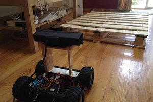
I spent the first three weeks designing and constructing the hull of the robot.
As for materials, I was given a sheet of 3mm Wooden board.
The not-so-nice final wiring of the robot, which, because of time constraints, consisted of stuffing the entire roadkill into the hull.
I thought an apt name for my robot was M1Rover. Because I’m planning to develop a versions of it in a sequence names like M2, M3, etc. It designed in a Kit, all you have to do is to assembly it with some screws.
Step 2: Components and Features
⦁ Up to three hours runtime!
⦁ Designed for the Arduino Uno, Mega and Nano.
⦁ 5V-9V DC Operating Voltage
⦁ A 3mm thick wooden chassis
⦁ 68mm diameter wheels L298N Dual H-Bridge Motor/Stepper
⦁ 9v batteries to power up the DC motors
⦁ 9v batteries to power up the Arduino
⦁ LED lights 7 for rear and front
⦁ HC-06 Bluetooth module
⦁ Arduino sensor shield v5.0
⦁ Ultrasonic transducer HC SR04
Step 3: The Motor Controller

H-Bridge's are typically used in controlling motors speed and direction, but can be used for other projects such as driving the brightness of certain lighting projects such as high powered LED arrays.
⦁ Make sure you have all of your grounds tied together; Arduino, Power source, and the Motor controller.
⦁ The PWM Pins are unnecessary if you do not want to control PWM features.
Step 4: Assembling Chassis

Chassis has been cut using laser cutter in a few parts, and as I mentioned before the model was created in a kit easy to assembly, so all you have to do is to follow the instructions below.
Considering the design was also important and when it comes to RC cars it should contains of front and rear lights. At the front of M1-Robot I put 4 white LEDs each one is connected to 220 ohm resistor, and in the rear I put 2 red LEDs with 220 ohm resistor for each. These LEDs can be controlled by the same application
Step 5: Circuits

Circuit was little bit tricky because when you decided to control many electronic parts at the same time you should take care about the sequence of each part.

⦁ Arduino Sensor Shield 5.0
⦁ Arduino Uno R3 L298N Dual H-Bridge Motor/Stepper
⦁ 9v battery to power up the DC motors
⦁ LED lights 7 (2 rear) and (4 front)
⦁ HC-06 Bluetooth module
⦁ Ultrasonic transducer HC SR04
⦁ Servo motor 9g
⦁ Active Buzzer
⦁ 4 DC motors with wheels
Step 6: Software

I considered amount of things while writing the code of M1-Robot, and with GUI software you are able to get more information about robot status.
Actually the codes are separated in two parts:
⦁ Arduino Code
The Arduino code is compatible with any kind of controllers because all the electronic parts are programmed to work through serial port orders, so you may use Bluetooth module sender/receiver, PC, Cell phone.
⦁ C# windows application (screenshot attached)
Step 7: PACKAGES
STARTER

This M1rover package entails basic components while the top plate allows for easy mounting of any sensing, manipulation or computer hardware. Simply attach sensors to the onboard and Rover power supplies to get started.
EXPLORER

The Explorer package enables basic indoor and outdoor autonomous functionality, and instate of IP camera I used a mobile phone cam connected to the internet via IP address.
MAPPING
The Explorer package enables basic GPS tracking of course while the vehicle is outdoor, it’s very cool when you watching the coordinates paths in the real-time.
MANIPULATION

Interacting with the world with a robot arm and a 2 finger 50mm Gripper
Important Tip:
Not all servos have a full 180 degrees of rotation....
Read more »


 Shawn Chen
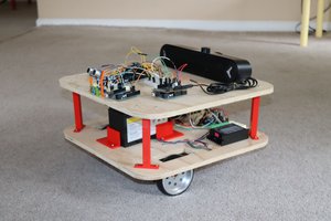
 Mike Rigsby
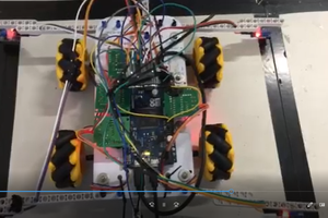
 Miguel Wisintainer
 mircemk
Fantastic project Ahmed! I've ordered the parts to build one. Are the design files available for the body?