 Jack Flynn
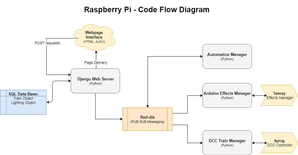
The project details will expand as we progress, however, for now these diagrams outlay the main project design as it currently stands;


Custom coffee table with a DCC train track, automation, LEDs and a web interface
Already have an account? Log in.
To make the experience fit your profile, pick a username and tell us what interests you.
The project details will expand as we progress, however, for now these diagrams outlay the main project design as it currently stands;
We had our first real life test run with my son in the drivers cab. The trains worked excellently, the interface is smooth and responsive and most importantly; it was fun! The smile on my sons face meant that all the work thus far was worth it, and oh boy has it been a lot of work. The latest changes over the weekends have been code based and a little bit of hardware. Reliability and ease of use have been at the forefront and there was a key issue holding the trains back that we solved.
The DCC protocol for getting the trains to move is a serial data packet that is sent through the rails of the train track to each train. These packets are decoded and if the address of the packet matches the address of the train then the train reacts accordingly; whether it's speed up, down, lights on, off or any other functionality that's available. This works really nicely and data transfer is great for handling multiple trains on the same rail line.
Where it breaks down is when the train and the track don't meet together perfectly. A single drop in connection and the train suddenly stops, dead in the water. The system then needs to send a new packet to get the train running again. Even if the drop in connection is a tiny fraction of a second, the train returns to its default state as it experiences a power cycle. For us, this meant we could get the train rolling with a command via the interface but then the train we get to a dirty point on the track and stop moving. Clicking some more on the interface would get it going again but obviously this wasn't what we intended.
In order to solve this issue I reworked the DCC interfacing scripts to periodically refresh the trains by sending out speed and light state packets every 100ms. The script pulls latest data from the database for each train and sends out the data accordingly once the timer fires. As of today, this has worked flawlessly and we're getting a really fast response from the trains via the interface.
Once we had the trains running reliably the next focus was to make the lighting more interactive. Every light has a database entry which includes state, brightness, address and a title. The Django server pulls this data and displays a list of buttons and sliders accordingly which allows us complete control of every single light on the table.
Single light control is cool but a tad tedious. No one wants to have to turn off every single street light individually when what we're trying to achieve is all on or all off. In order to simplify the lighting control down I decided to make an additional object in the database which I refer to as "Light Groups". These light groups can be configured with their own state and brightness and hold a list of all of the individual lights in the group. By toggling the group the Pi sends out a state and brightness command for every light in the group to the Teensy and it adjusts the individual LEDs accordingly.
The key benefit of this is that the light groups are defined at the database level which means no arduino code was required to make it work. The groupings are also managed via the Django Admin page which means they can be set up while the table is running super easy. Even my Dad can manage it :p.
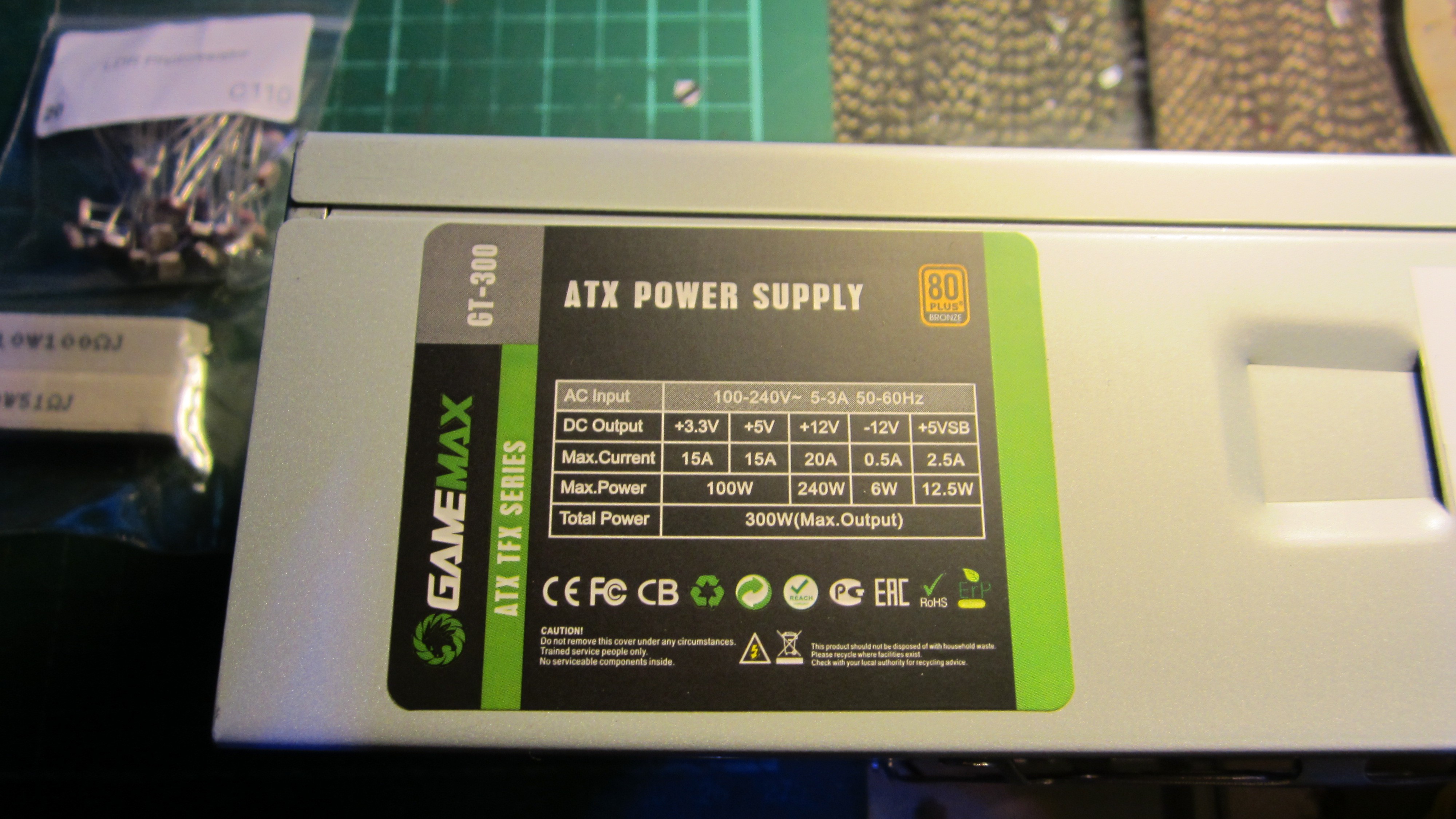
So we have a whole host of LEDs on the table. One of pieces we bought off the shelf is the N-Gauge cars with front and rear LEDs for headlights. The unexpected side of these off the shelf models is that the LEDs are in series rather than parallel. This means our standard method of 5v PWM wouldn't work for lighting as 4 LEDs in series creates a roughly 9V drop across the LEDs; tested that the light with a 9v battery. Thankfully through the use of a PC power supply, we have a 12V line available for use; that just leaves interfacing.
In order to prevent creating a whole new management method for the Car LEDs, I decided to...
Read more »
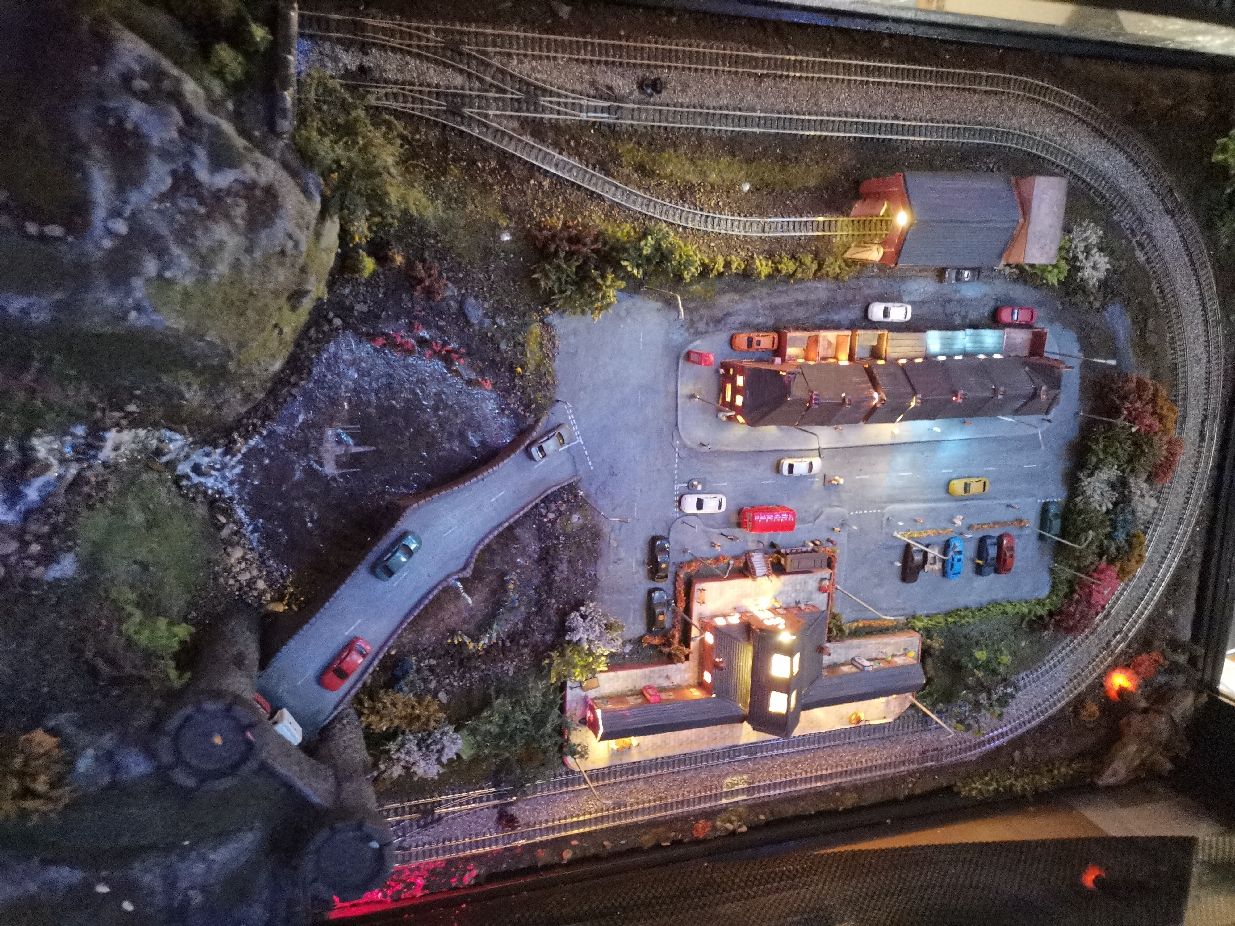
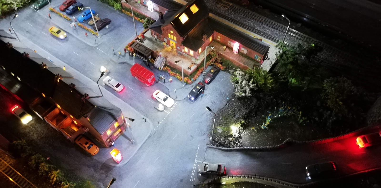
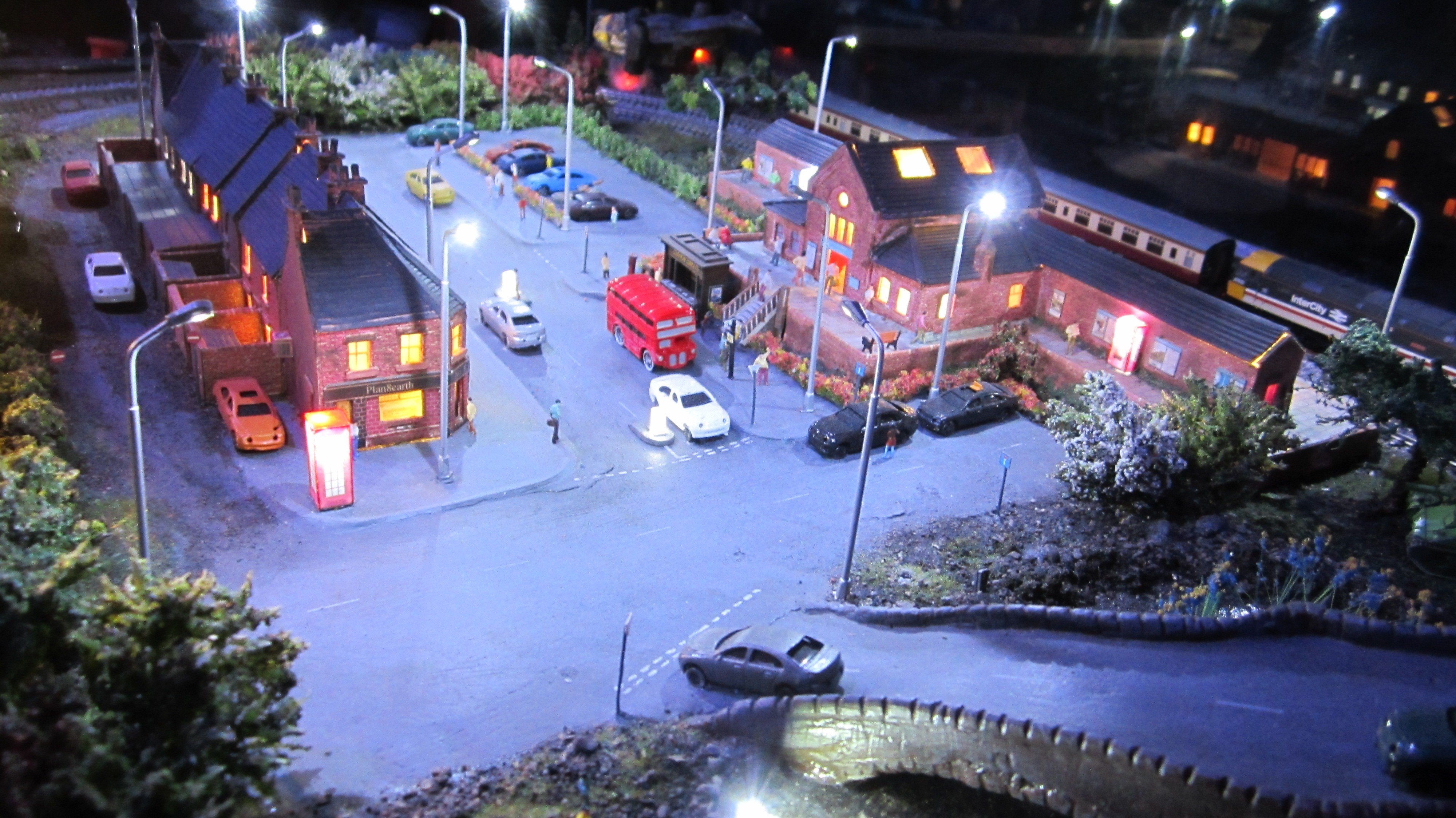
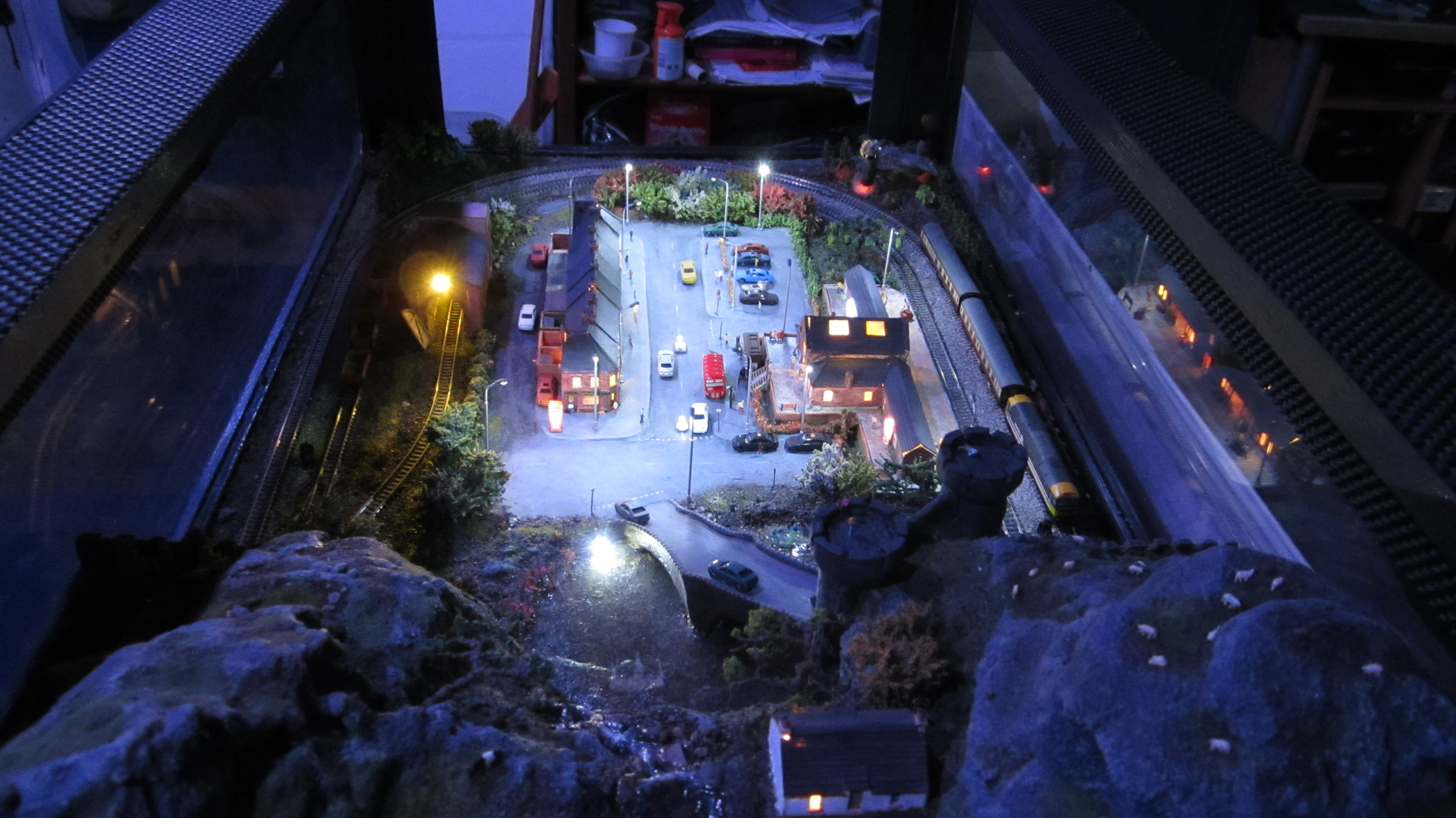
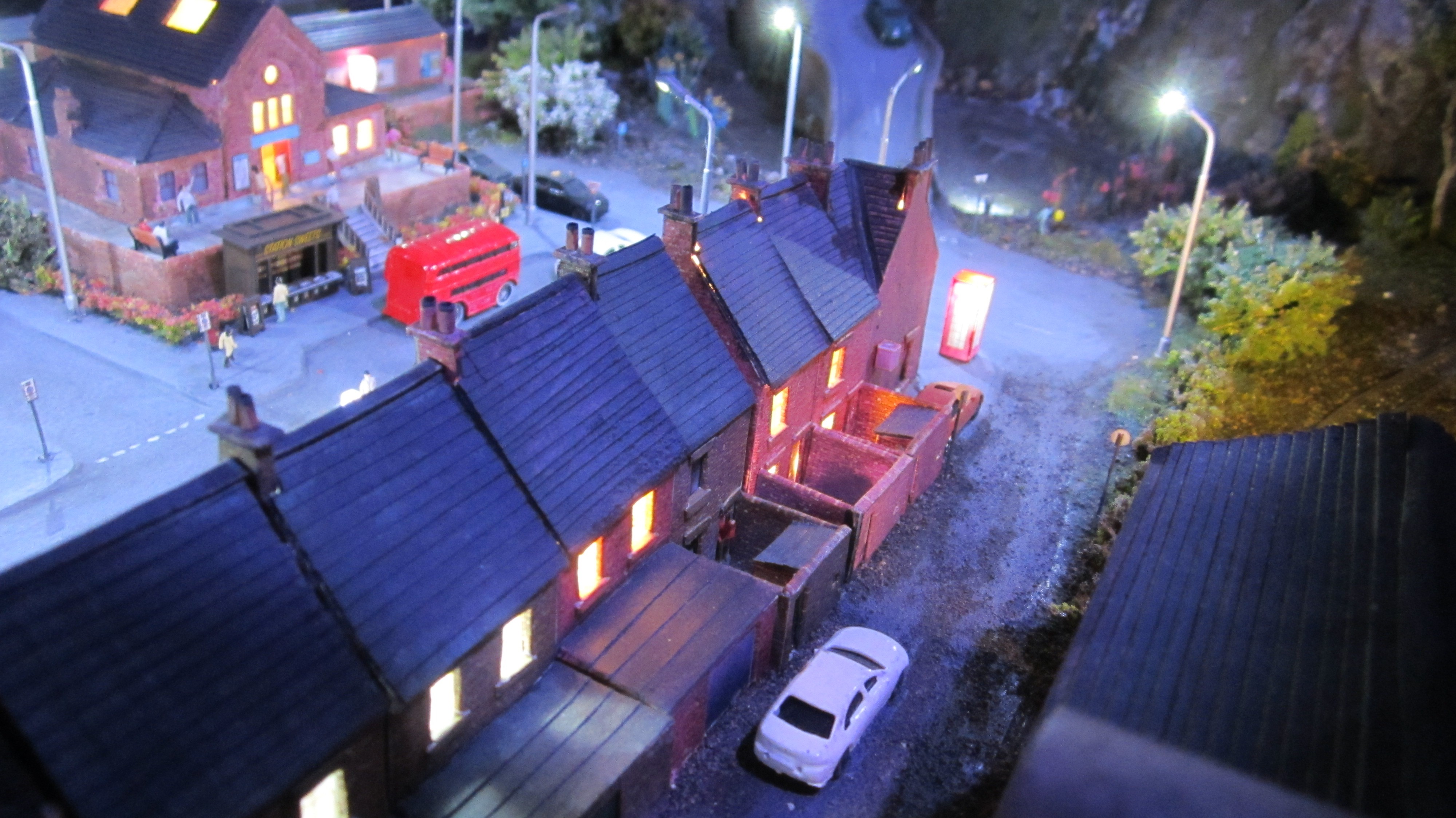
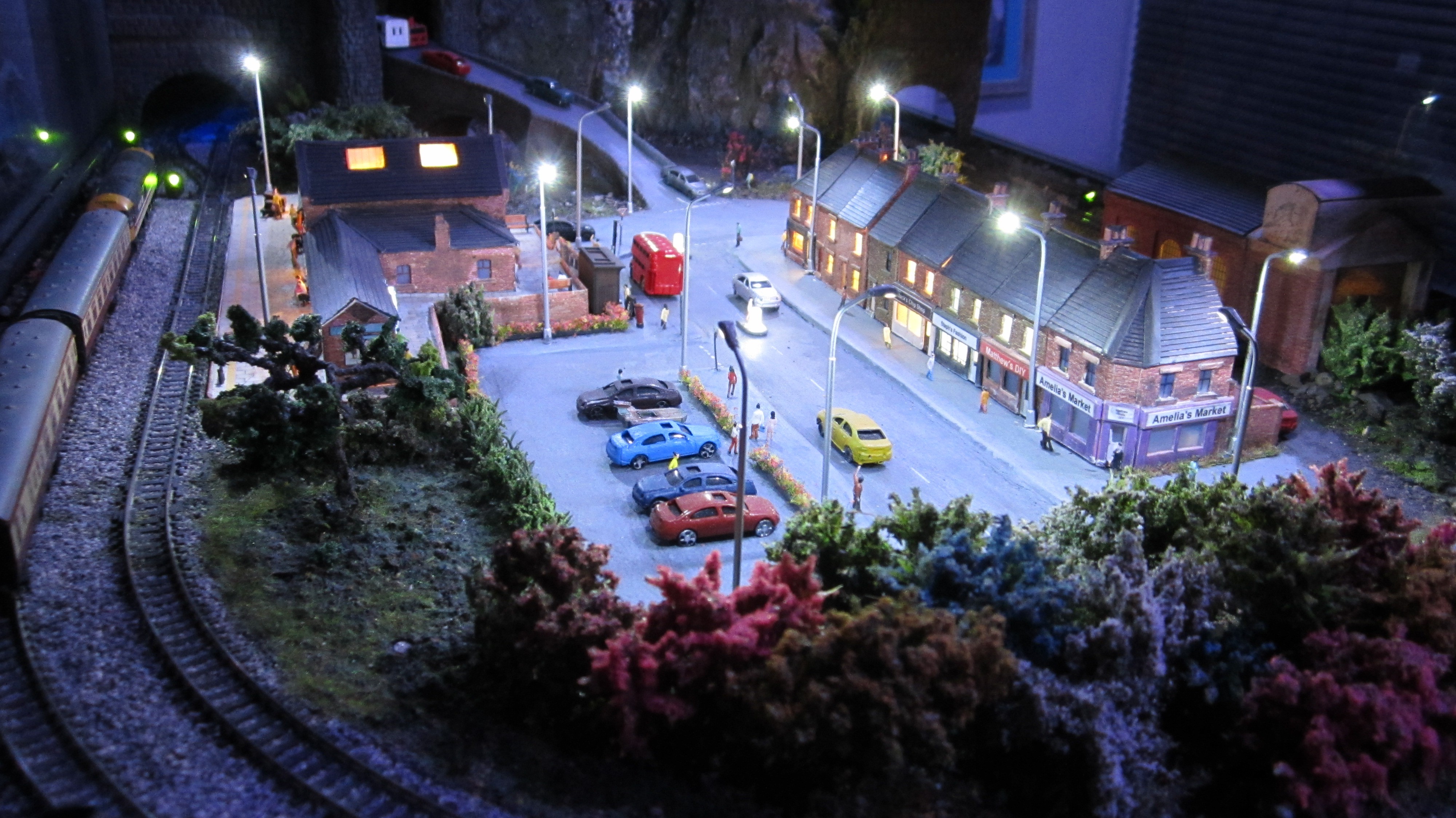
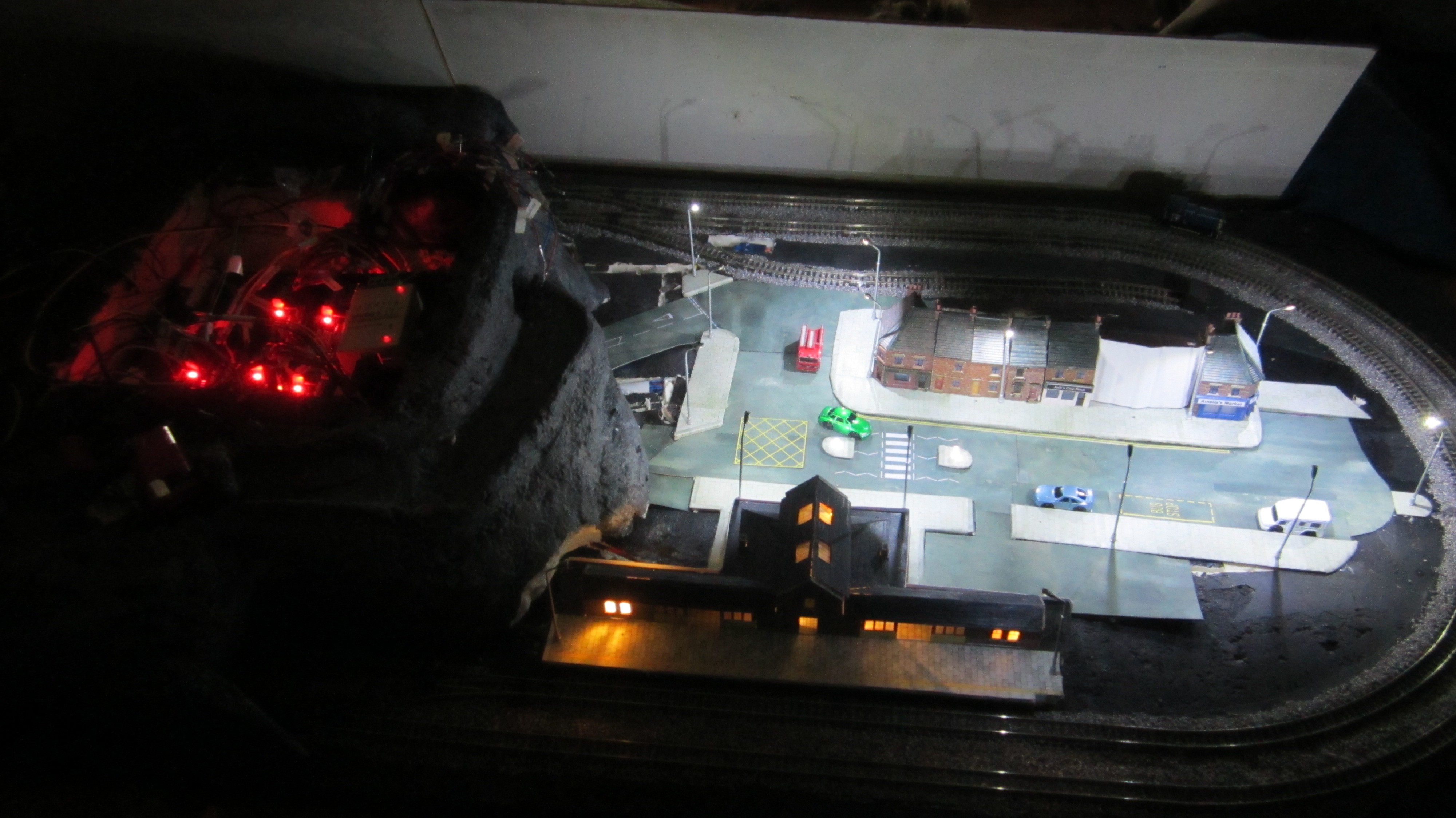
Oh boy, it's been a while! There has been so much work put into the table, I simply don't know where to begin, but this weekend we tried our second ever power test and although there were some wiring teething issues it was awesome! The video below shows how far we've come and at night time the table looks fantastic. Each LED is individually controllable which can be seen in the second video as we're cycling through them with an on/off test code.
So many things to cover but essentially we've followed the plan as intended. The wiring is working, the LEDs are lighting and the Pi and Teensy are talking so we have control via the web interface. I completed a pretty big overhaul of the code once I realised just how difficult it is to manage individual states of components like this. Originally the Teensy had defined addresses for each LED and was going to manage those locally but the power of the Pi running Django with a SQL database made it much clearer that the better way to do it was to use the Teensy as a physical interface and manage the states via the database. This means I can offload the LED automation from hard coded Teensy control, to a more flexible database system. So in the future I'll be able to make changes like adding groupings of LEDs (say Houses! for example) and with each LED added to the "Houses" group I can easily control the state of multiple LEDs with a group that can be reconfigured at any time without having to upload code!
Further work was also done to get the Pi automatically launching the Django server as well as my custom scripts for interfacing to the Teensy and the Dcc Controller.
More of my weekend was taking up improving the code than actually working on the electronics. So we've got a fair bit more low level board work to do;
We'll get there, big demo time will be Christmas!
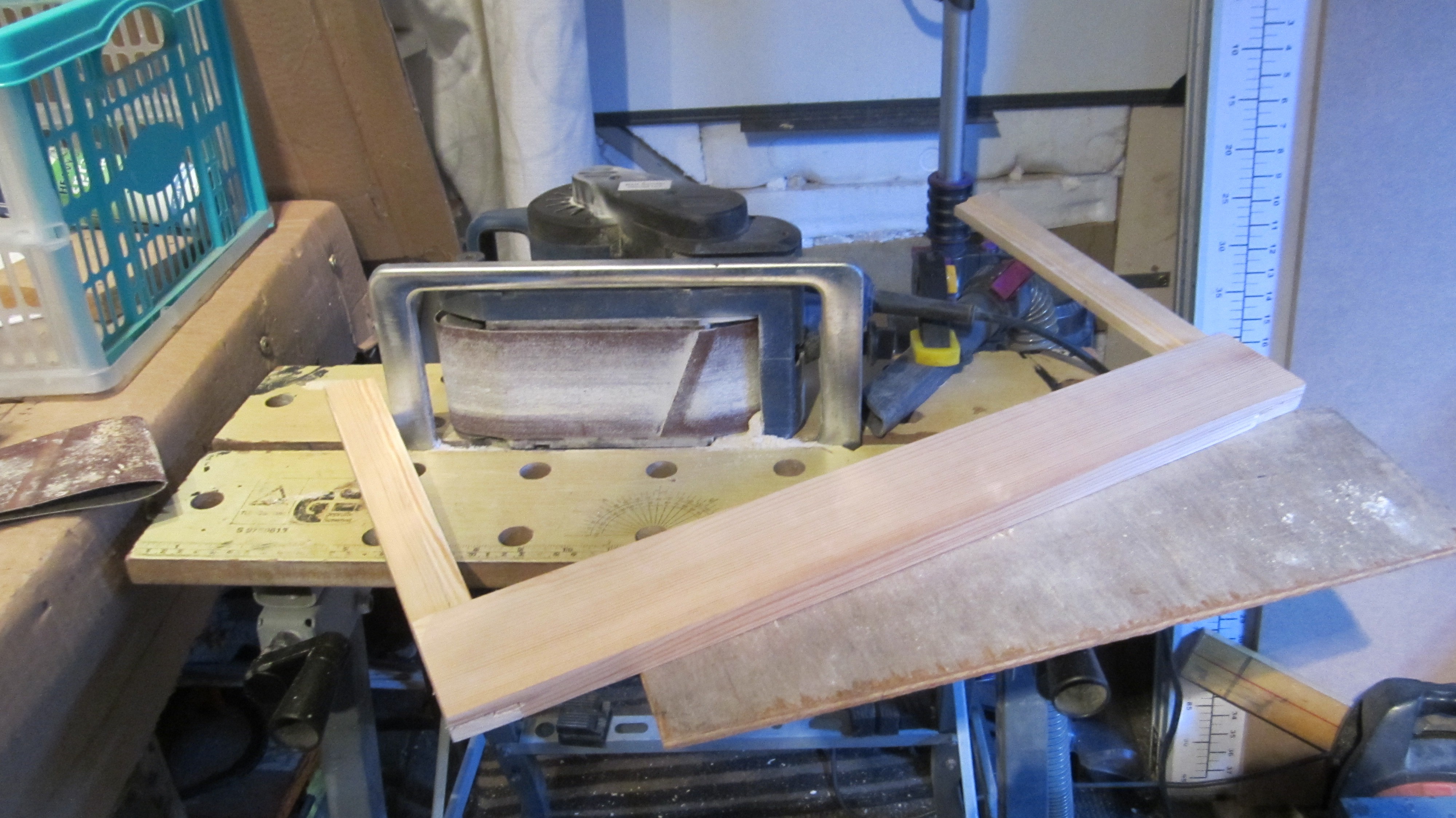
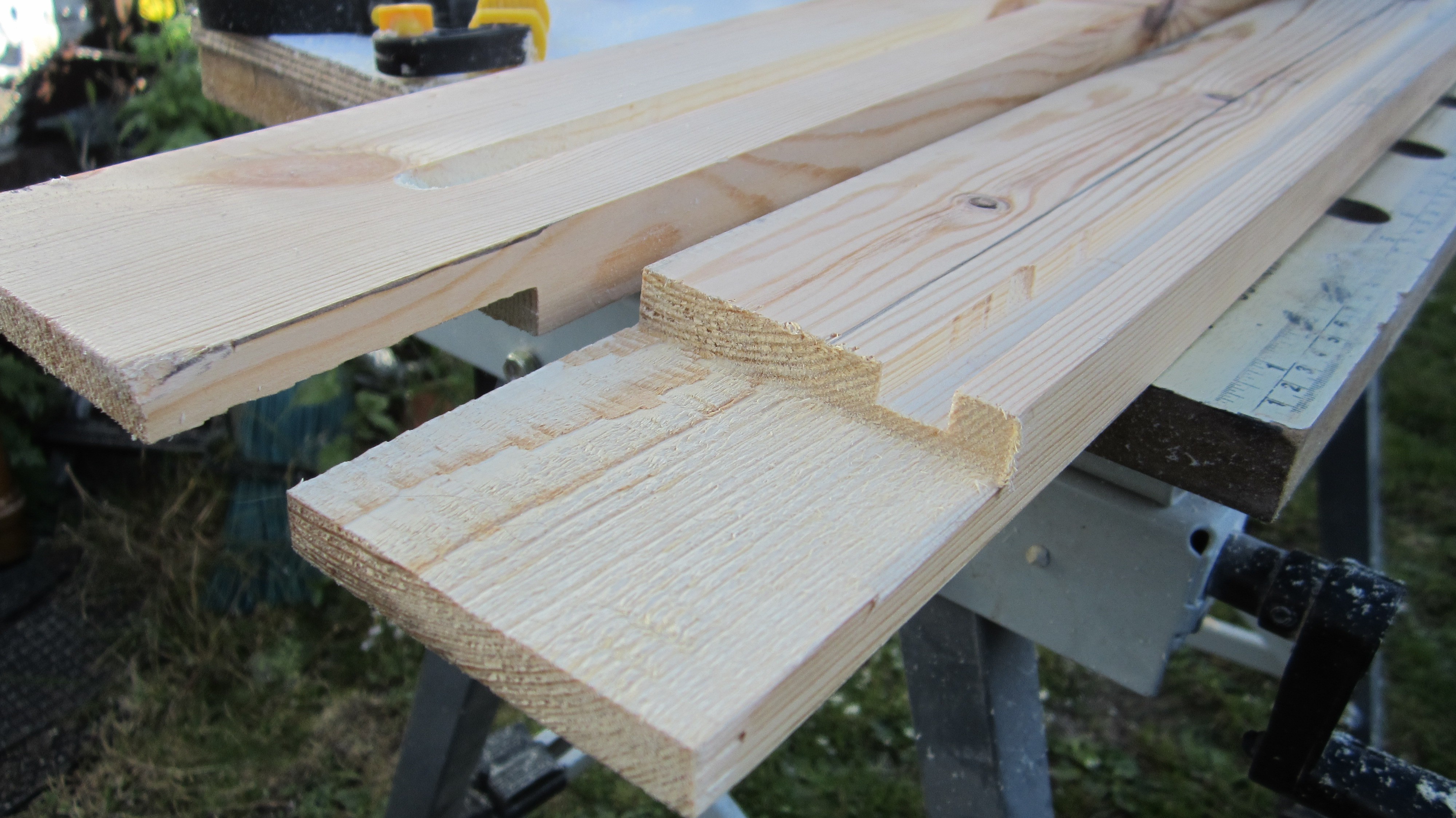
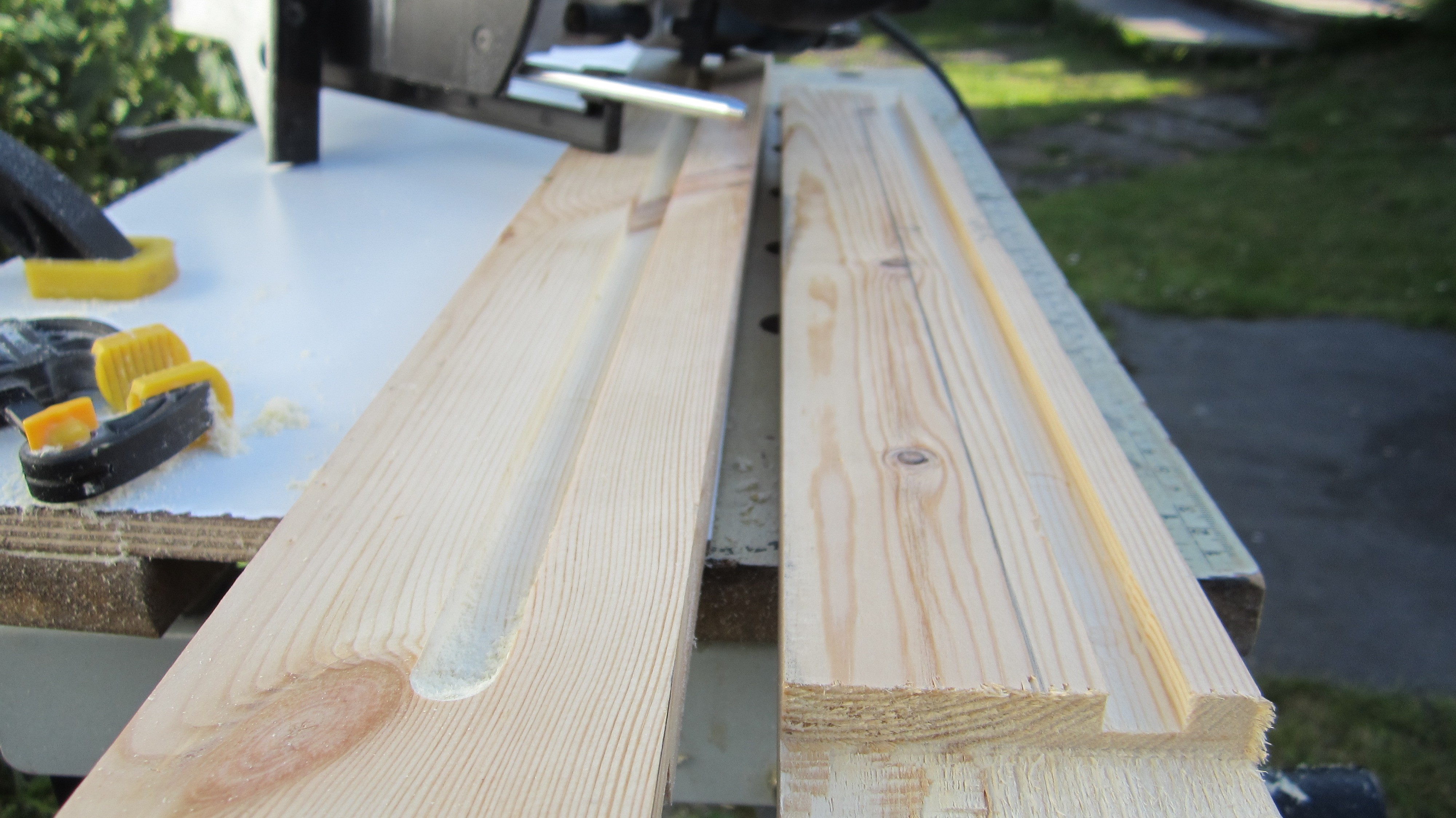
Woodworking should be in my blood, my Dad was an "old school" joiner to trade, I have inherited a lot of tools and have been using them a lot in this project, learning to use them has been a combination of childhood memories, from all those summer school holiday's with Dad as Day Care was not a thing in them days, and Googling best practices. Master Carpenter I am most definitely not, but an enthusiastic amateur with a garage full of old tools, a hackers spirit and a very limited budget. I like them odds!
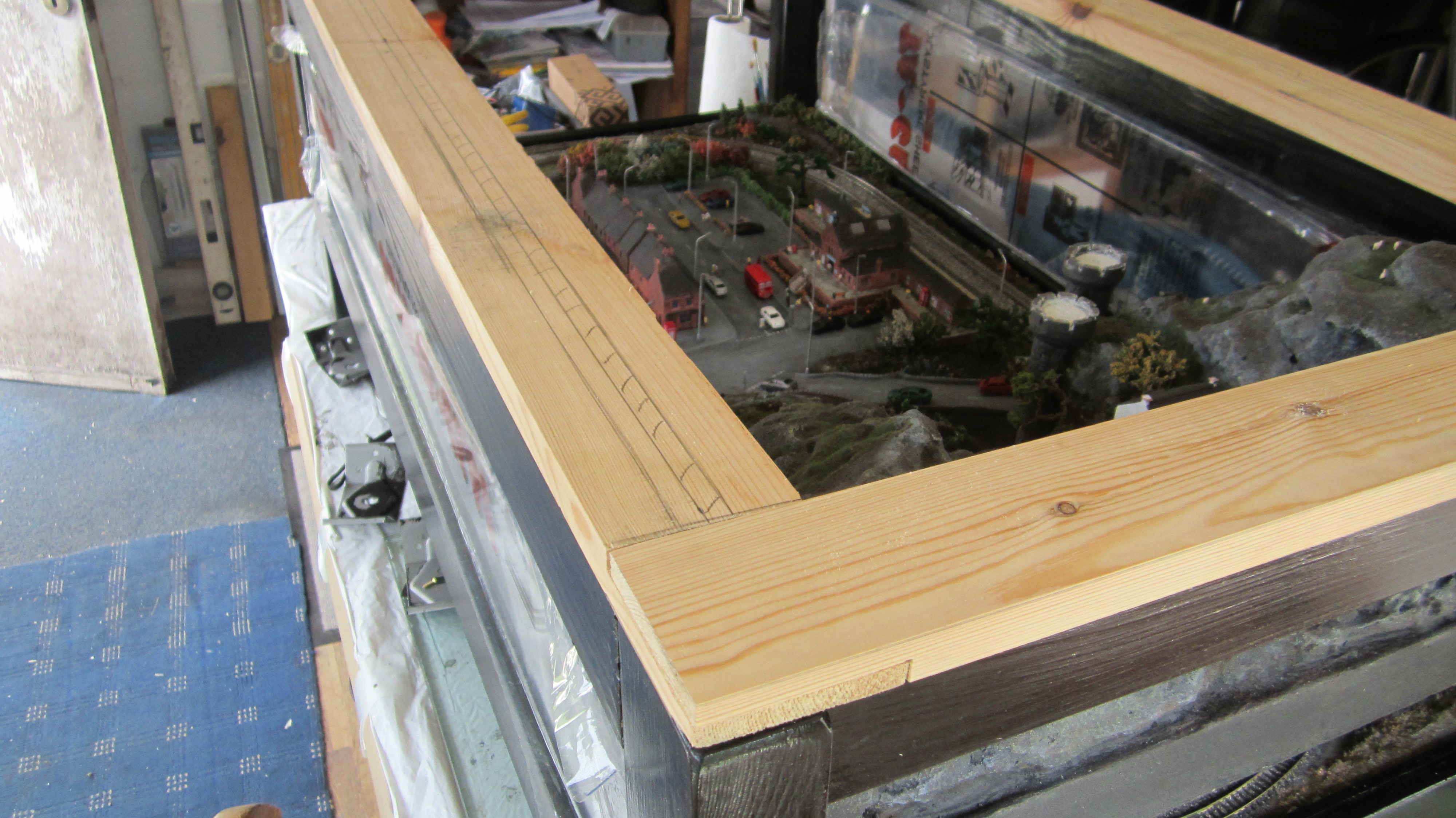
Having the main Diorama part of the project 95% completed the focus for me is the Coffee Table Woodworking. Jack is working on the electronics and the plan is to get a day or two together to complete the electronics installation.
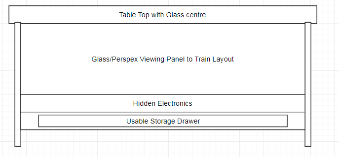
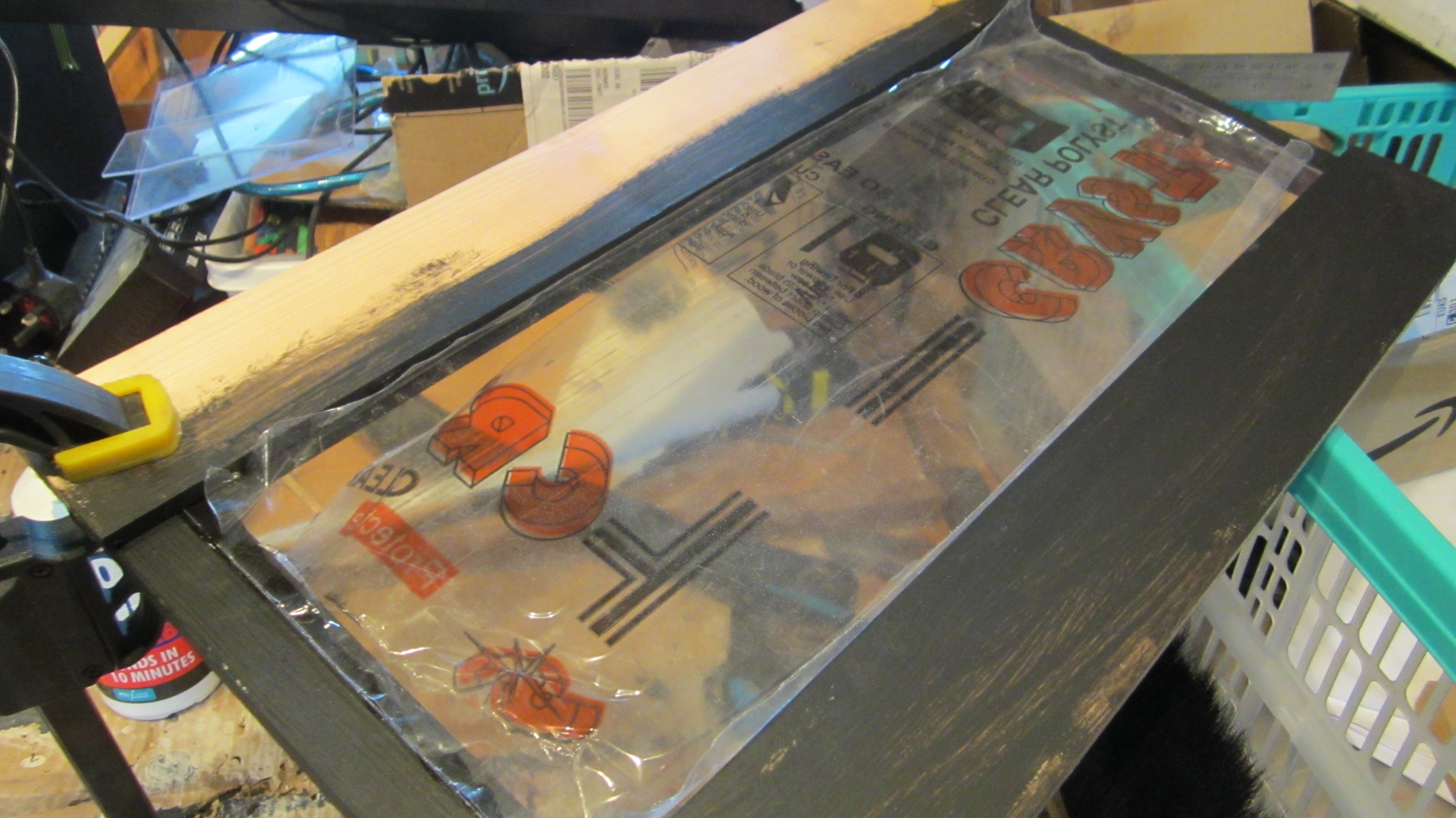
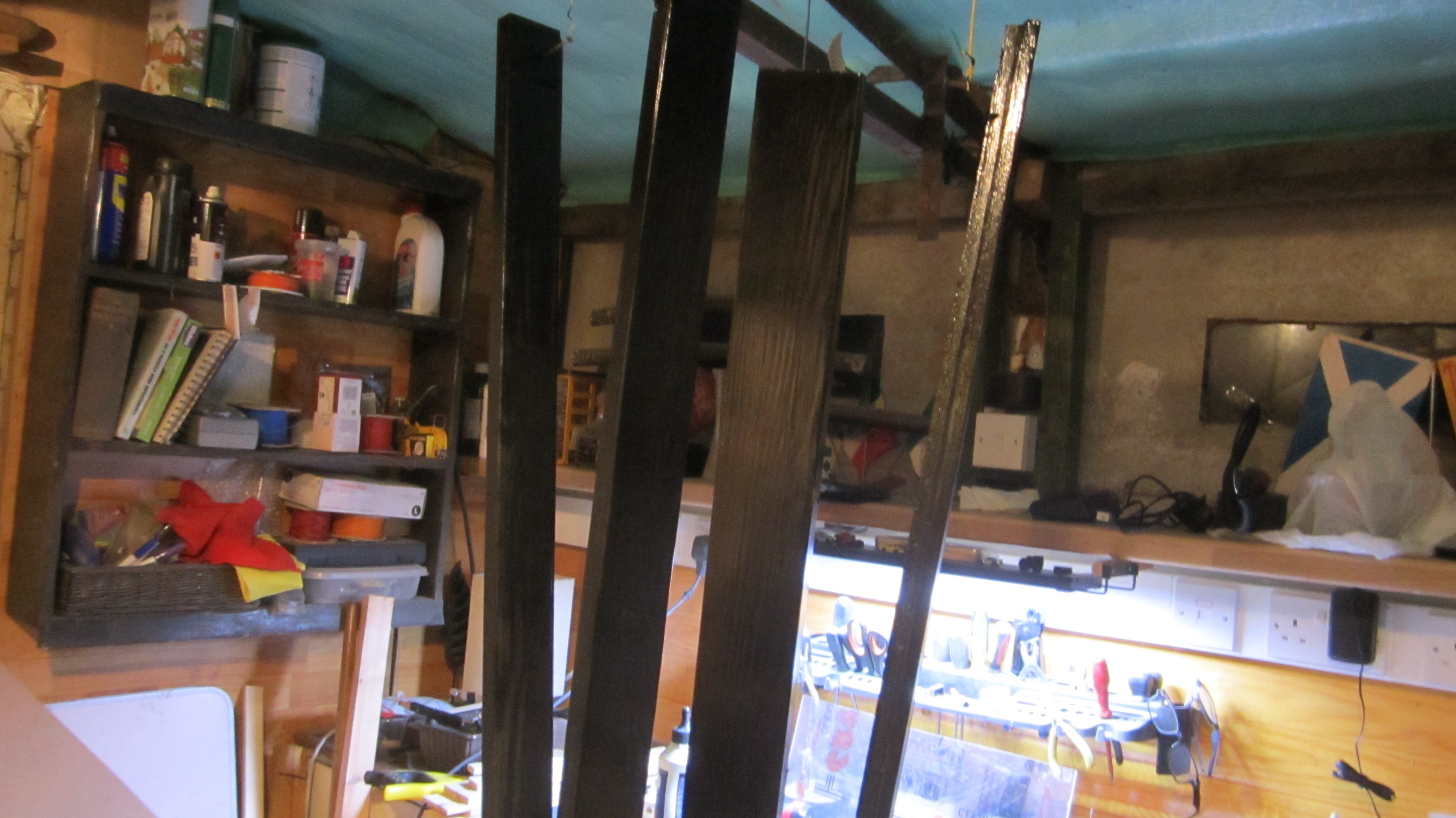
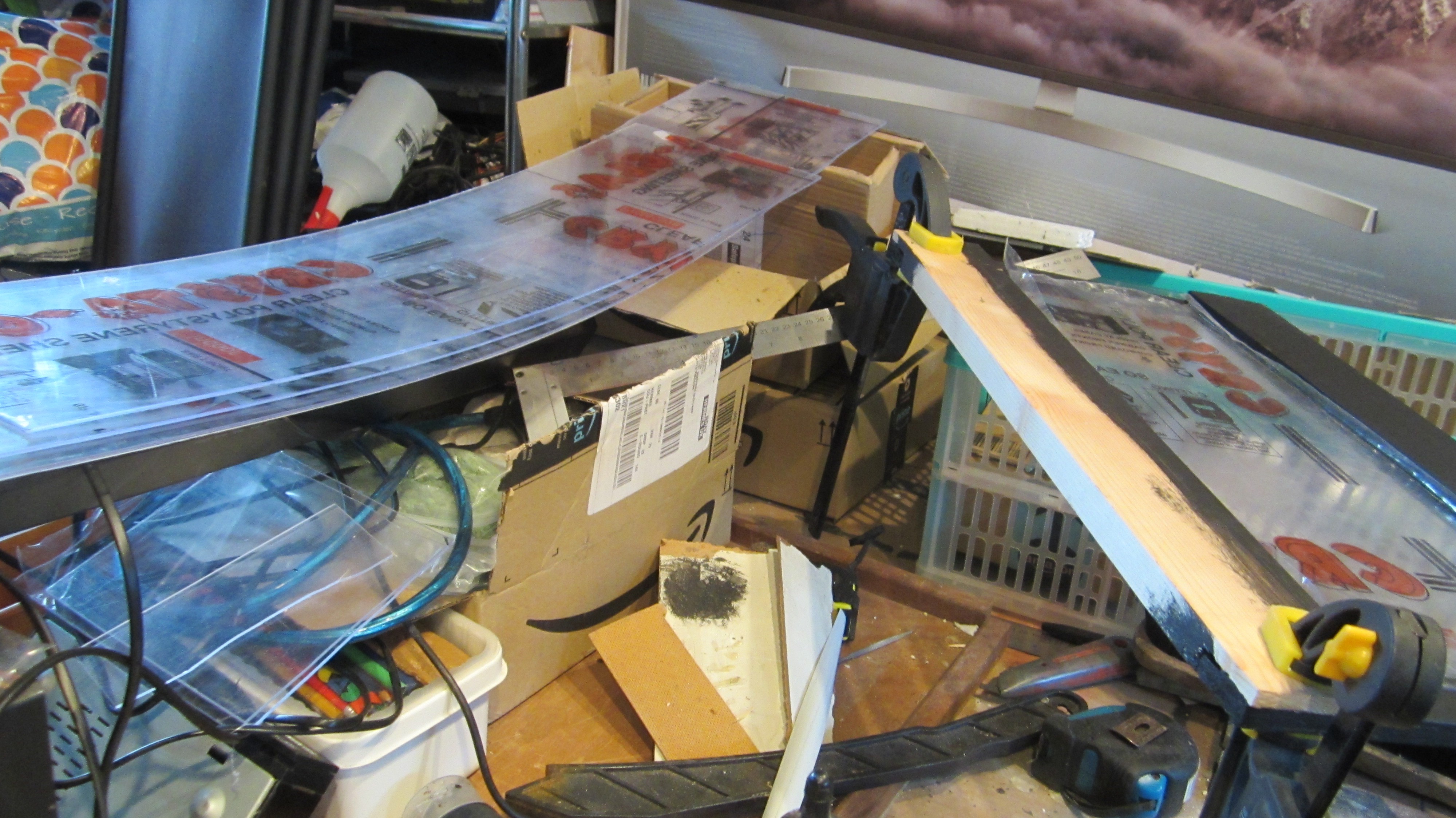
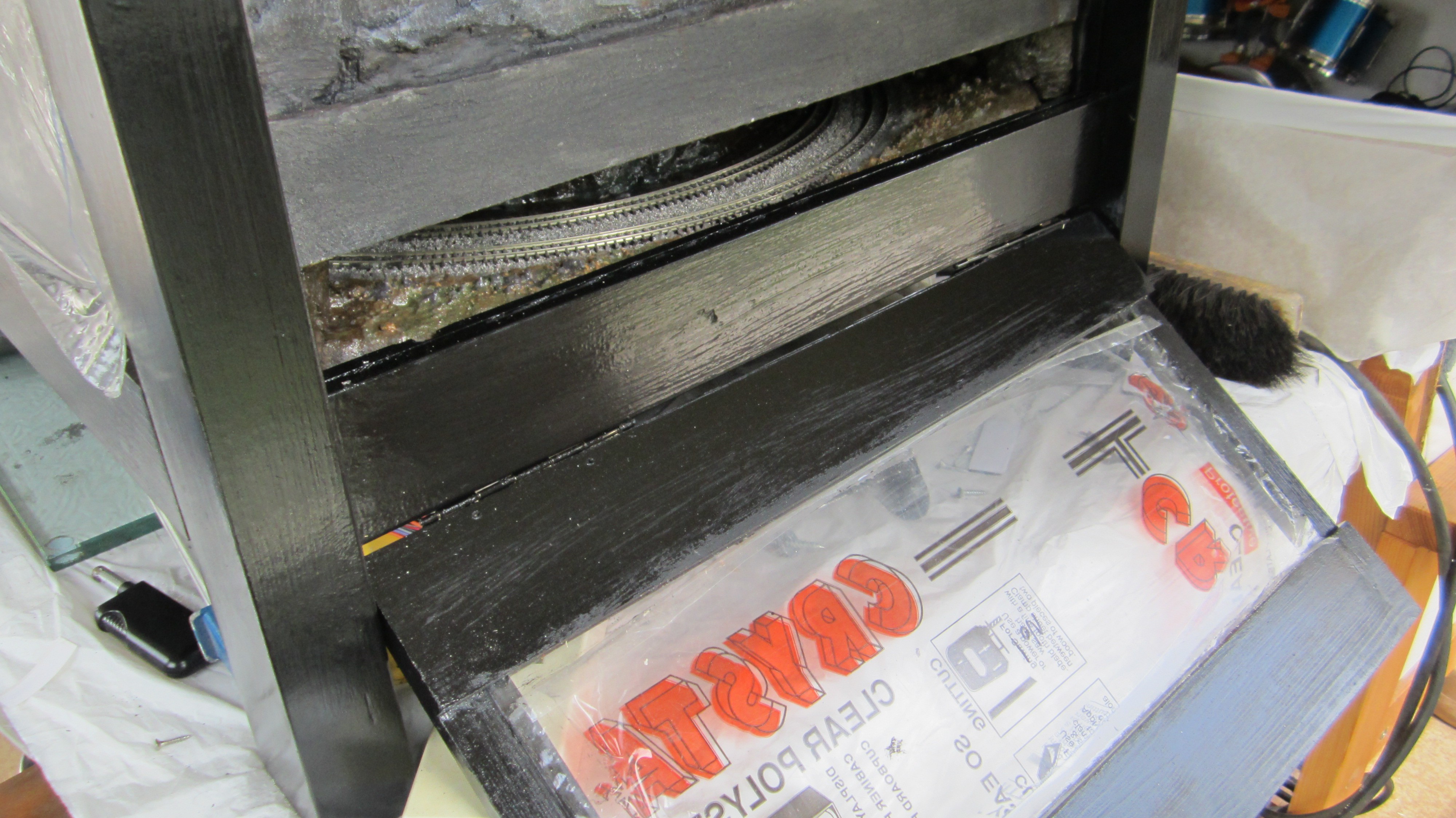
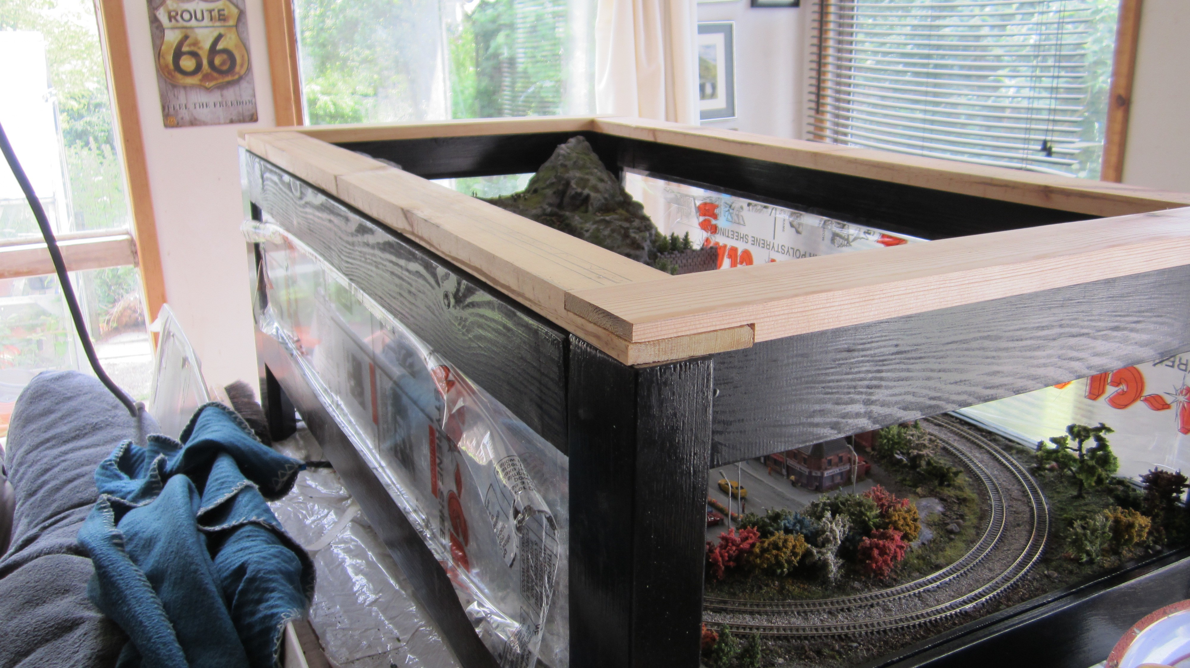
The acrylic sides and rails needed fitted, the top rails that will have a RGB LED strip lighting on the underside inner, the top of this rail will support the hinge and gas strut for the hinged top.
We realised access to the track in the tunnel for fixing derailments and for track cleaning was going to be required, a hinged access hatch was needed for each end, the opening top will give access to the rest of the layout.
The Top will have the tempered glass inlaid flush to the top surface in the centre of the top.
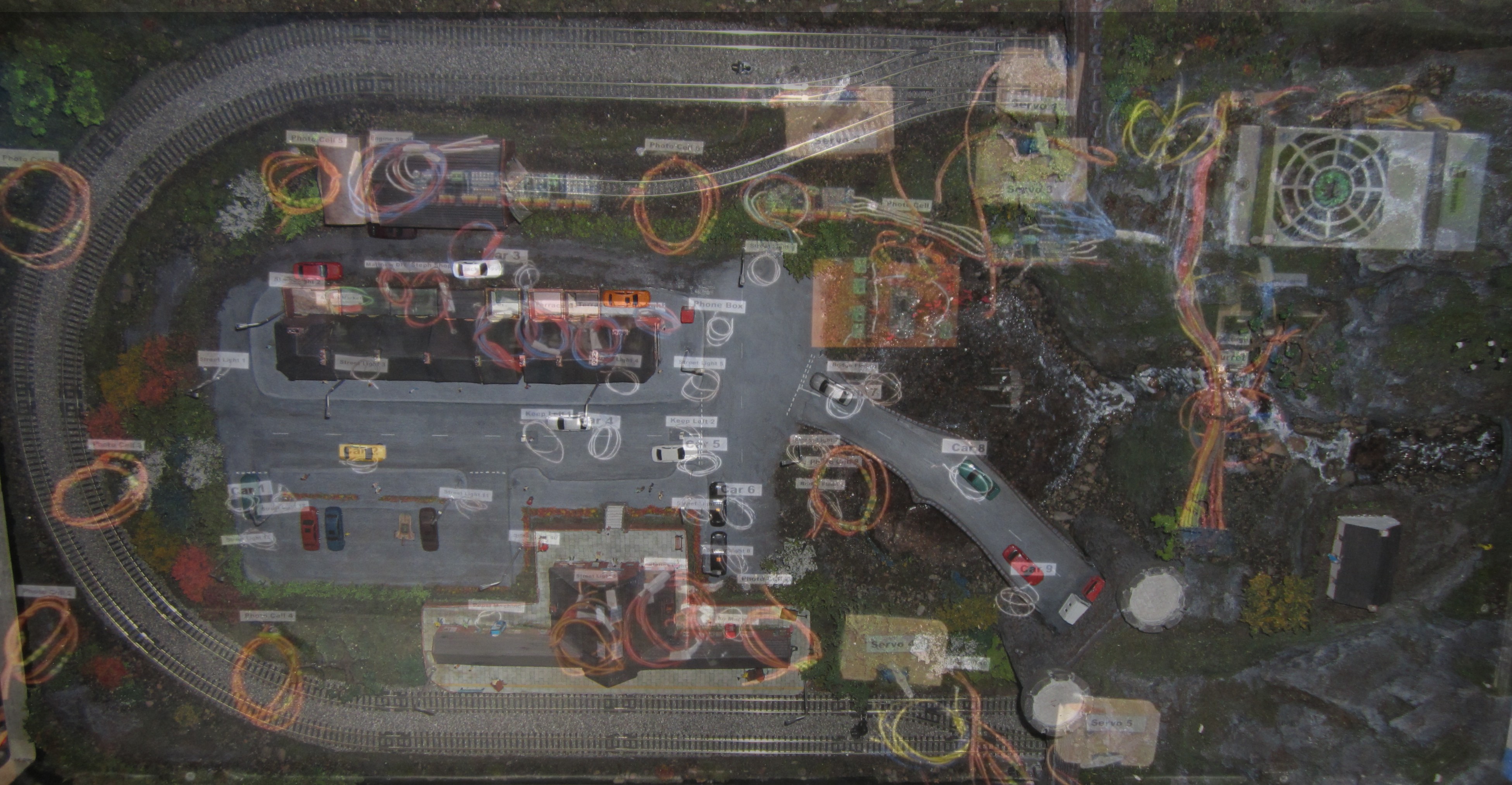
I think about that phrase a lot when I'm putting together circuits. Sometimes it works, sometimes I get carried away with the fun of building. However, (un)fortunately, I'm not onsite with the table so the best I can do is plan ahead and with that in mind I put together the rats nest below as attempt to plan out all of the inter-connectivity that we'll have on the table.
It was modelled in Fritzing *GASP!*. I know, but despite fritzings uselessness for pcbs and schematics, it does print a pretty picture and it had 90% of the device images that matched what we're actually doing on the table.
Hopefully design and reality can meet somewhere in the middle;
Finally got to do this log, apologies for the gap. a lot has happened, we have learned so much and loved every minute of it. This is a brief summary of events of the past 5 months (that long... really!) I have to say that it has been well worth it, a rethink and redesign has really paid off, but first a recap.
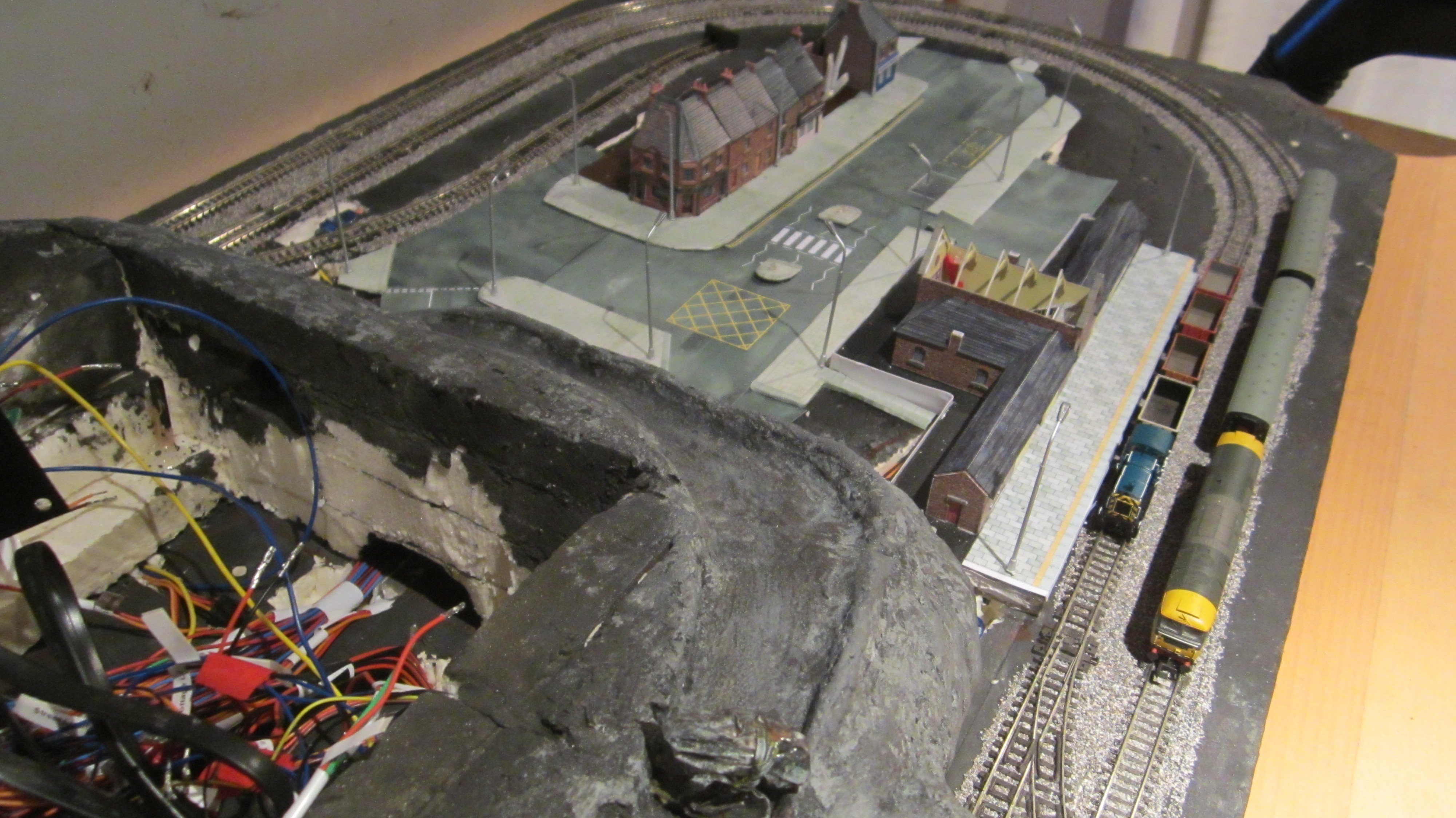
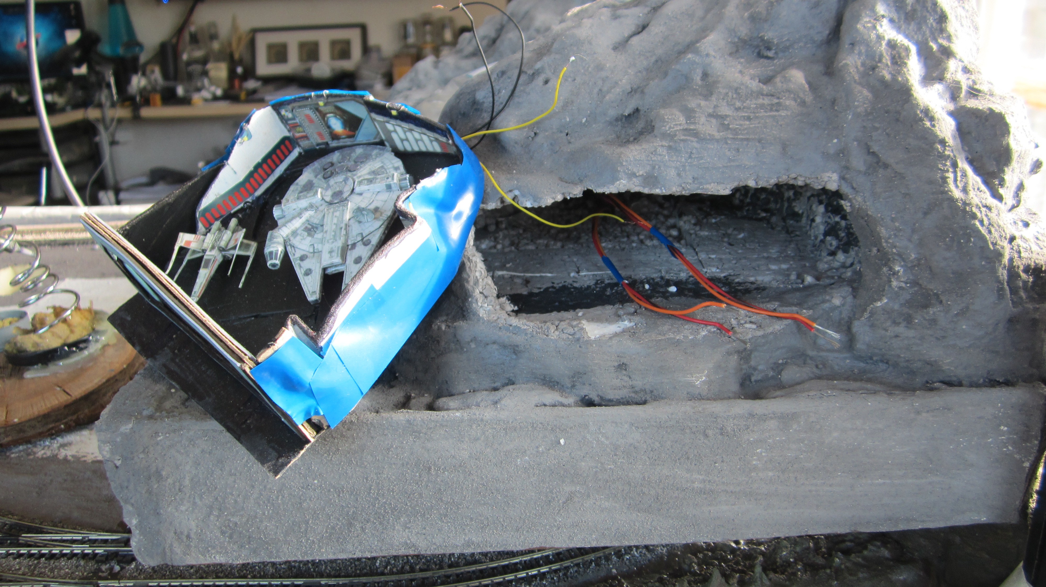
The wiring was embedded in the foam board, this would prove to be the wrong approach, wiring was run back to the control boards that we test fitted inside the hill, this also proved to be the wrong move but ignorance is bliss and we pushed on to get to a point of testing functionality.
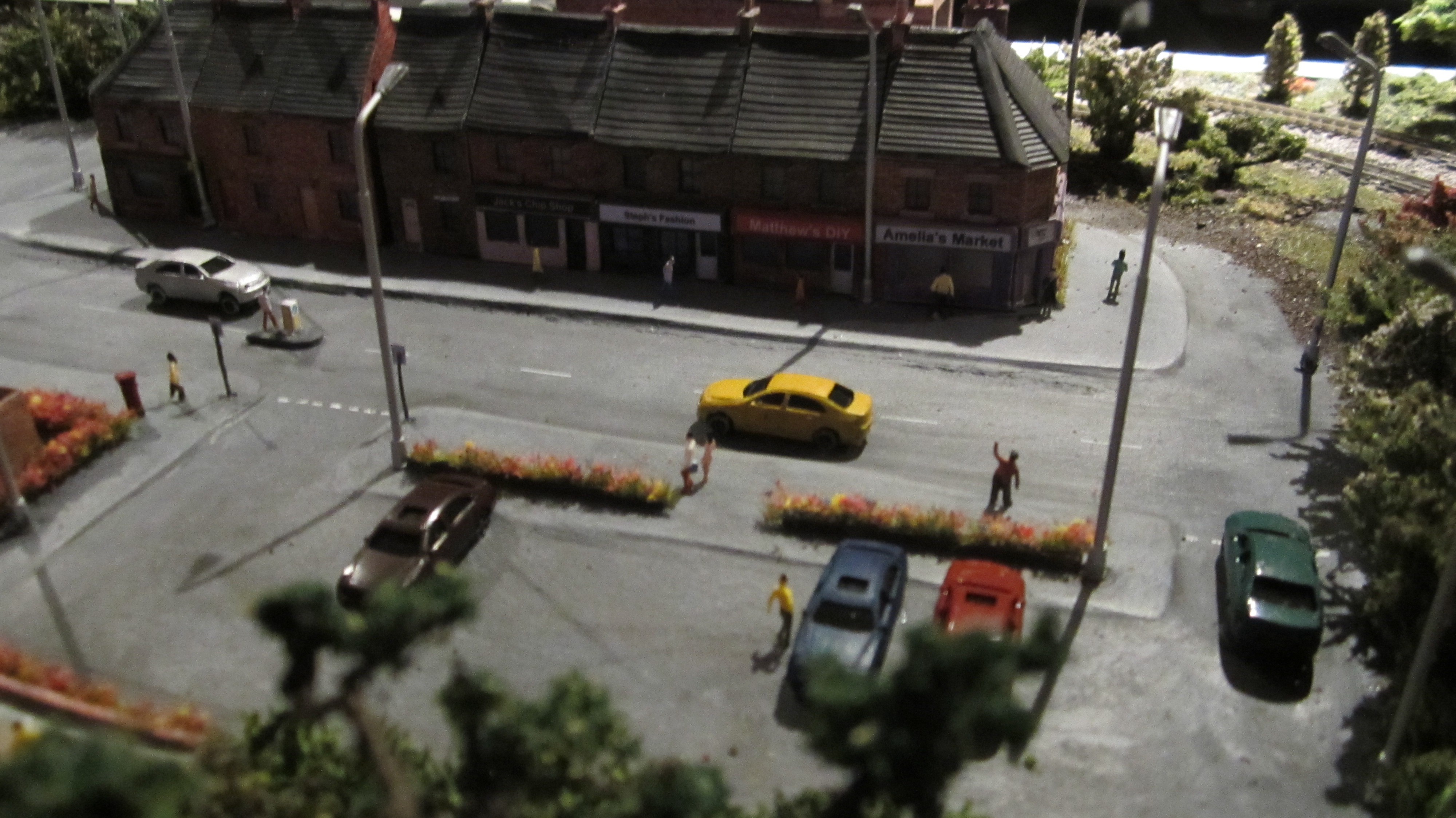
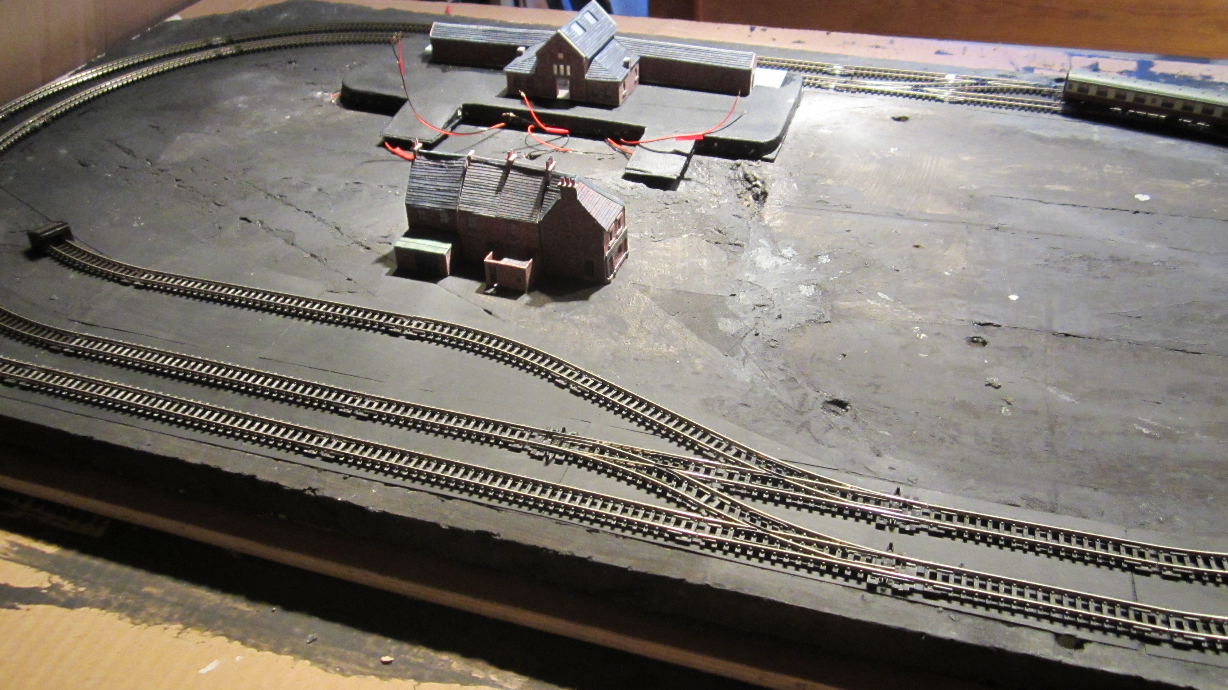
I downloaded a set of n-scale roads and printed them out, I then built up the road layout hiding the embedded wiring below the roads, I added the building that were complete and we were able to test run for Xmas day.
We learned a great deal from our test run, the proof of concept was really successful, the lighting looked awesome and the project "cool" potential was huge. The main lessons learned were we could not cut corners, we need to do this justice, we decided to remove any time restraints we had given ourselves and having mercilessly explored layout modelling on YouTube, we developed a new plan.
Lessons learned so far
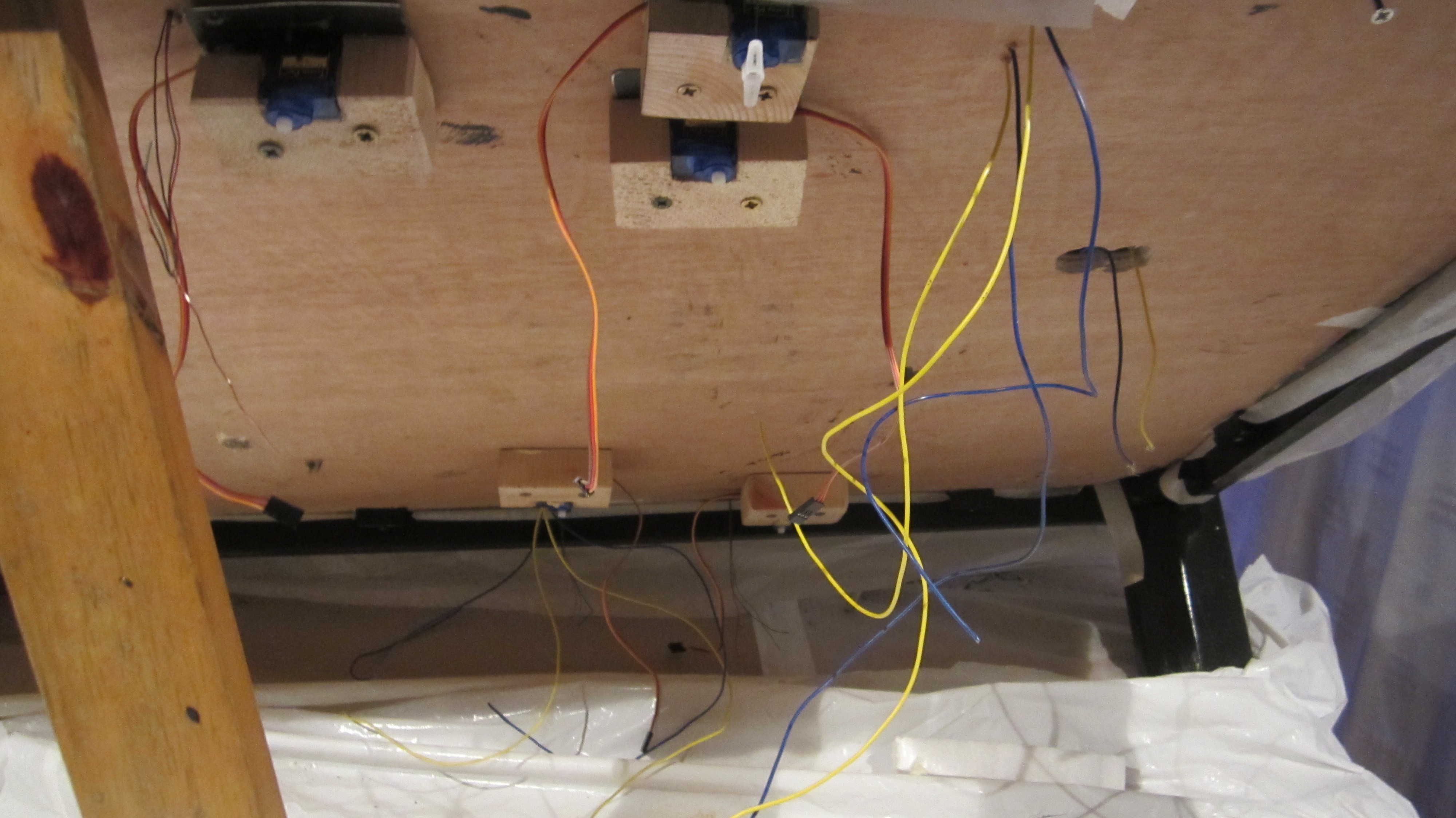
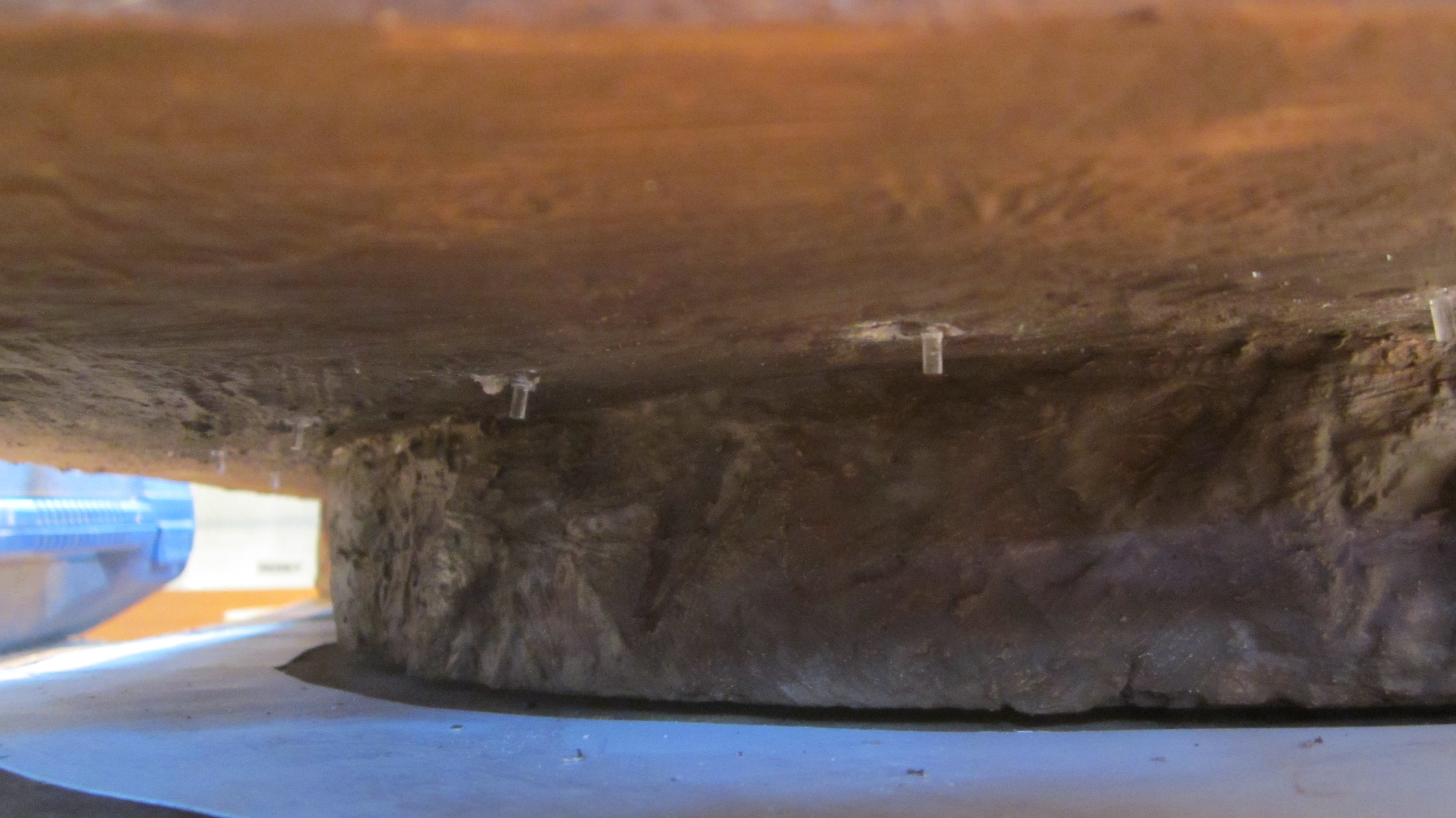
1. Embedding wiring is not advisable, the conventional way is to drop the wires straight through the board to underneath the layout, allowing easy maintenance or fault finding.
2. Like point 1 the control boards need to be fitted on the underside of the layout for the same reasons, the original idea was to have a drawer in the bottom of the table and we attempted to contain the wiring and controllers in the foam core and inside hidden the hill, this proved impractical and woefully inadequate as the electronics list expanded.
3. We attempted to use an old kitchen table to make the coffee table, it quickly became apparent that we needed to build our own frame, the cost to adapt the kitchen table was comparable with buying the wood, we could then design and build exactly what we needed.
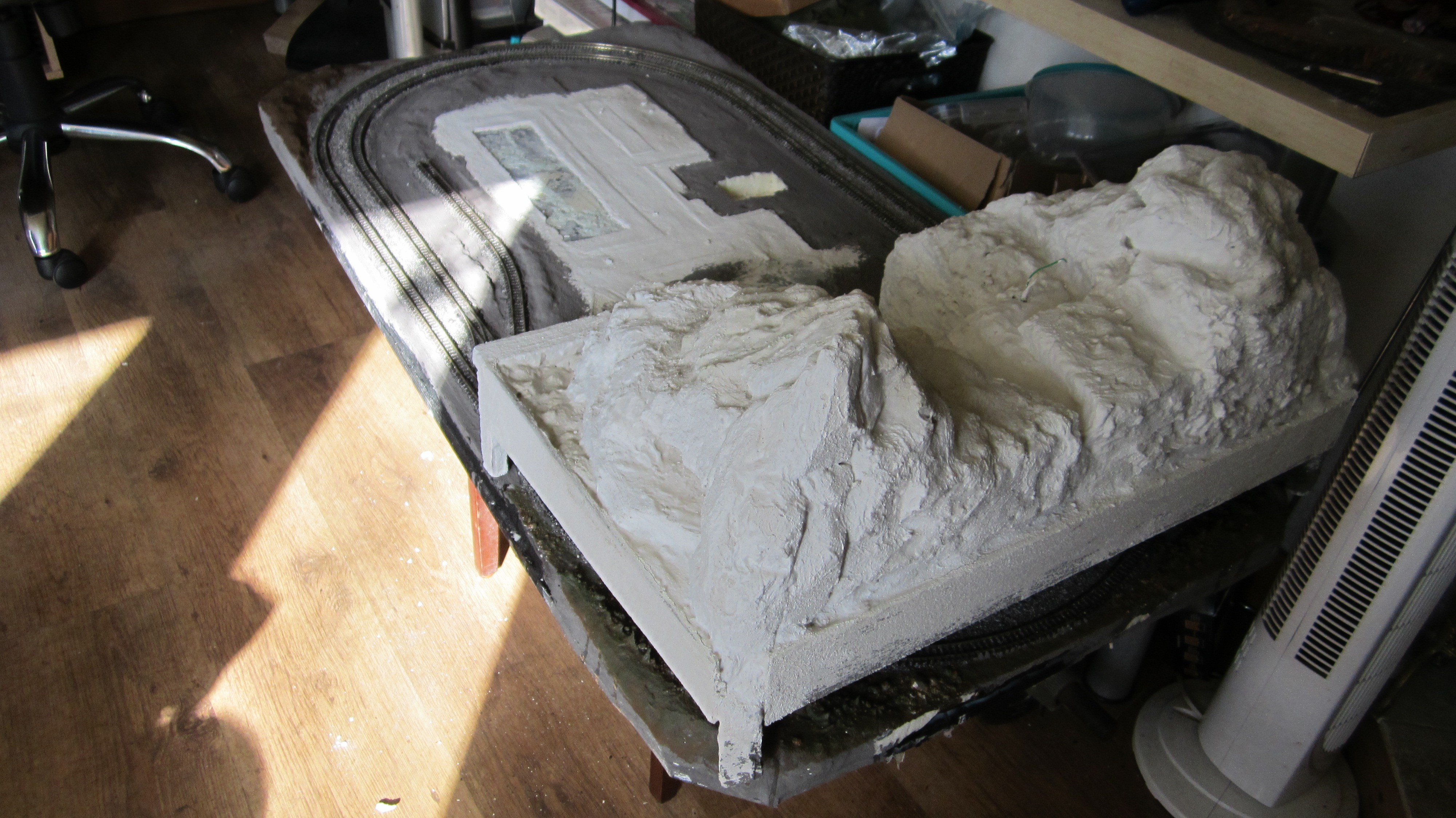
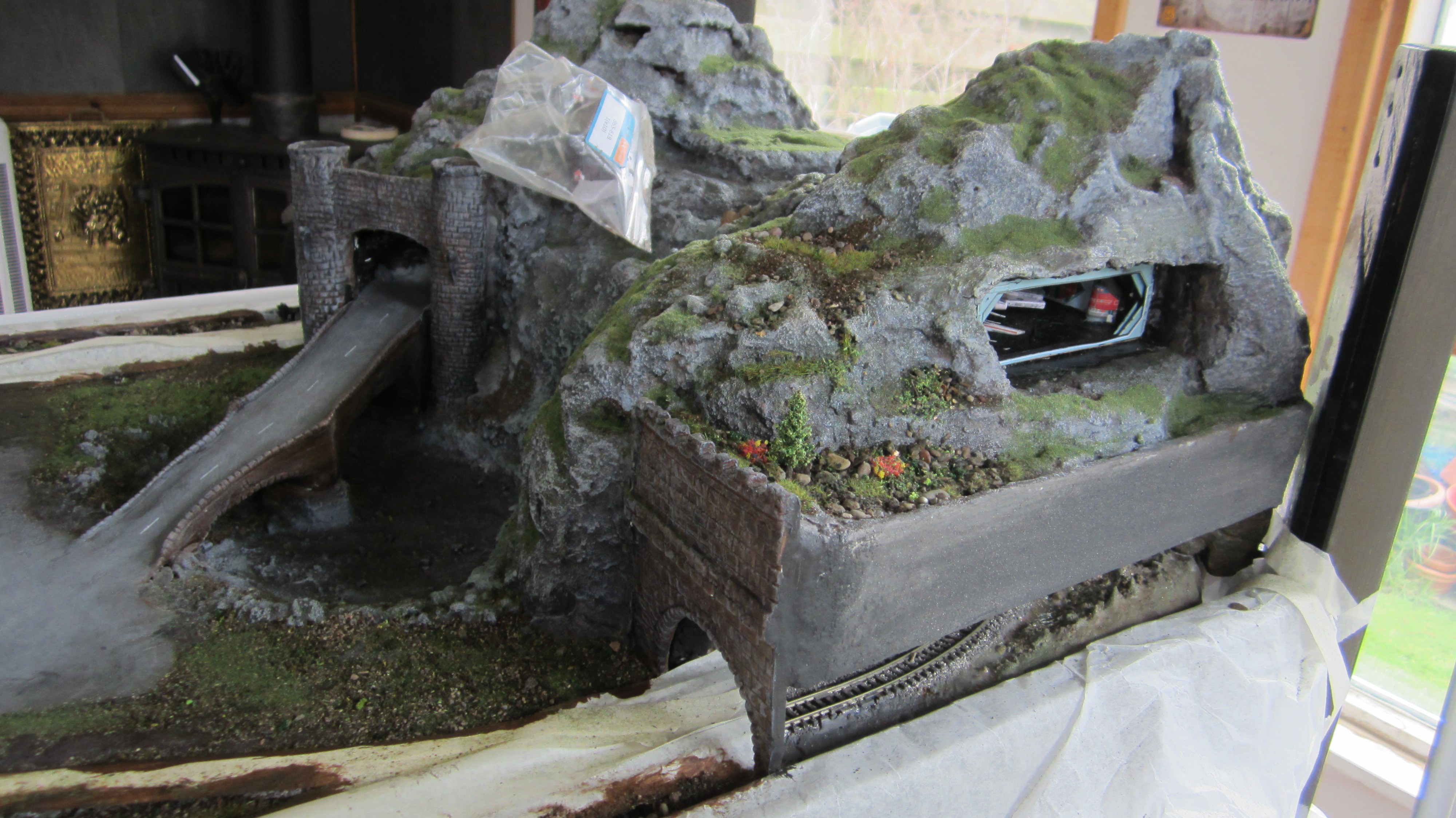
The new plan was to build the frame, mount the foam core to a plywood base, we could then run the wiring through and fit controller boards and power supply on the underside. This allowed us to develop the look of the hill and it was decided to expand the scenery into the void in the centre.
YouTube influences - Mel the Terrain Tutor - Luke APS - Luke Towan
We then soaked up modelling information and learned the following
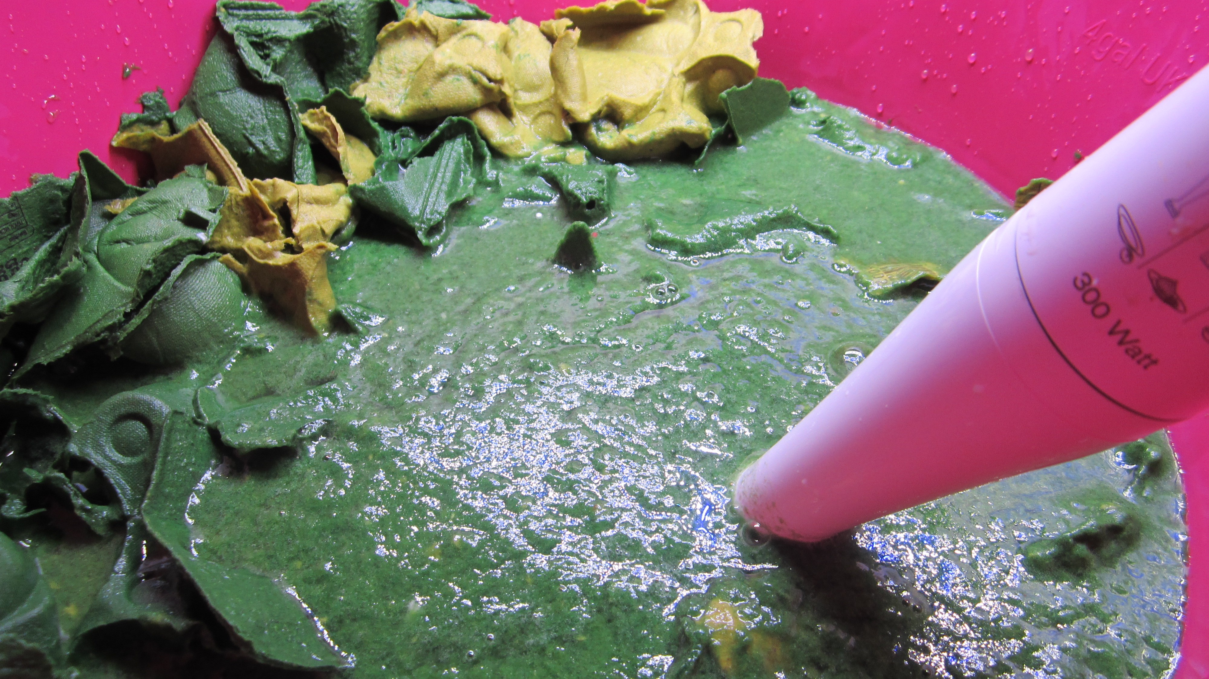
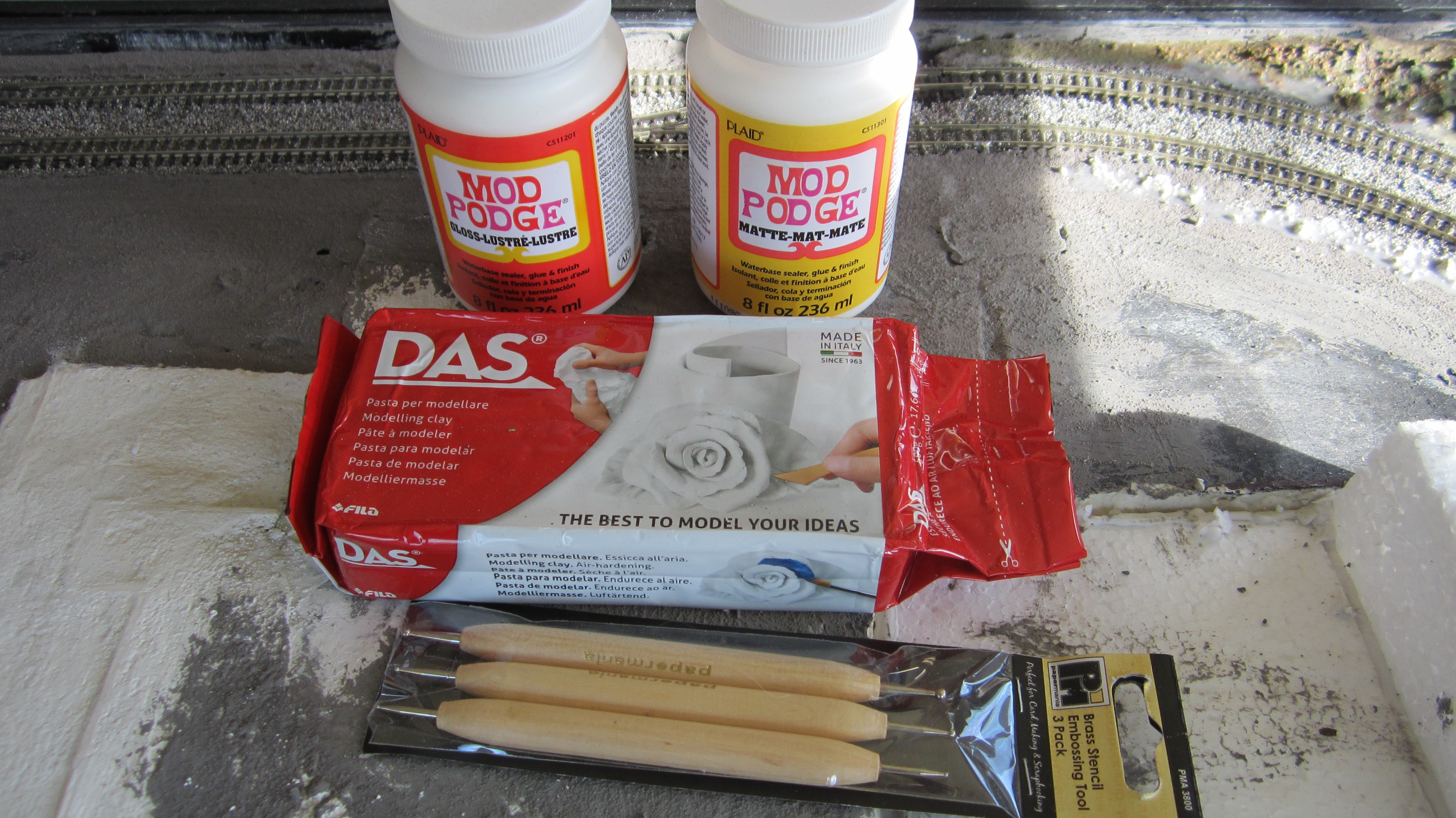
1. How to make Mod Podge for terrain modelling from egg boxes and plaster.
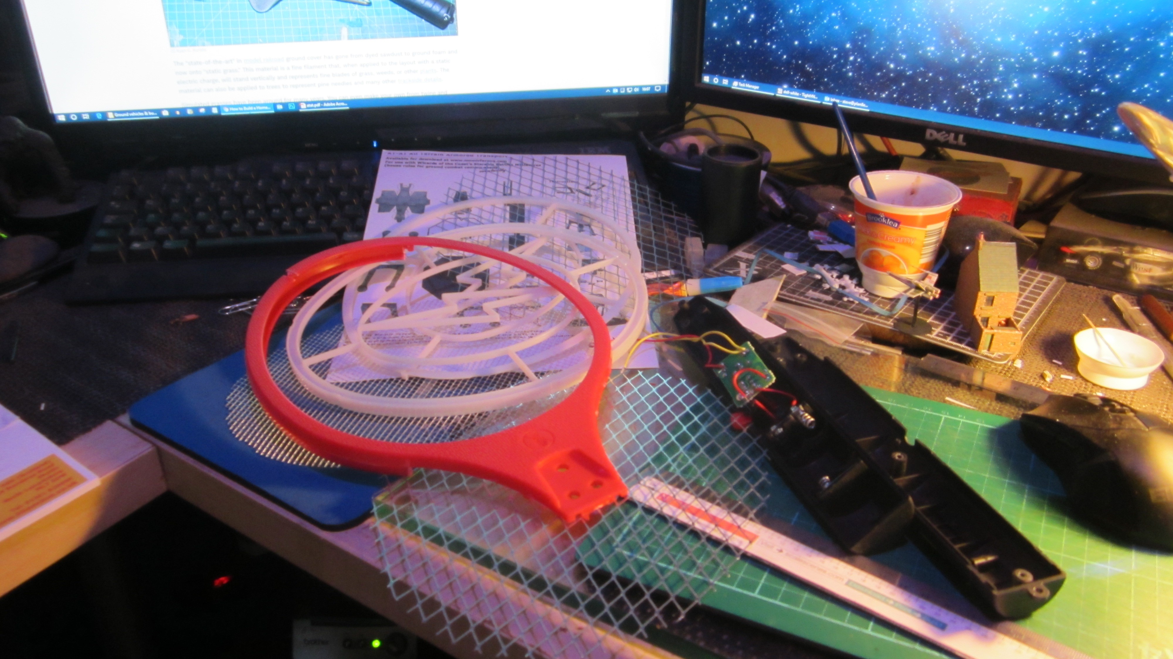
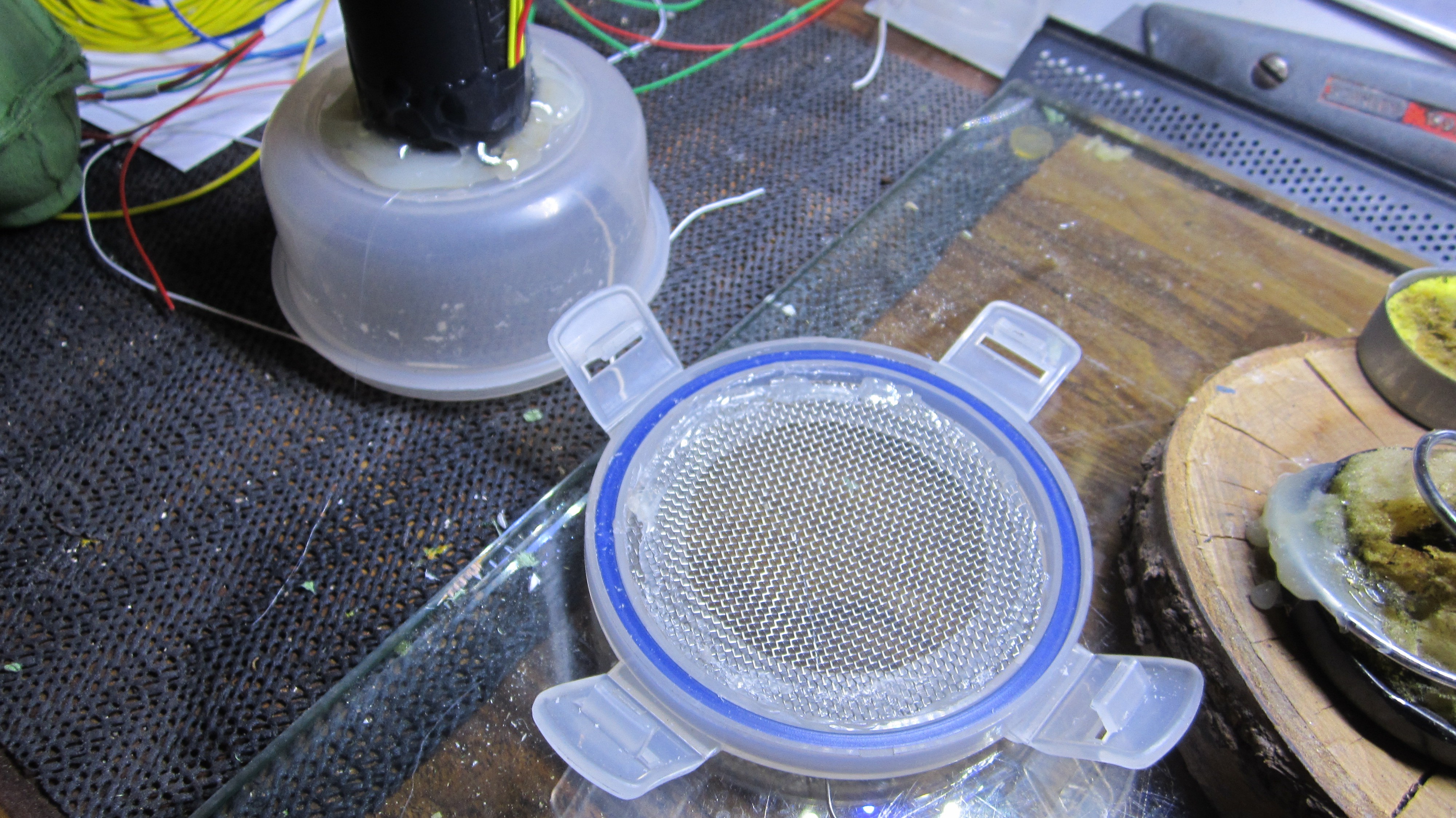
2. How to make a static grass applicator from a bug zapper.
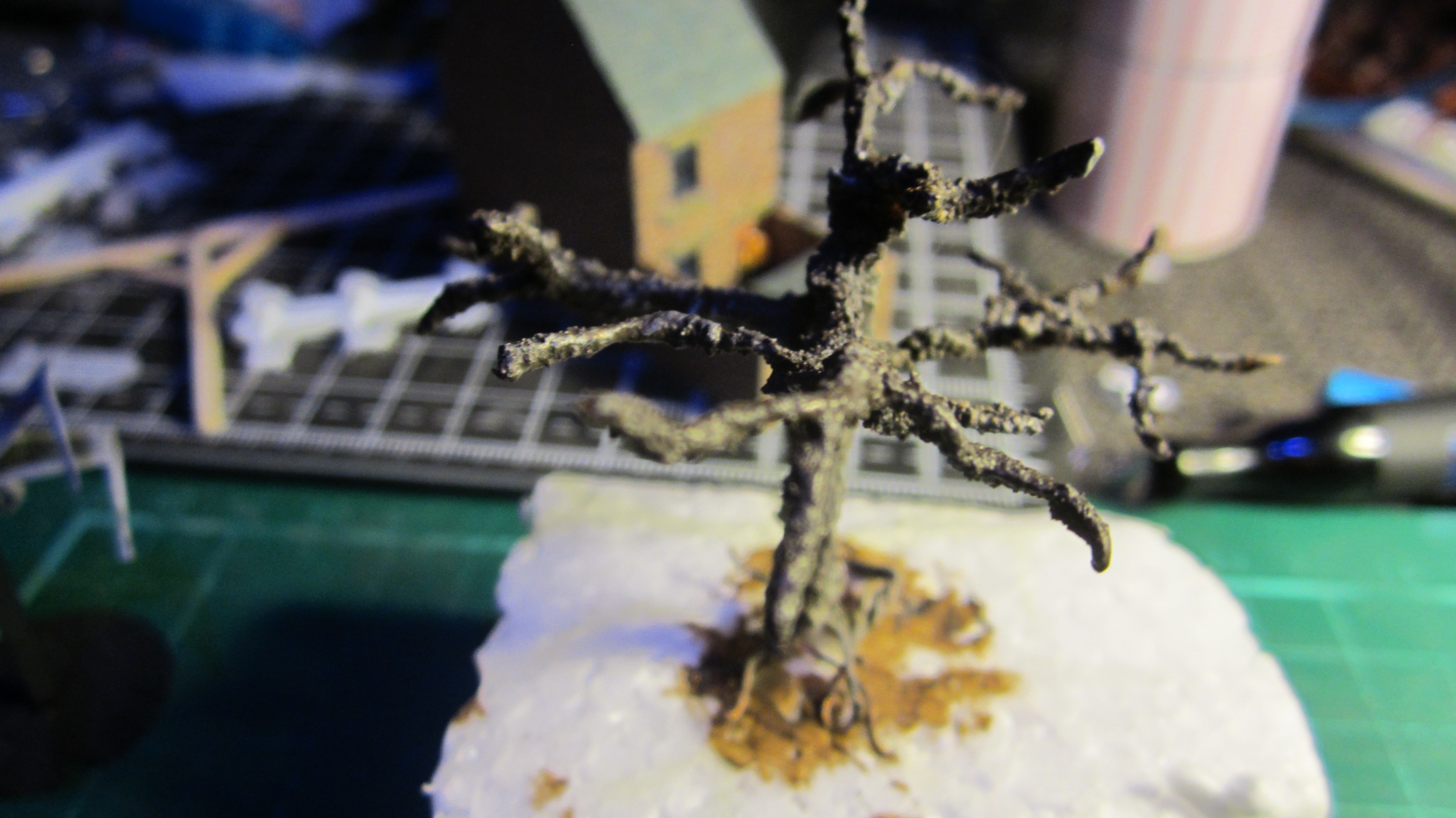
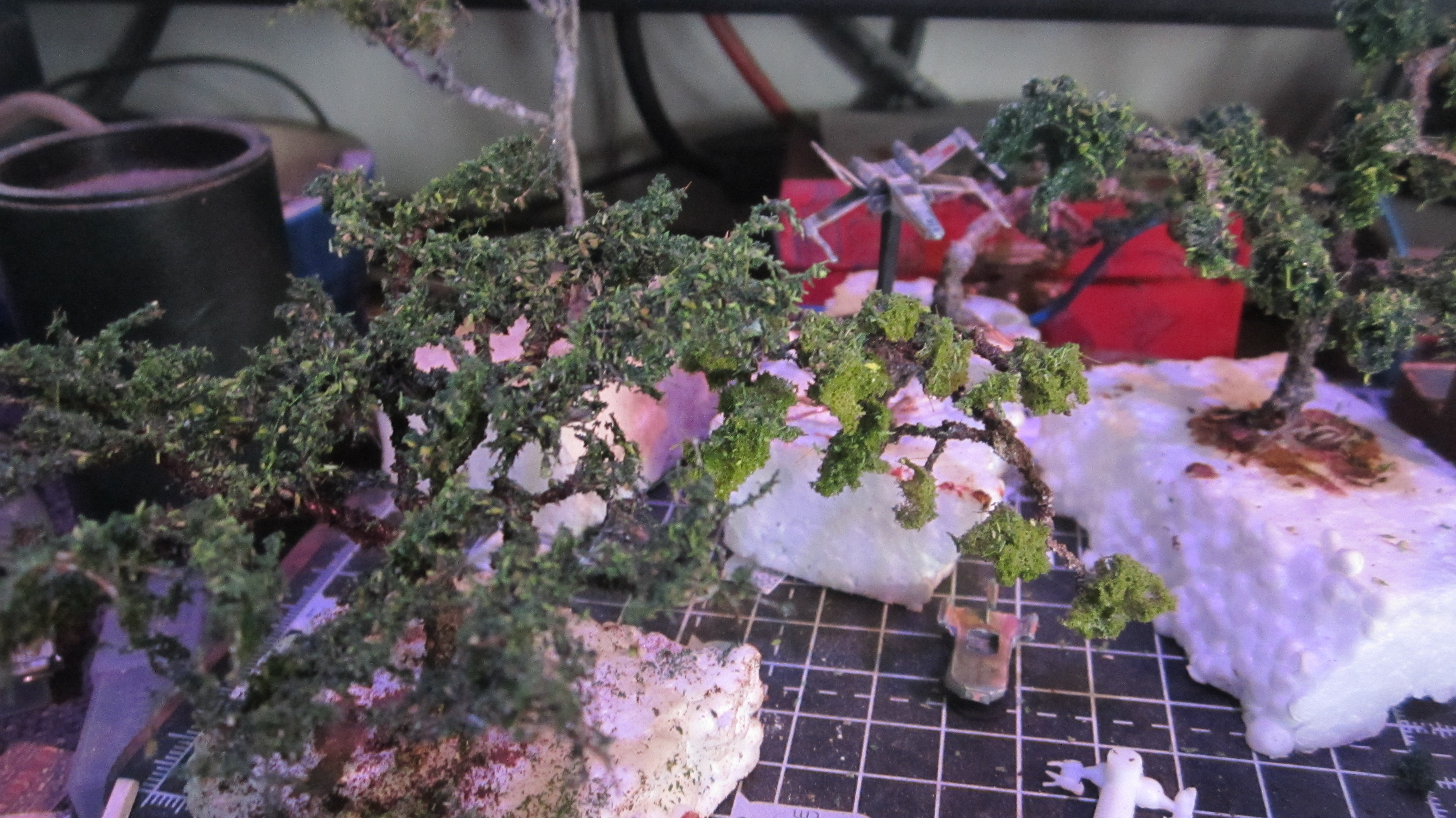
3. How to make trees with wire and coloured saw dust.
4. How to make a hot wire foam cutter.
5. How to make water with resin.
6. How to use Das air dry clay for structures.
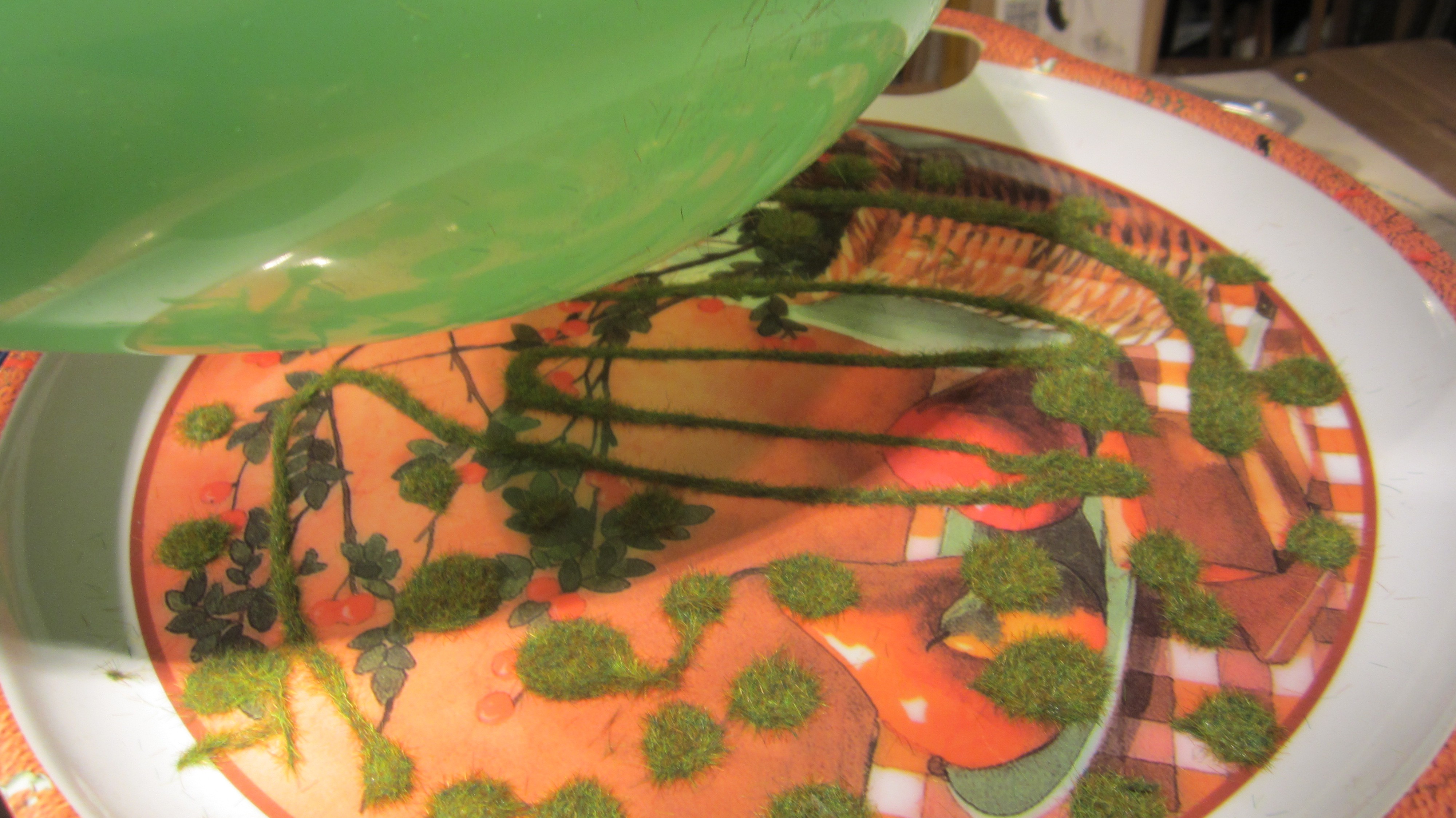
7. How to make bushes with aquarium plants.
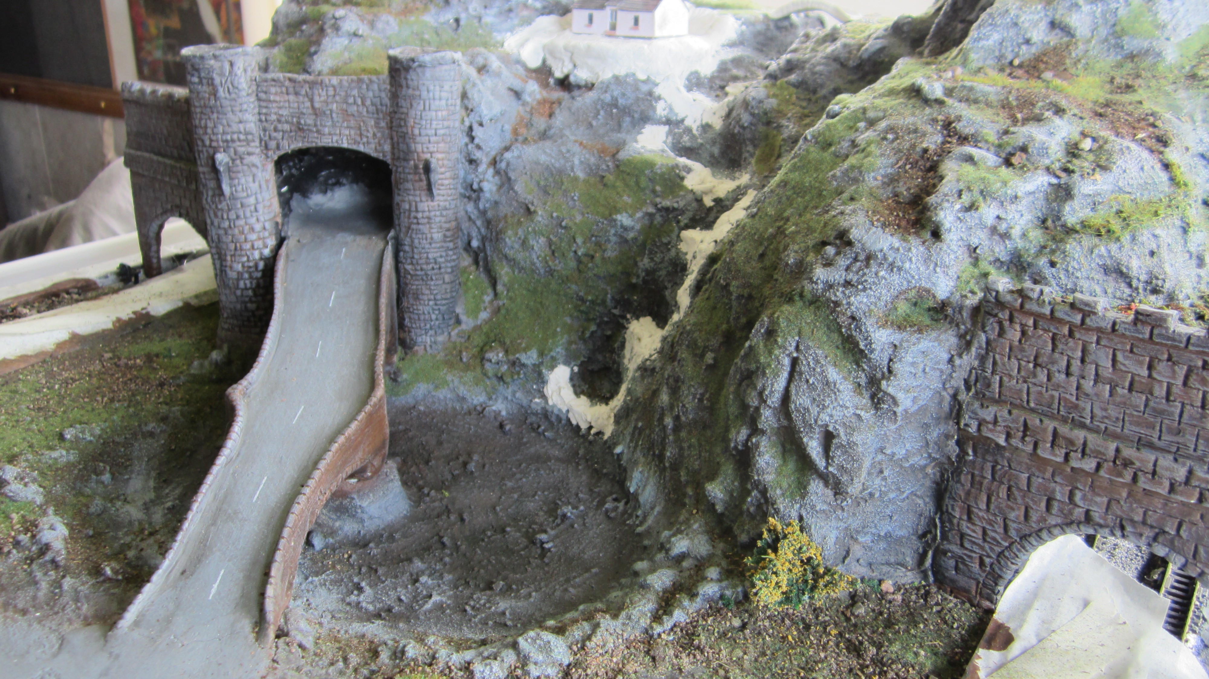
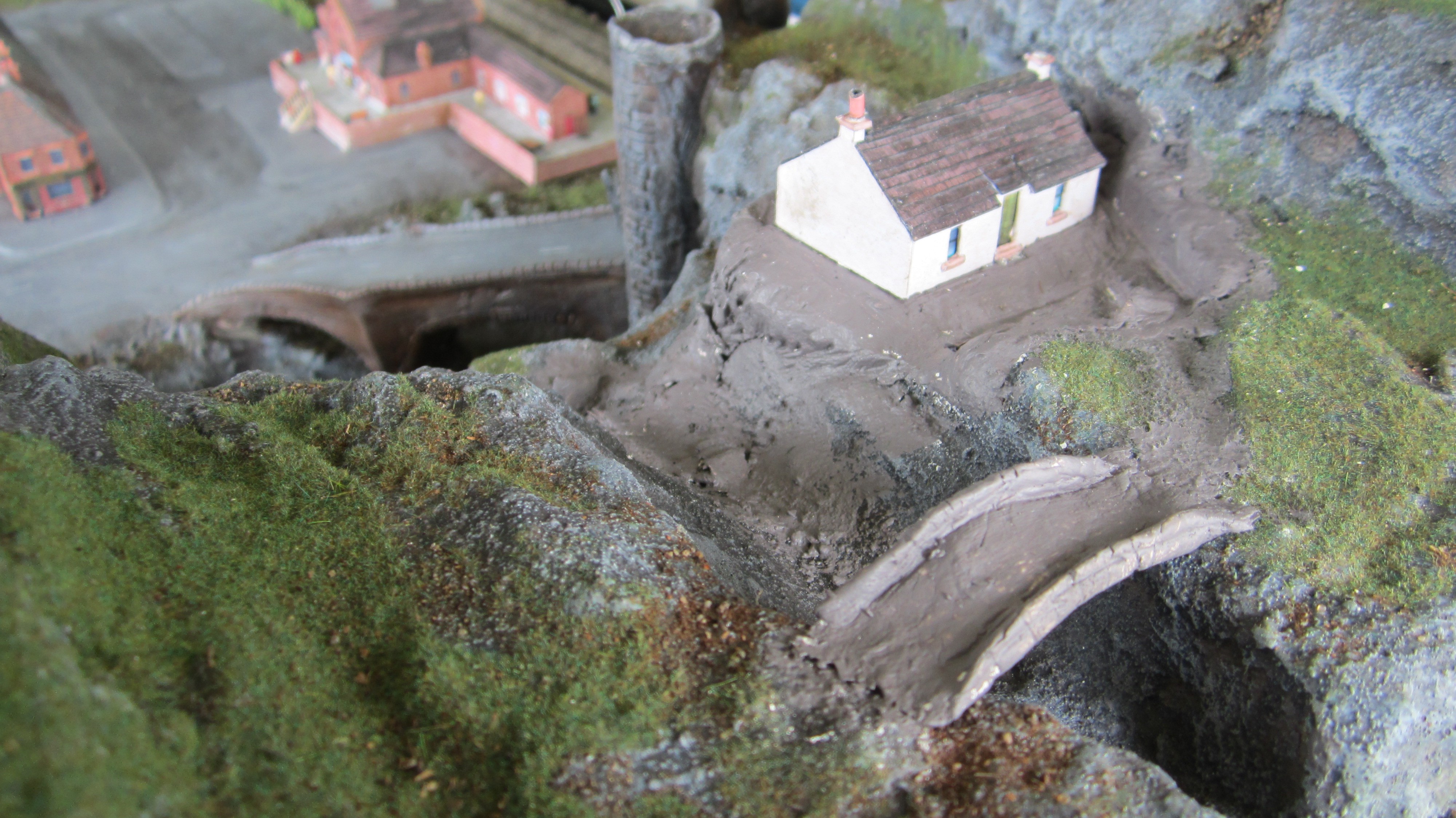
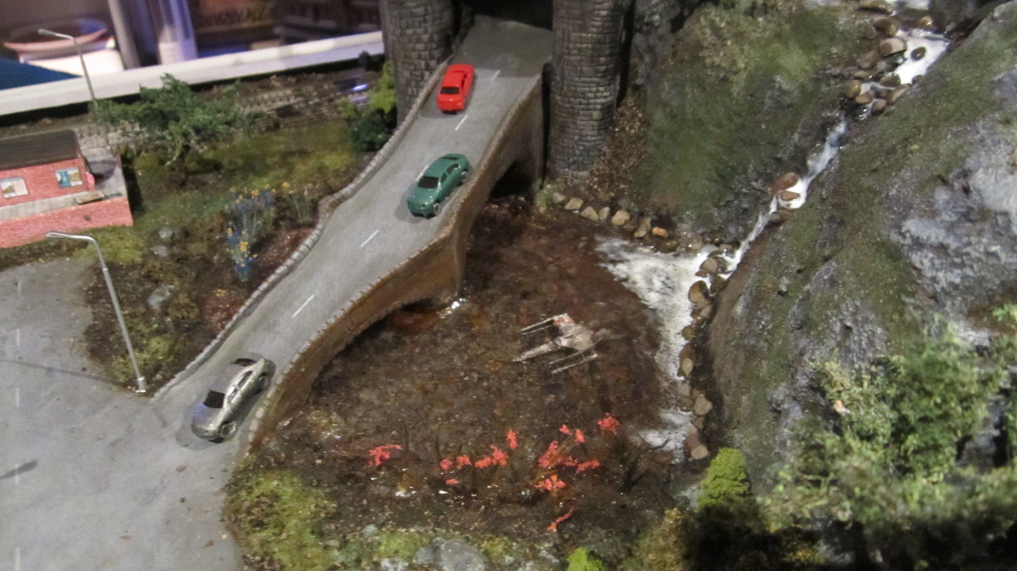
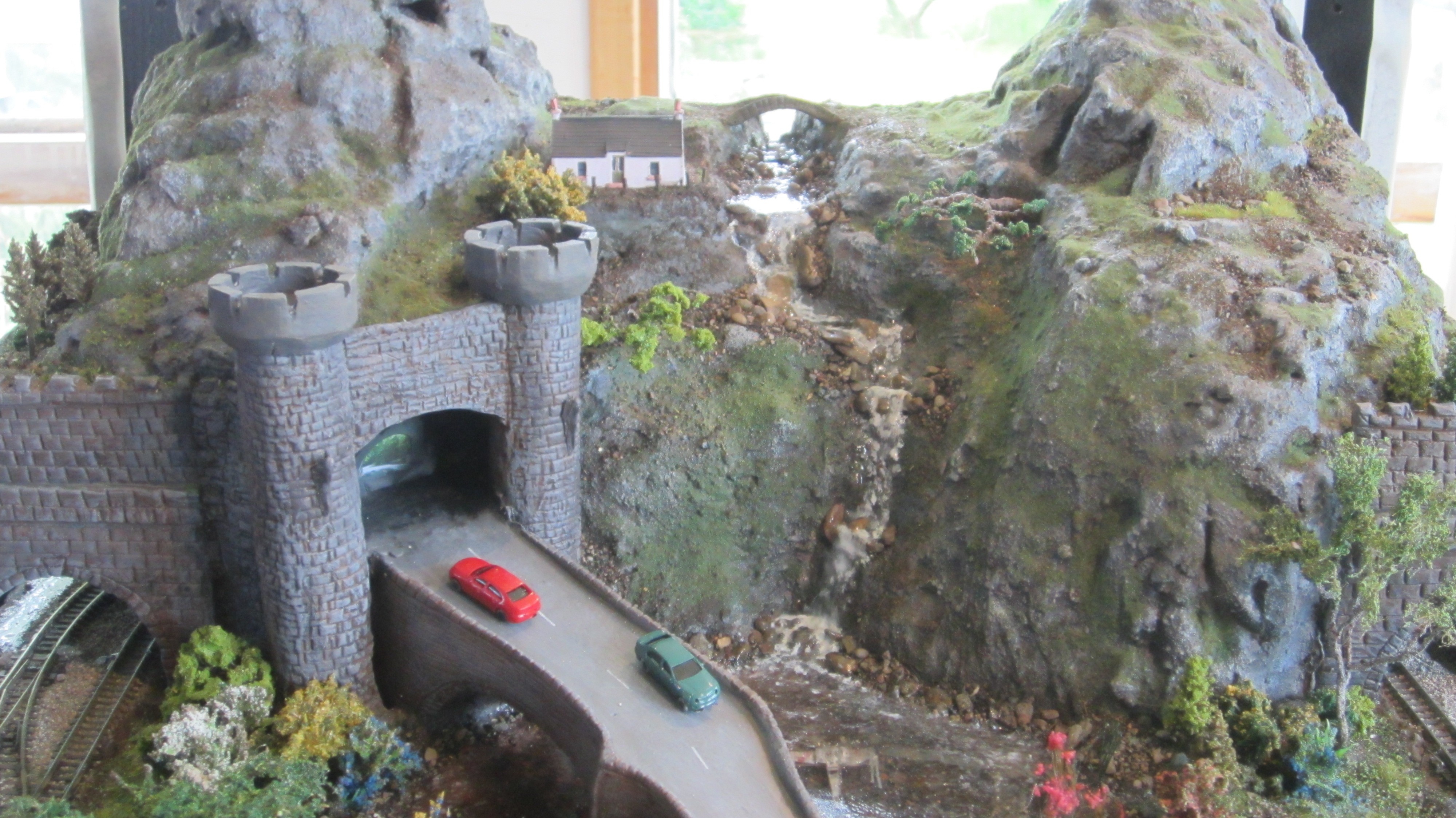
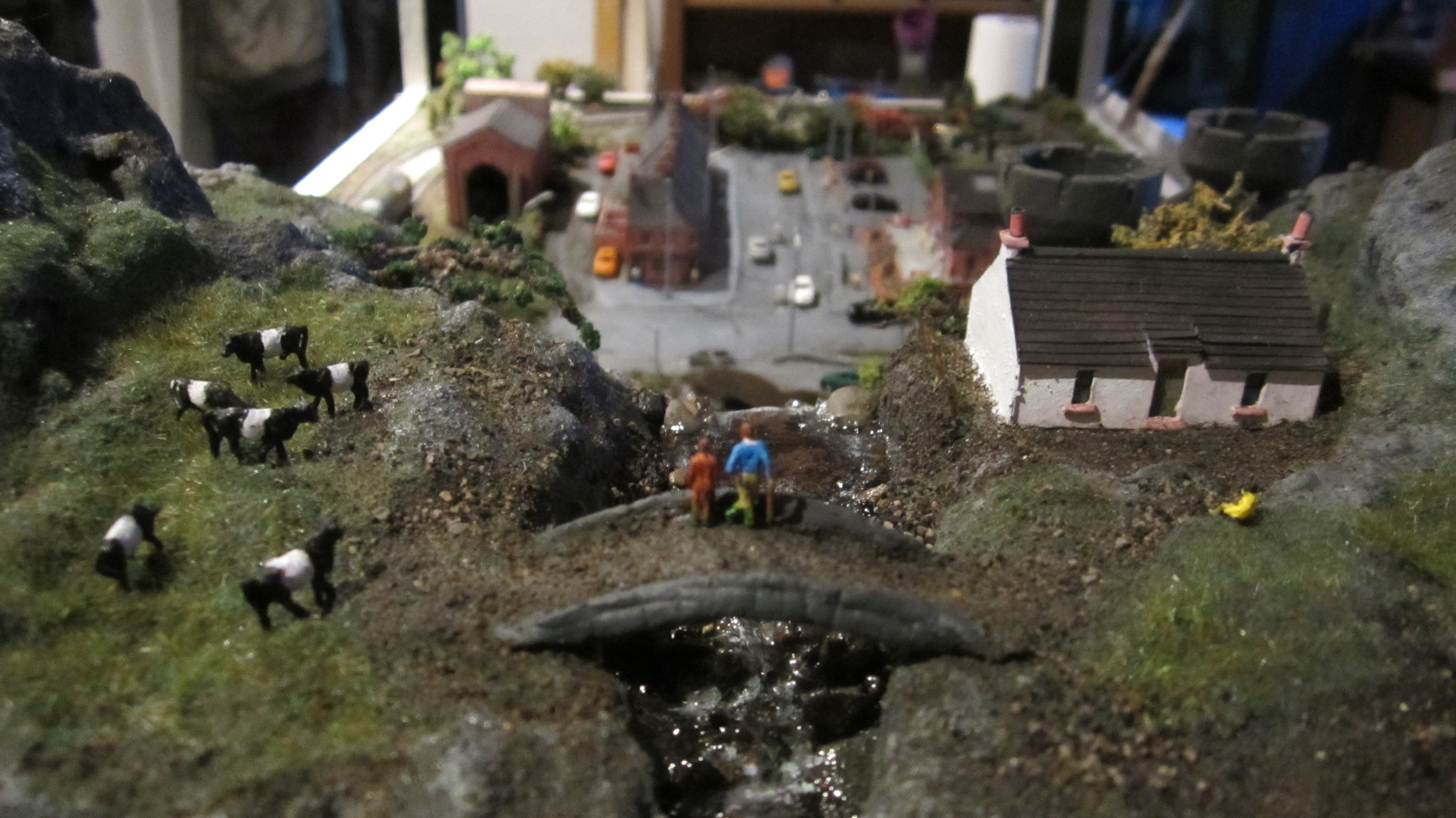
8. How to make waterfalls
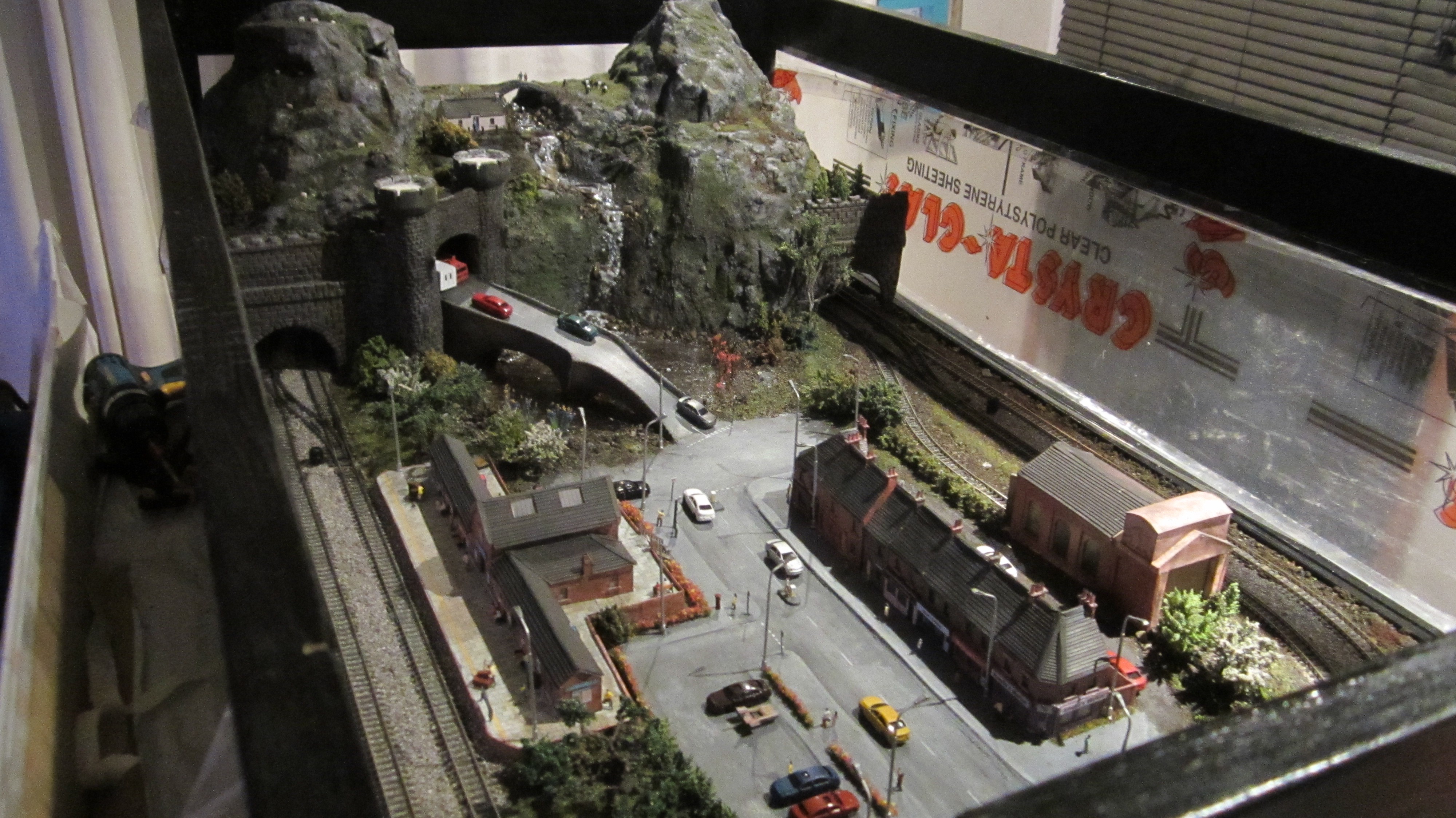
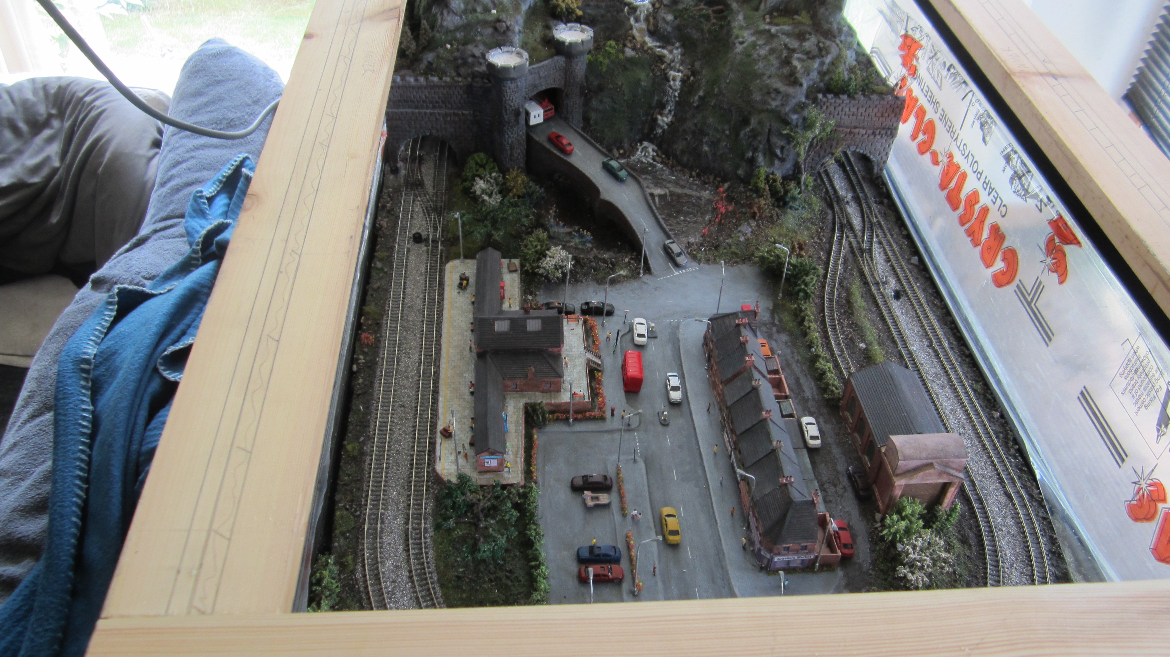
Nearly 6 months from the test run we have allowed our artistic side free rein and the table project is back on track (shameful pun I know)
We are really happy with the terrain and rebuild so far, we are now at the stage of finalising the electronics and completing the woodworking.
So it's been a long time since I last posted in December. We had a successful first run of the table before it failed spectacularly and we lost the ability to light up the leds. Since then the electronics have stalled but the work on the layout has been amazing. It's truely a work of art and looks amazing. I'm hoping we find the time to get some proper details put up because the amount of work in the artistic side of the layout is shocking.
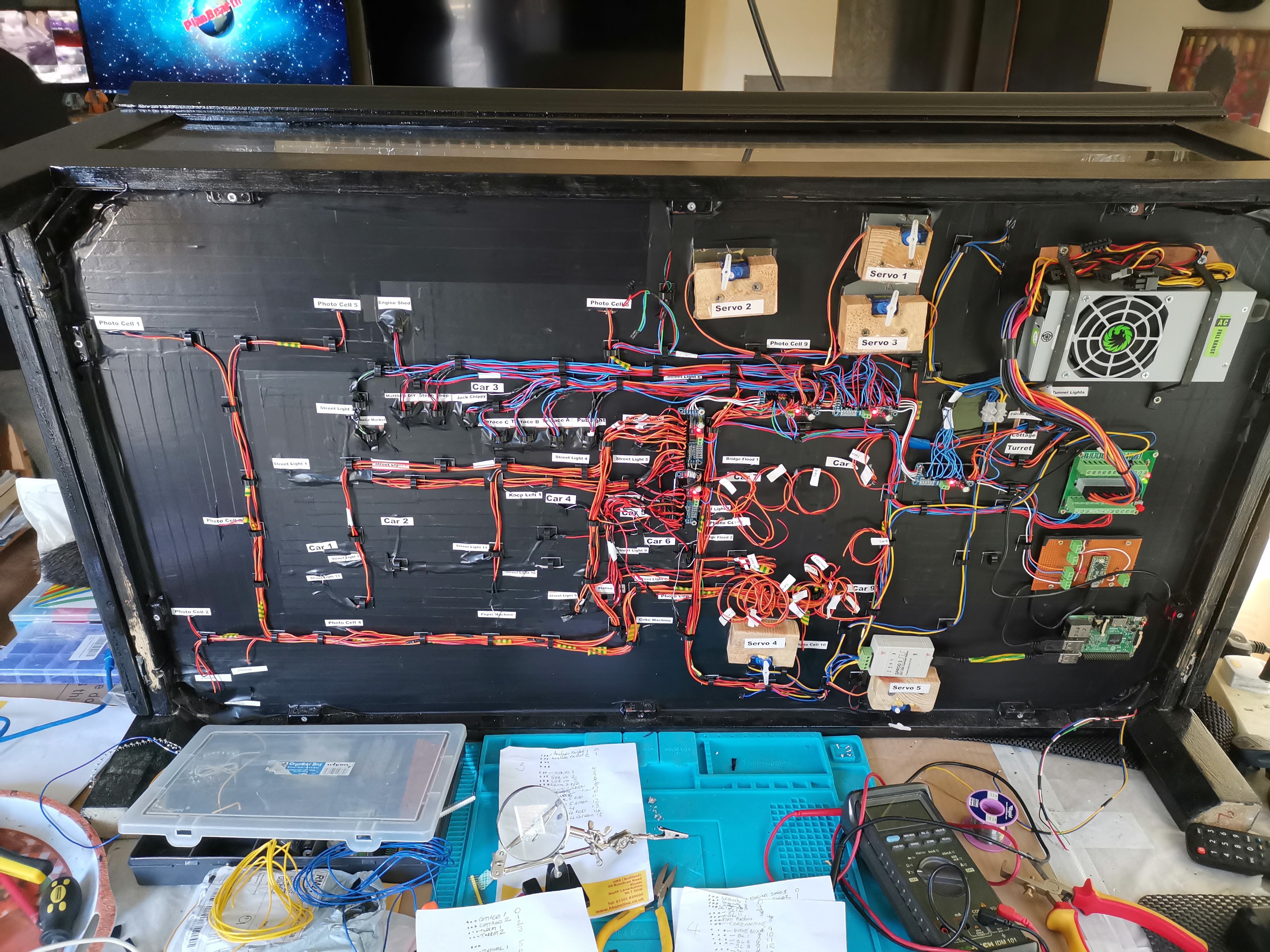
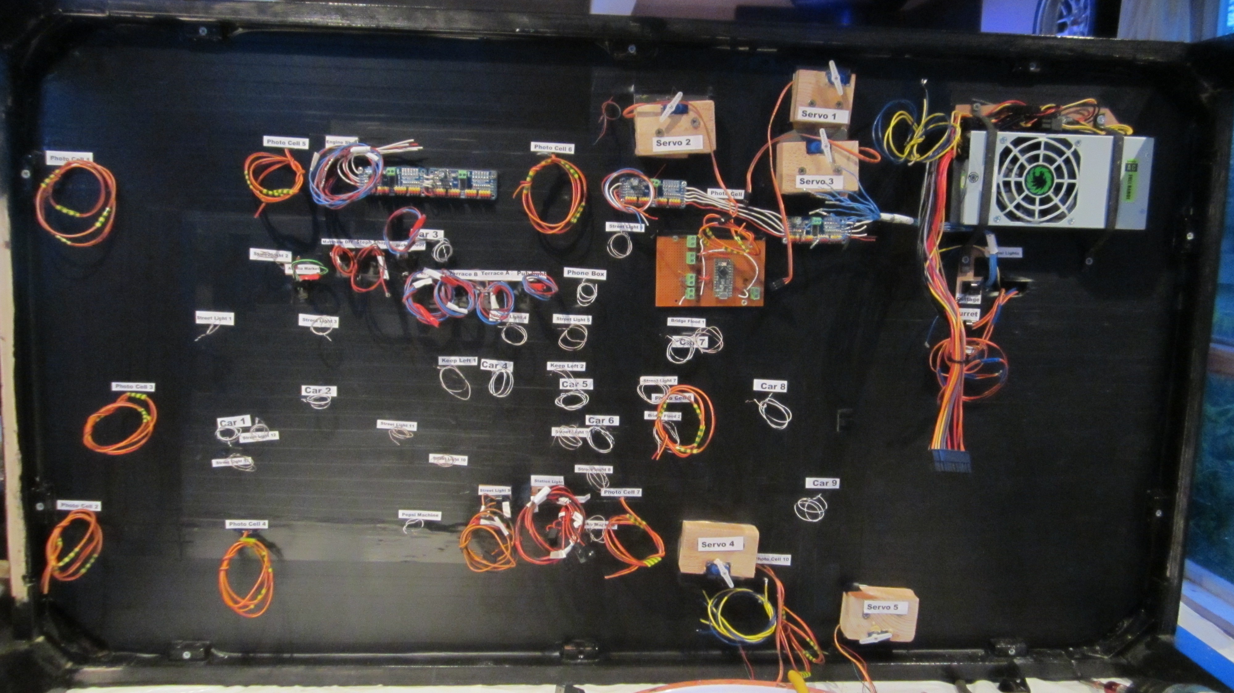
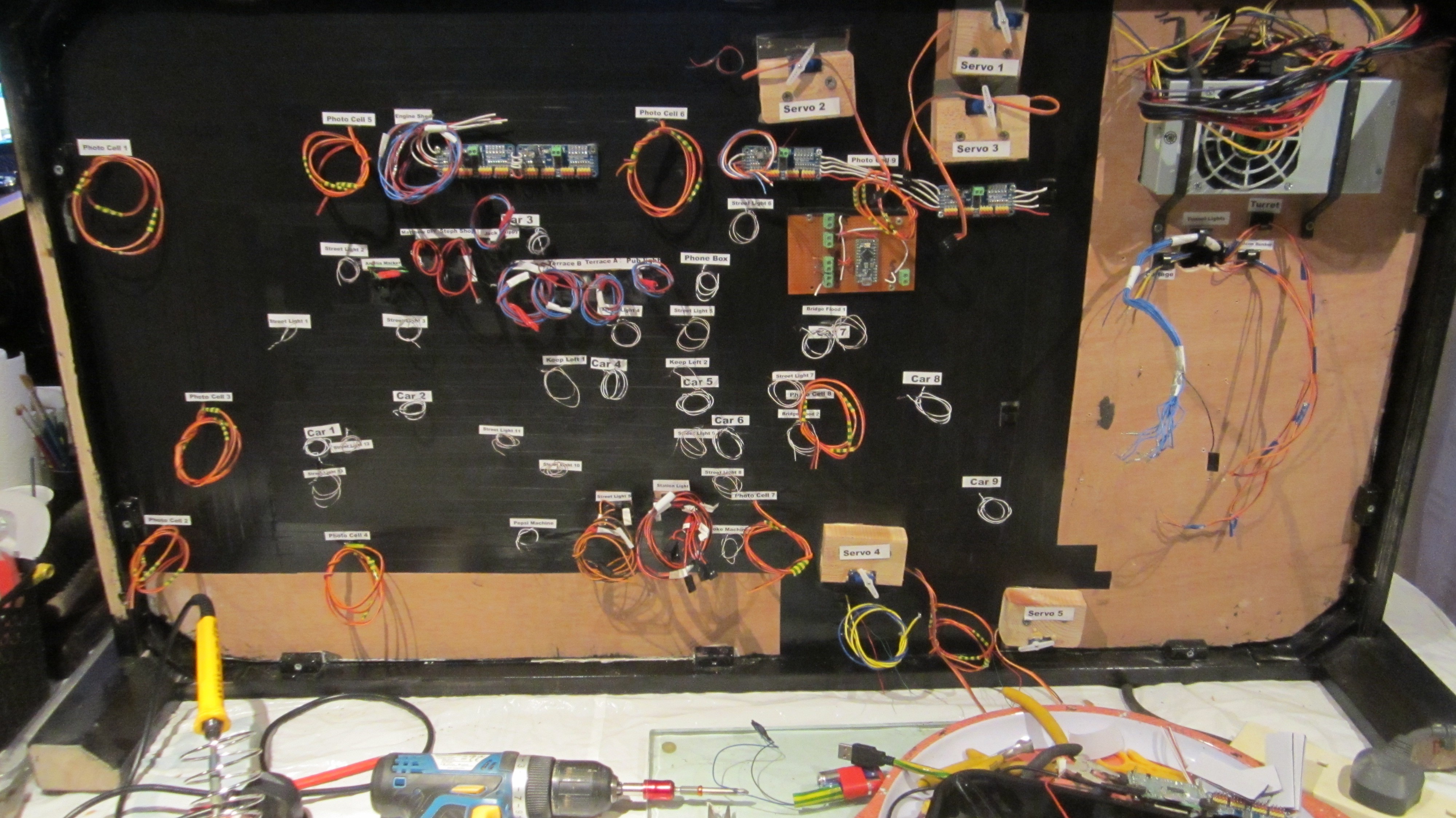
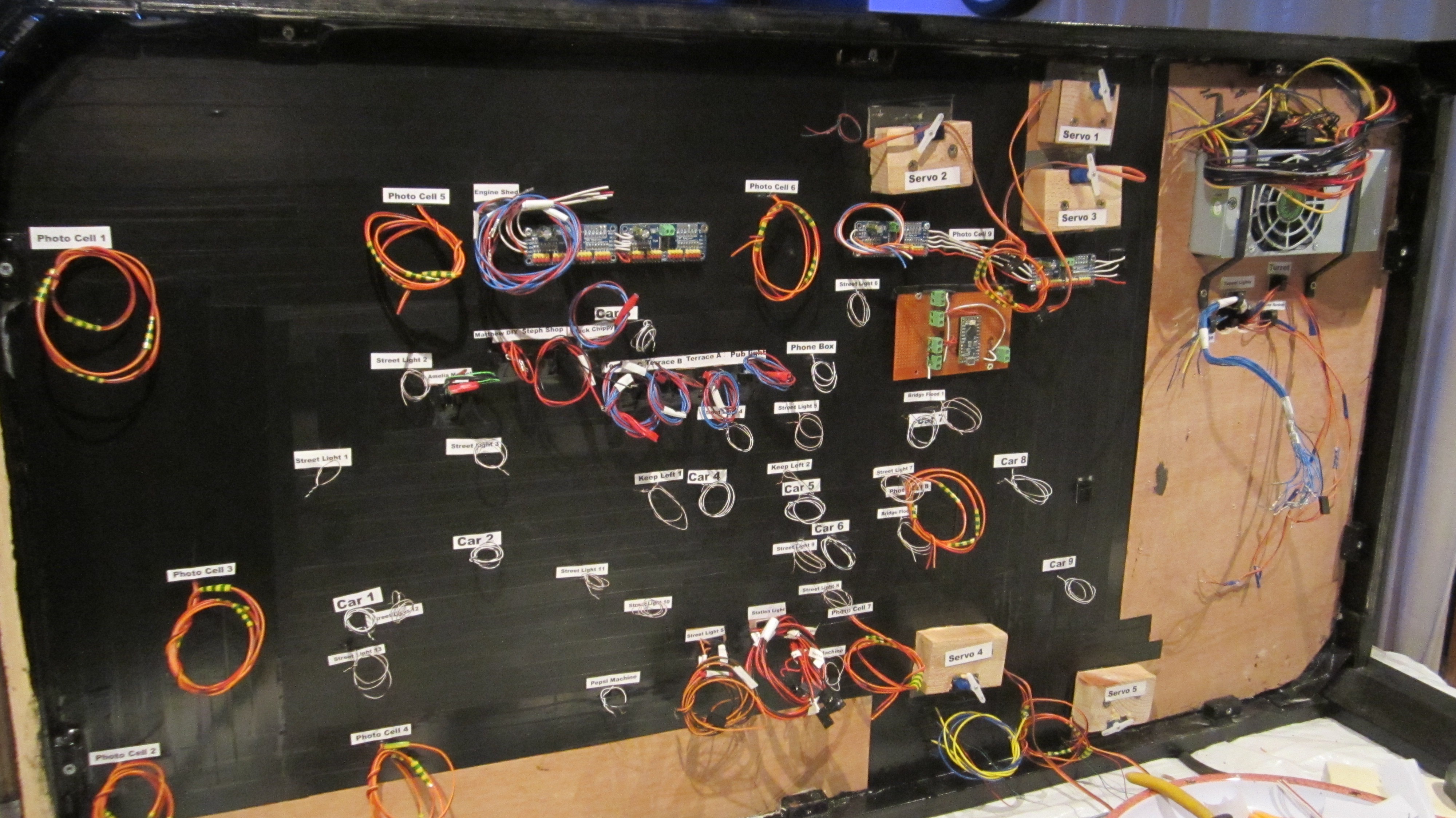
Now that the majority of the paint,gravel, clay, paper, and everything else has been put down we've been able to build a complete picture of the final numbers for the electronics.
| Item | Qty |
| Single Colour LEDs | 69 |
| Car Series LEDs | 10 |
| Servos | 5 |
| Photoresistors | 10 |
This also includes 1 Raspberry Pi, a Teensy LC as well as a strip of 5v RGB LED Strip Lighting. I need to get onsite to setup the voltage control for some of the leds as we're using a PC ATX power supply to get 12v and 5v and I need to PWM the 12v for the Car LEDs. The Cars come premade with a set of 4 leds in series with a current limiting resistor. Because the LEDs are in series we need a higher (12v) voltage to cover the voltage drop of the 4 leds.
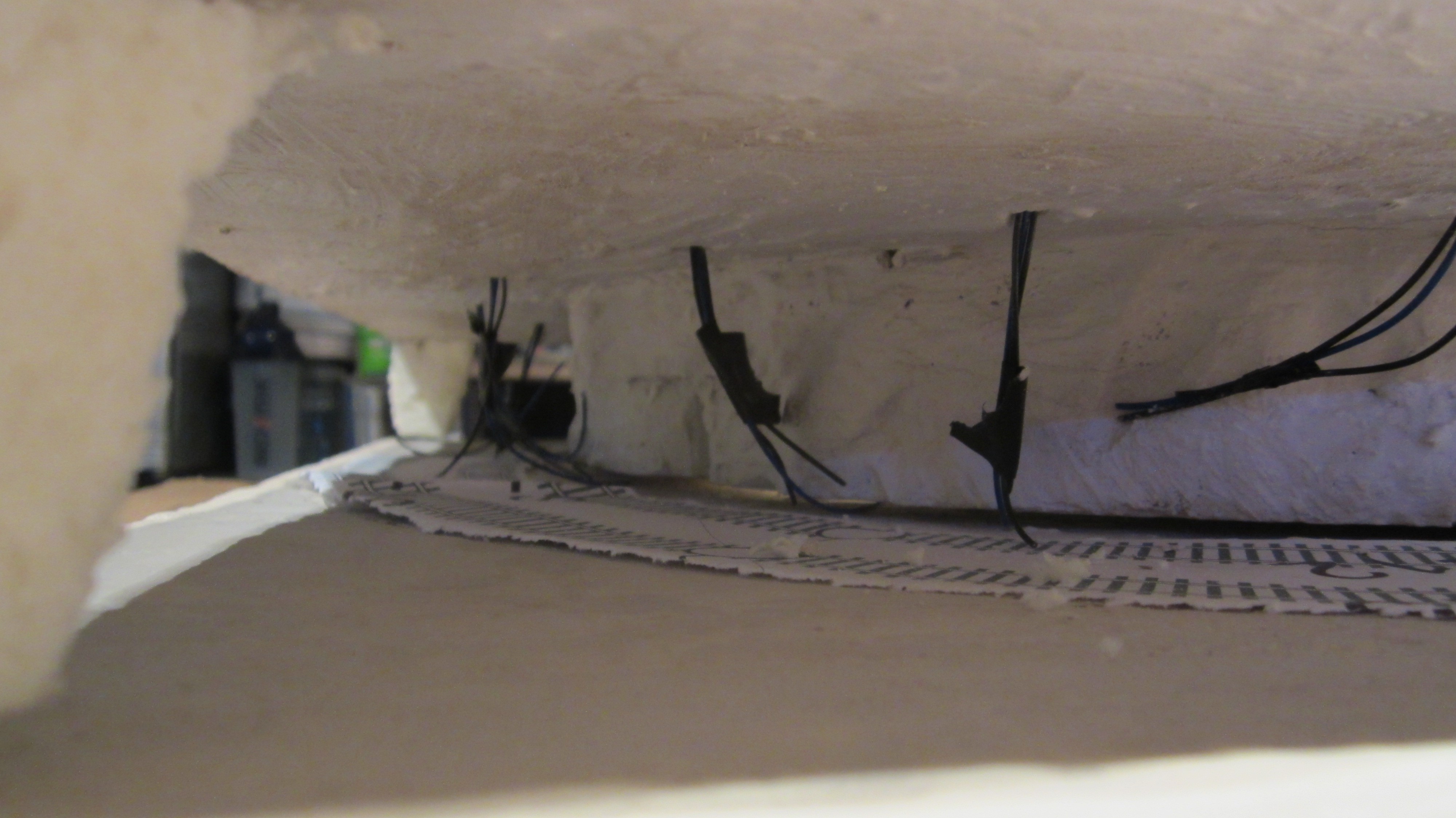
Some pics of under the table;
Light at the end of the tunnel
OK! loads of progress to update on, it's been a while since I have had a chance to do this entry on the terrain.
The tunnel grouting turned out OK, I have learned a lot about terrain building from Mel the Terrain Tutor, he has a great resource on YouTube and I encourage anyone wanting to find out more to visit his channel https://www.youtube.com/channel/UCx_aro8CTHw7ZD5H661hC6Q
He has some brilliant ideas and hacks about making your own materials and well explained tutorials on landscaping that I have borrowed from heavily as you will see from the next few log entries.
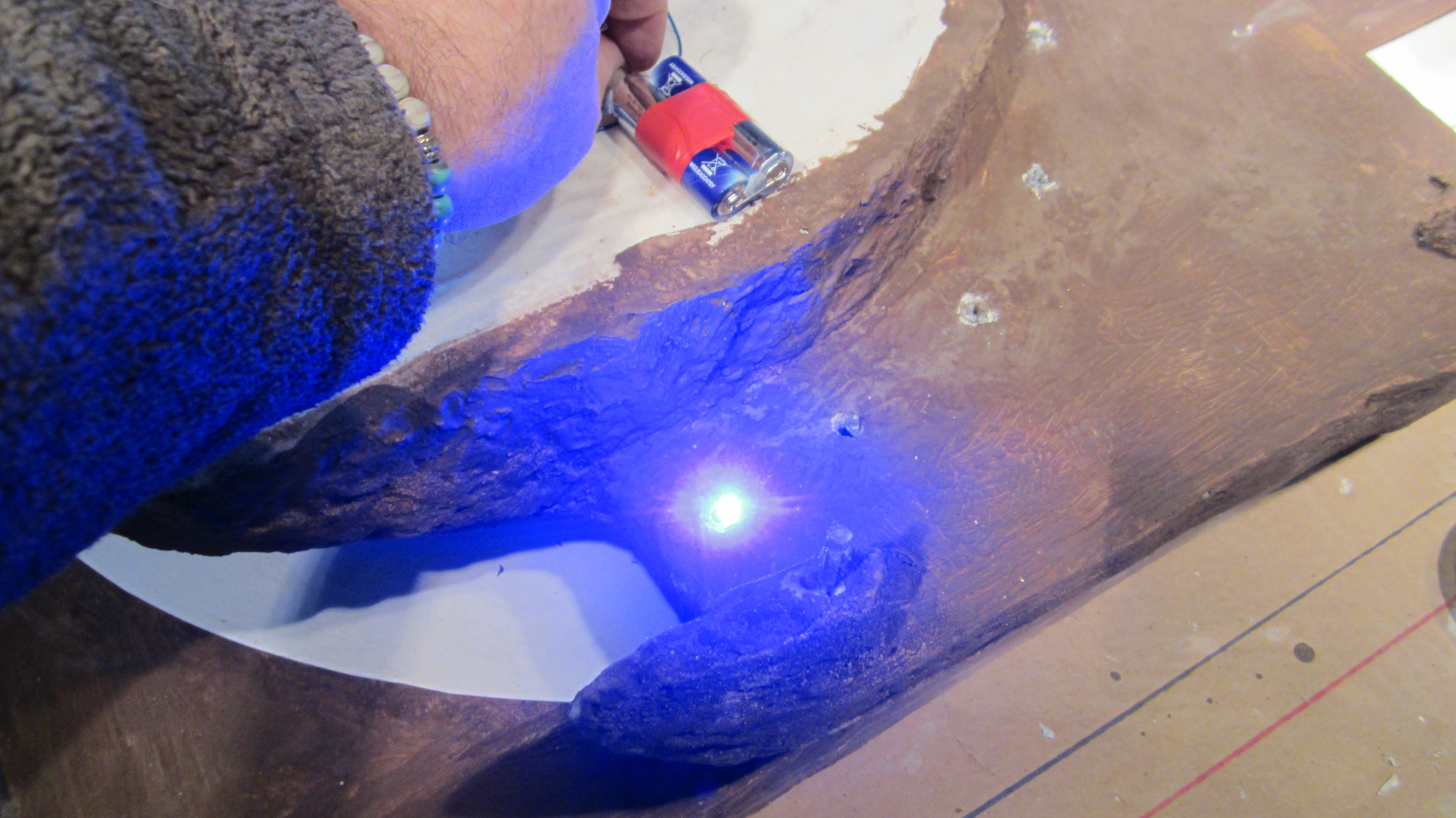
But first to catch up, the tunnel was just begging for some lights and at that point I wired it for led's, the intention was to have white light but I didn't notice until I had them in position and was able to test them that I realised they were blue.
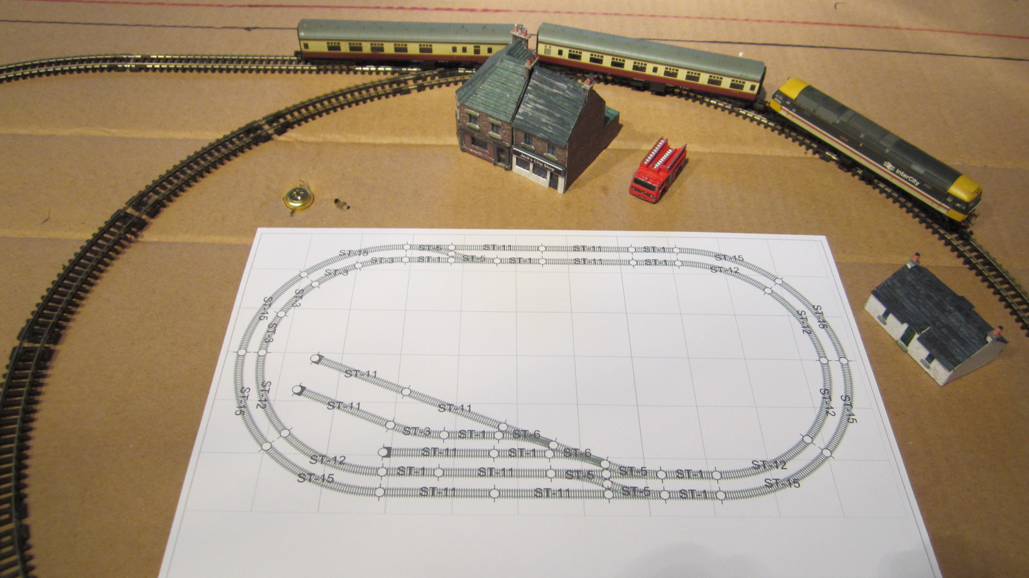
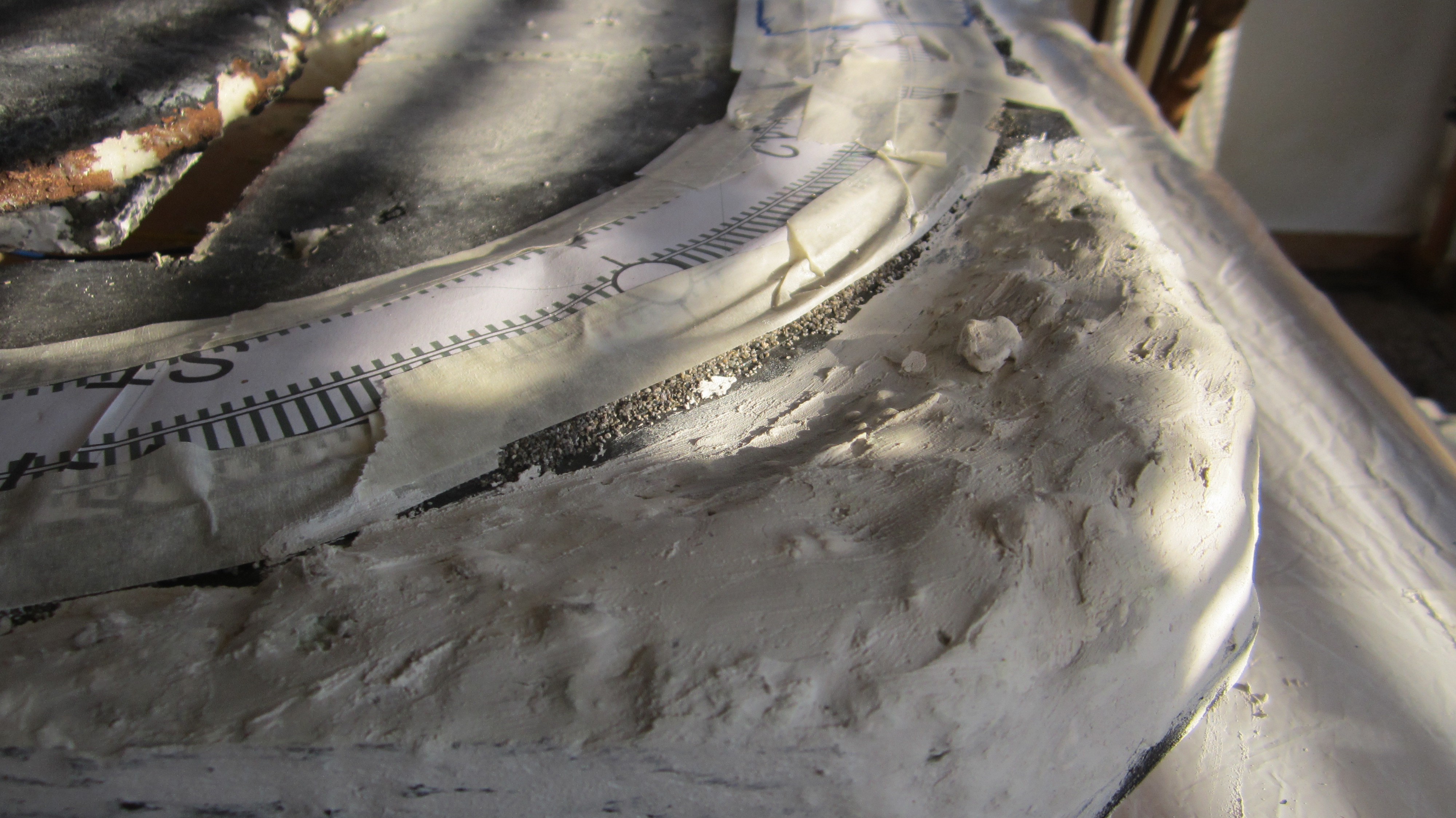
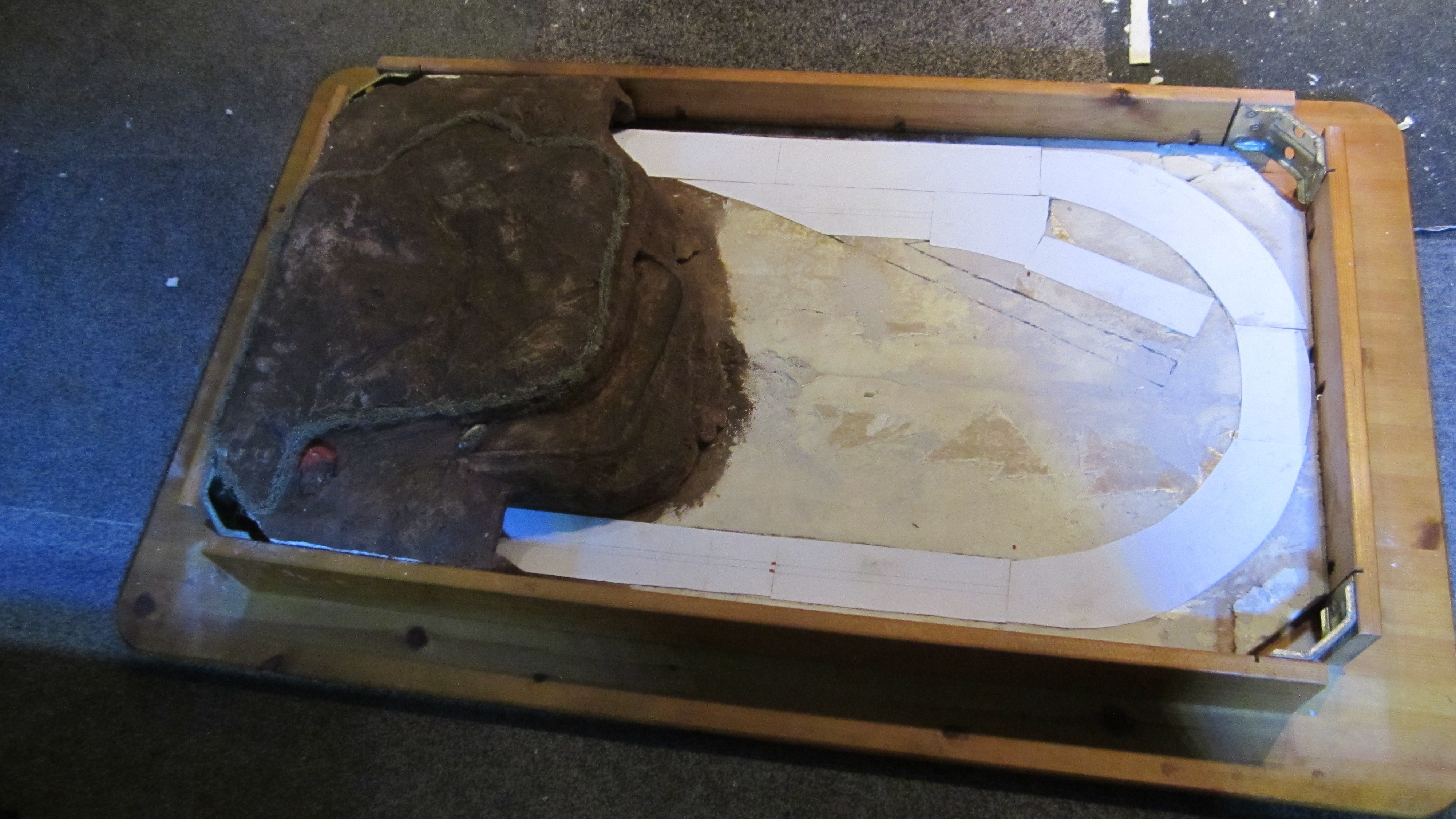
I printed a full size track layout using AnyRail v6.16 DRail Modelspoor Software (Trial Version), a resource that has proven really useful when planning a model railway.
The full size track layout was a useful guide for checking the tunnel for clearances.
What the Flock!
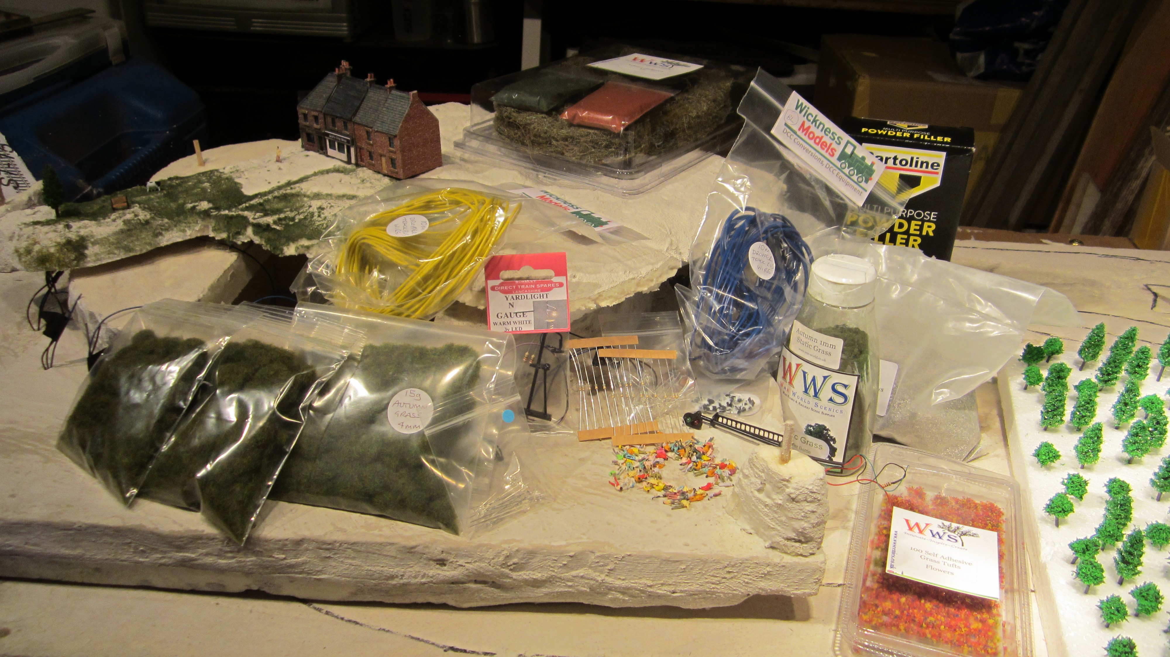
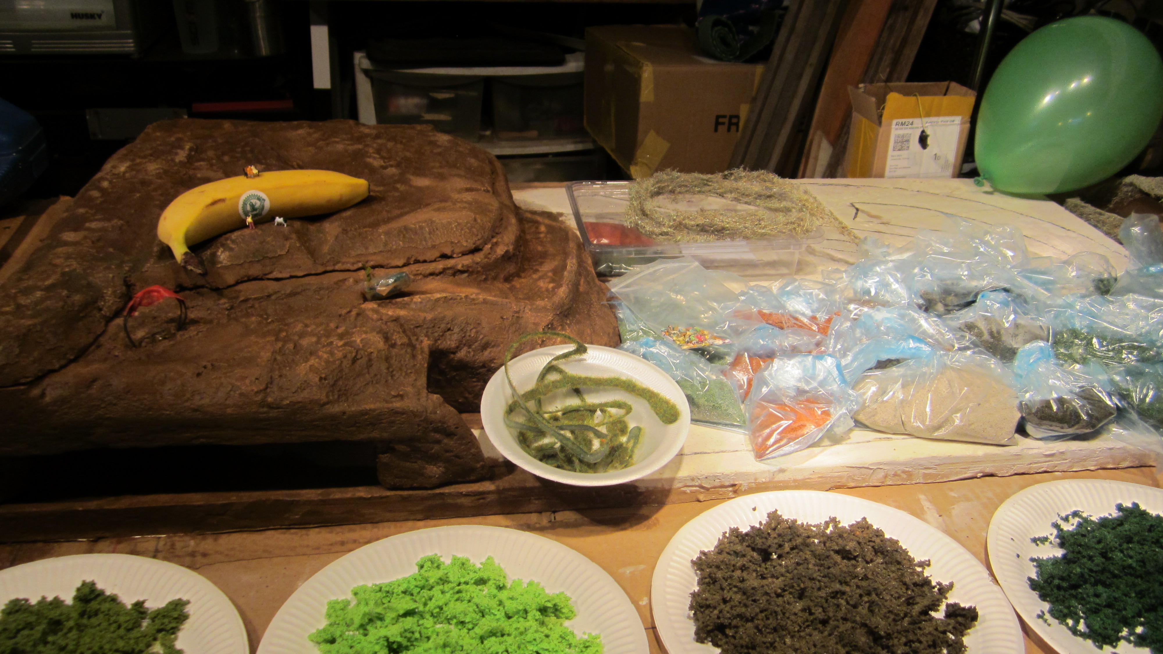
It was time to get on the internet and get some materials for the next stage, this is where I quickly realised how expensive the materials for model making were, I bought some small items (literally!) to get the feel for the scale and experiment with.
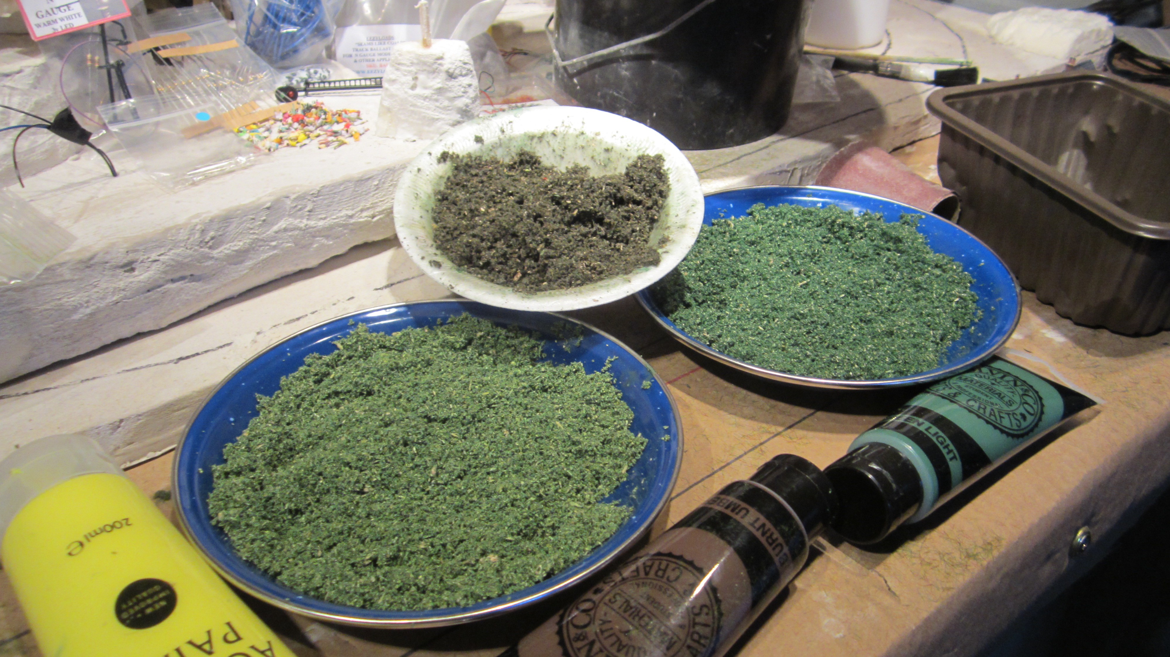
This is when Mel The Terrain Tutor came in, and I began creating my own flock and foliage using sawdust, fish tank sand, and a sponge.
I looked at making a static grass applicator but did't have the time or budget to make one never mind buy one, so I went for the super budget version and a balloon rubbed on my jumper, I experimented with PVA glue on a plastic tray, I put blobs of PVA on the tray and chucked some static grass at it, then waved my static charged balloon over it, looks OK and will do for now, cheap and cheerful.
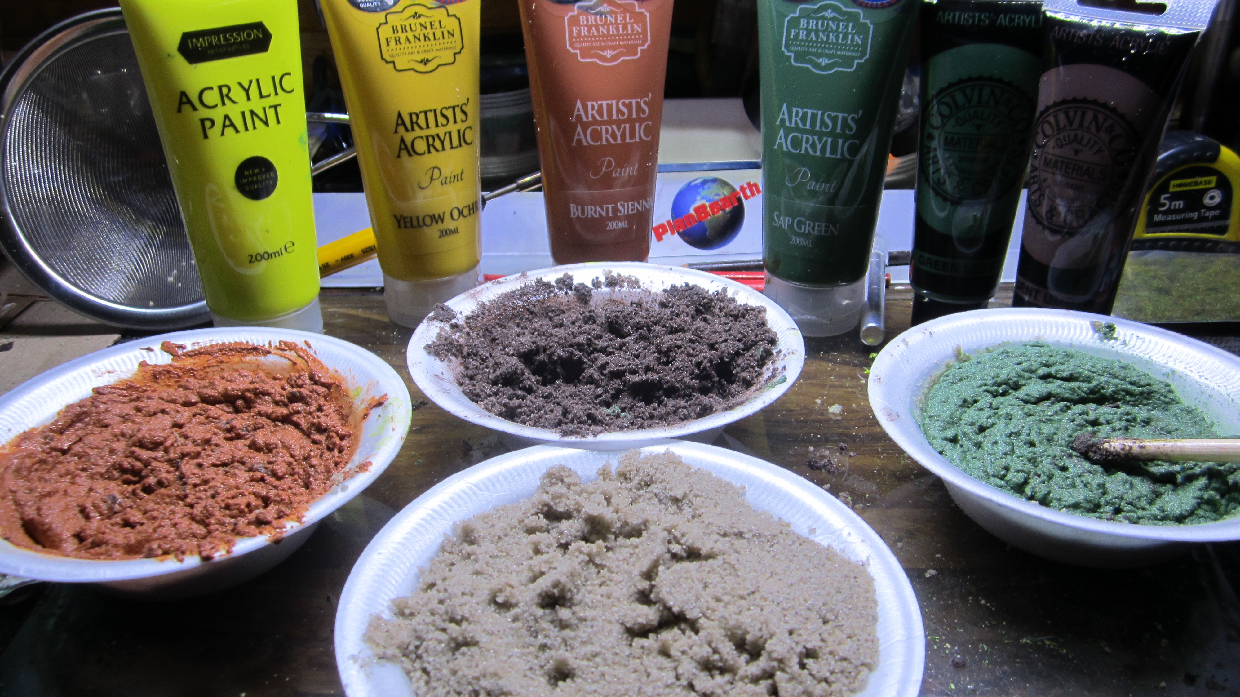
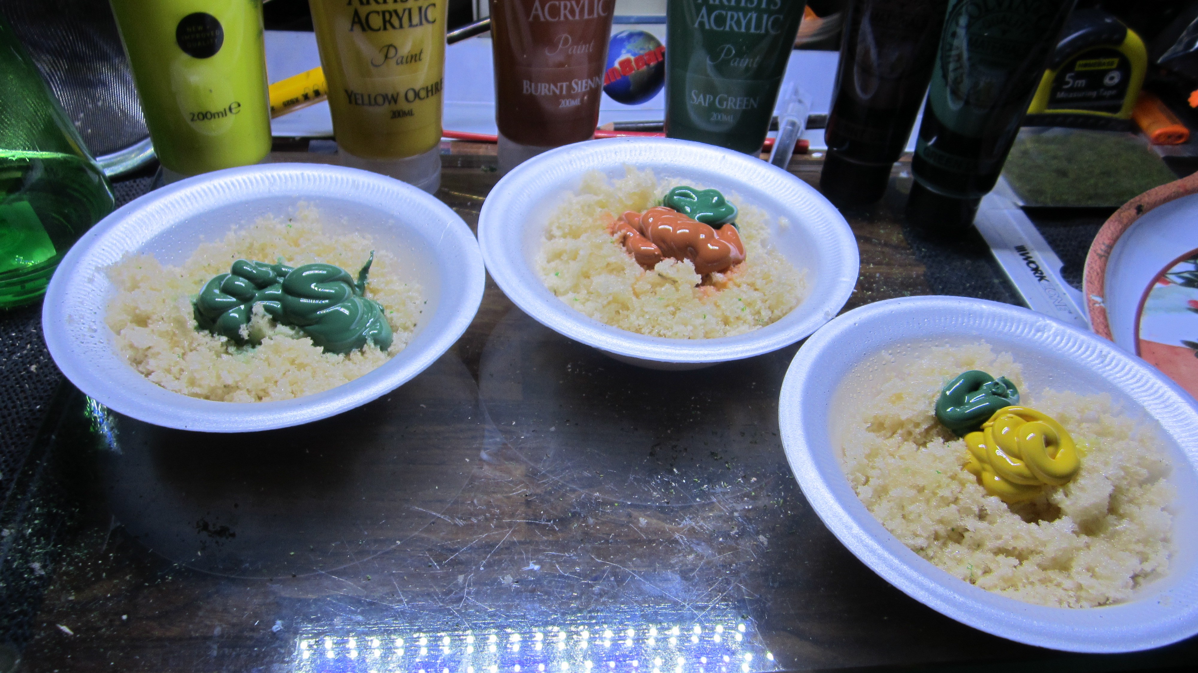
I gathered up the sawdust from the table saw and used acrylic paint to colour it, left it to dry for a couple of days then sieved it into 3 different sizes.
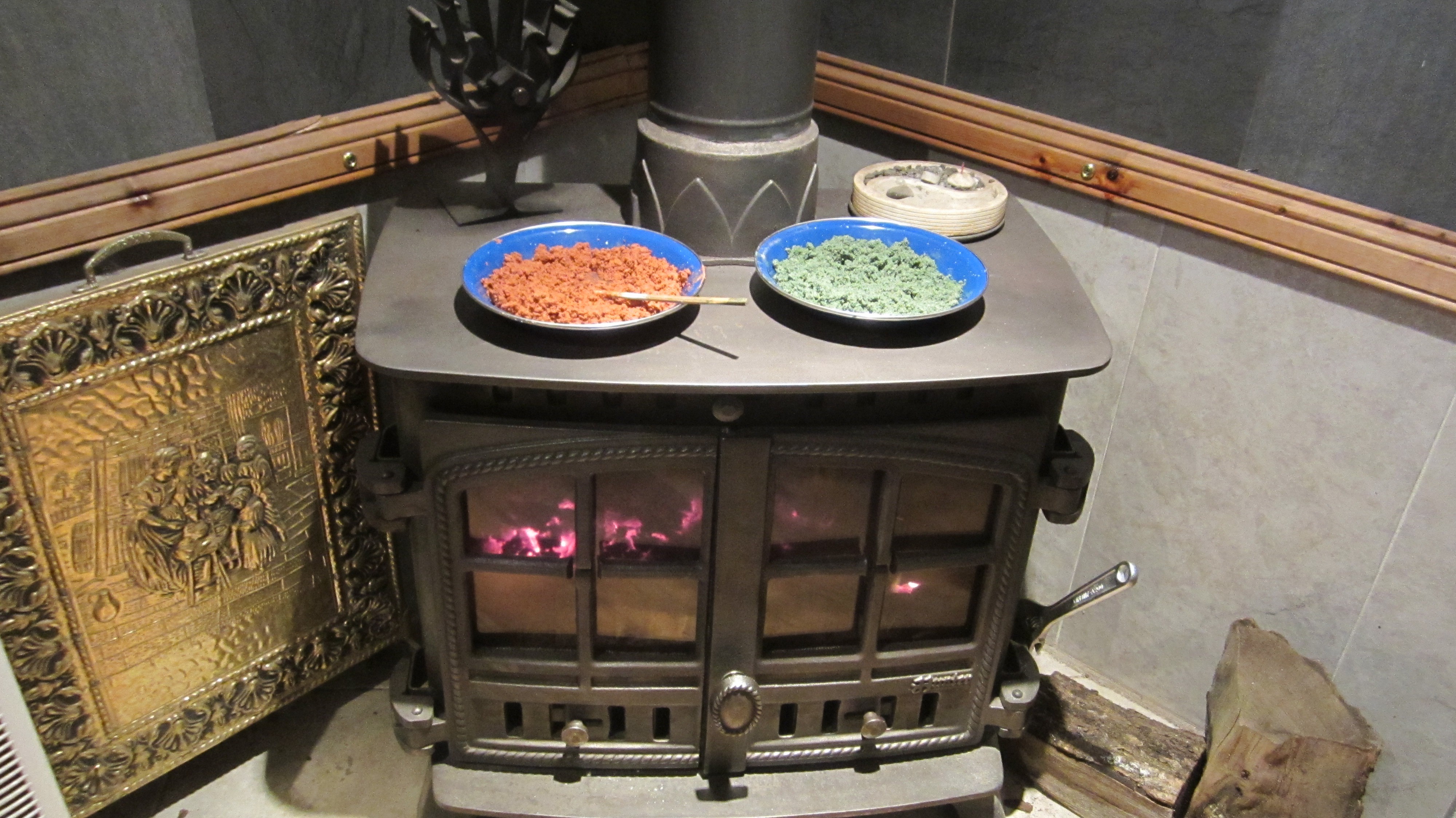
I took some fine light sand out of my aquarium and after mixing it with acrylic paint I aggressively dried it on top of the wood-burner.
I then shredded a sponge with my drill and wire brush and once again coloured with acrylic paint, then air drying for a few days.
Garden earth and leaves collected from the garden baked and sieve graded into 3 sizes completed the terrain material creation.
Blue it!
The grout rock tunnel structure was painted brown then the LED's soldered and sunk into the tunnel roof, later after rigging up a 3v tester from two AA batteries I realised that the LED's were blue, can live with it as it was the only long nose LED's I had, plus they were soldered and embedded in place at this point. These were linked together by the -ve terminal and each with a tail back to the control box area in the tunnel hill centre.
Having being gifted a kitchen table I test fitted the terrain and measured the overall height. I had to cut the corners of the board base to accommodate the leg brackets of the table.
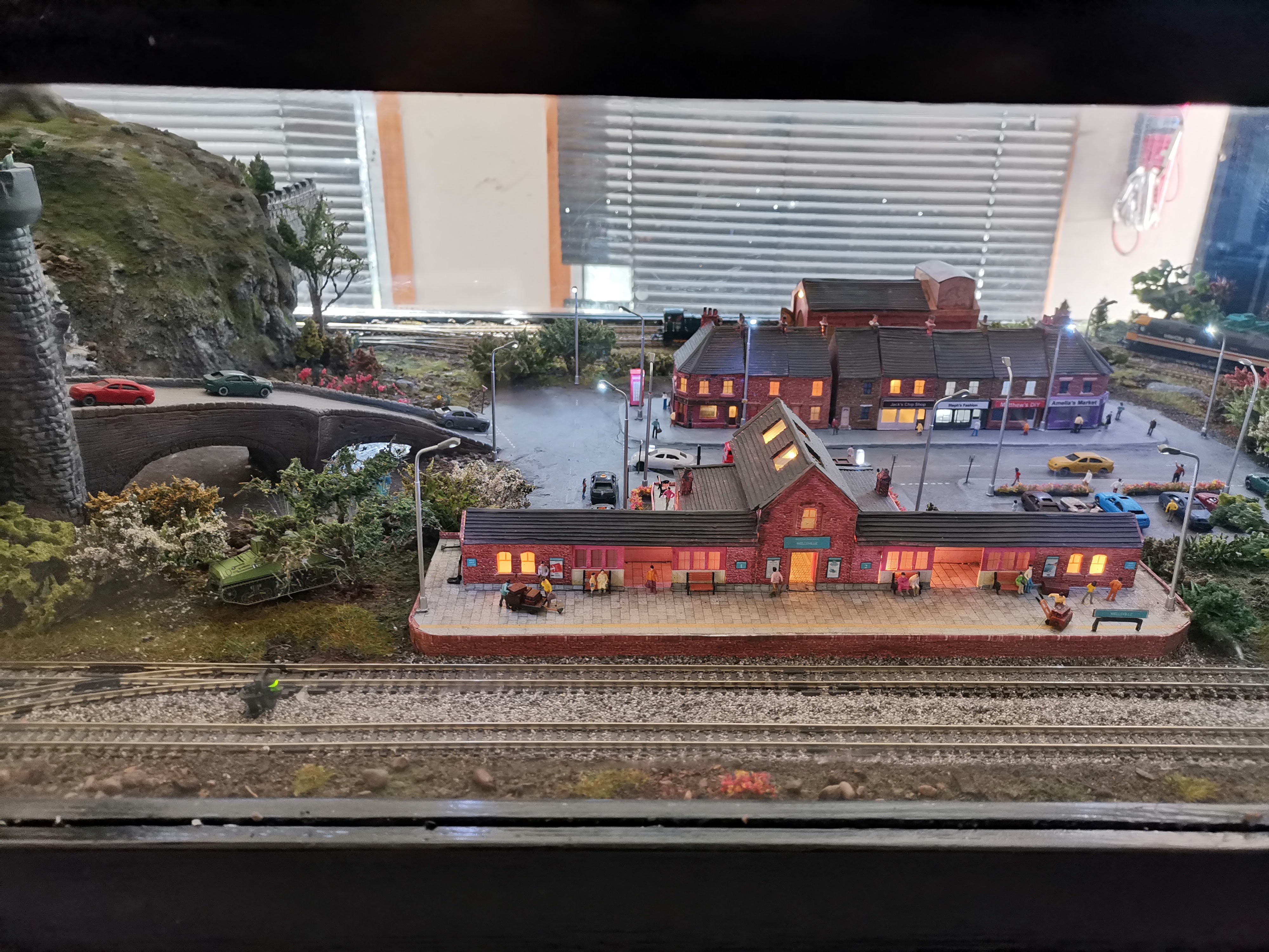
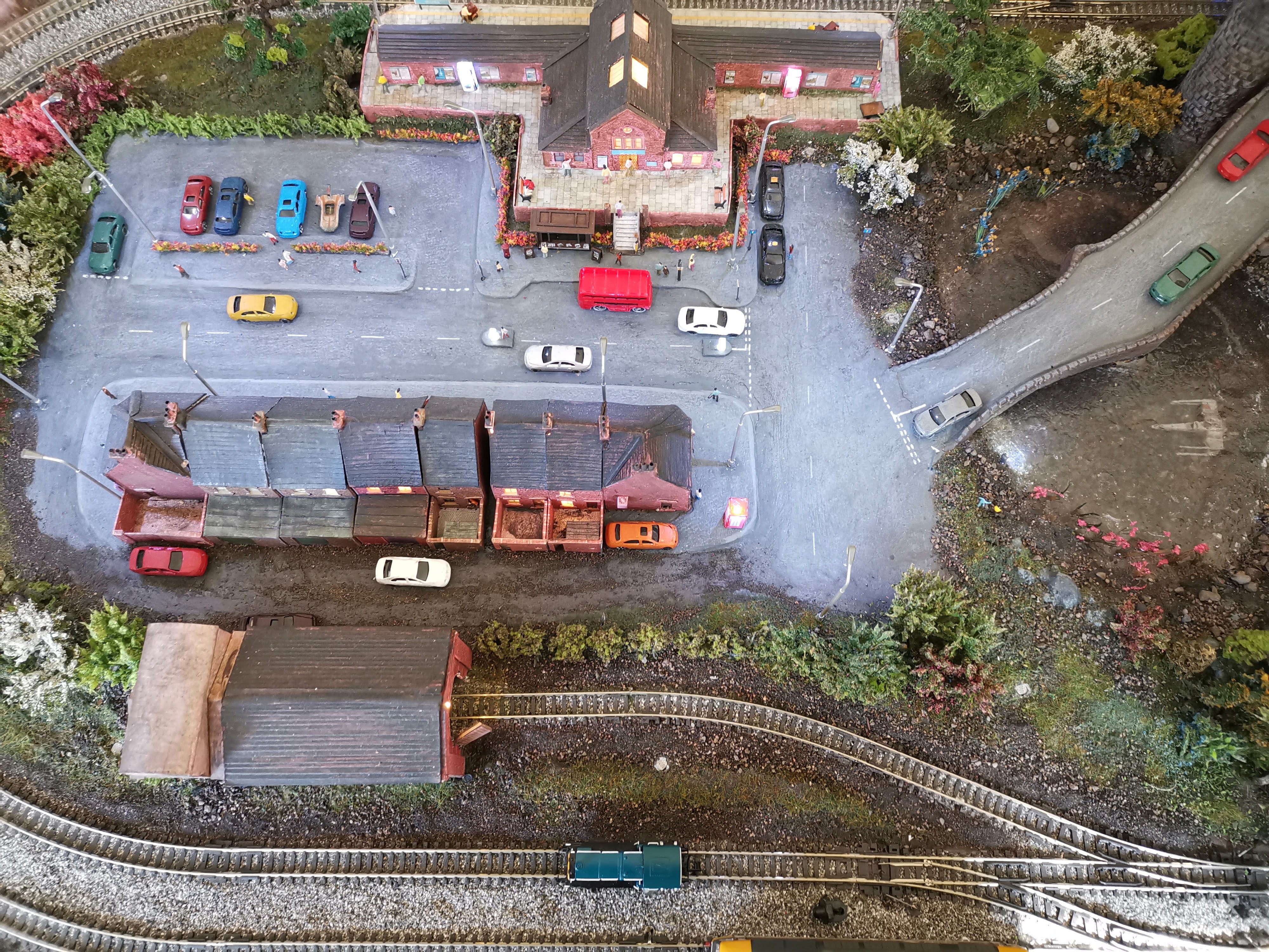
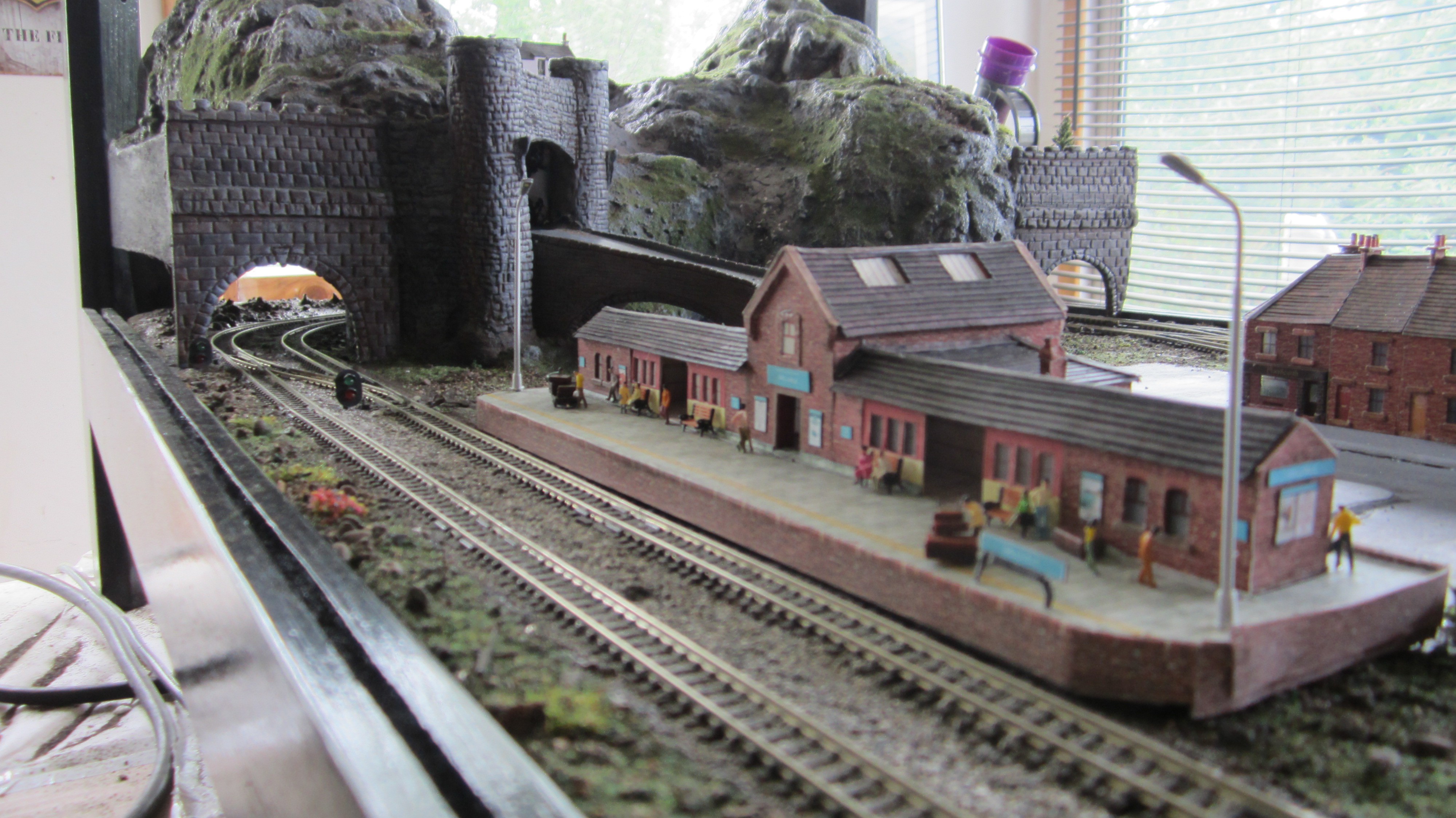
Stairway to Heaven!
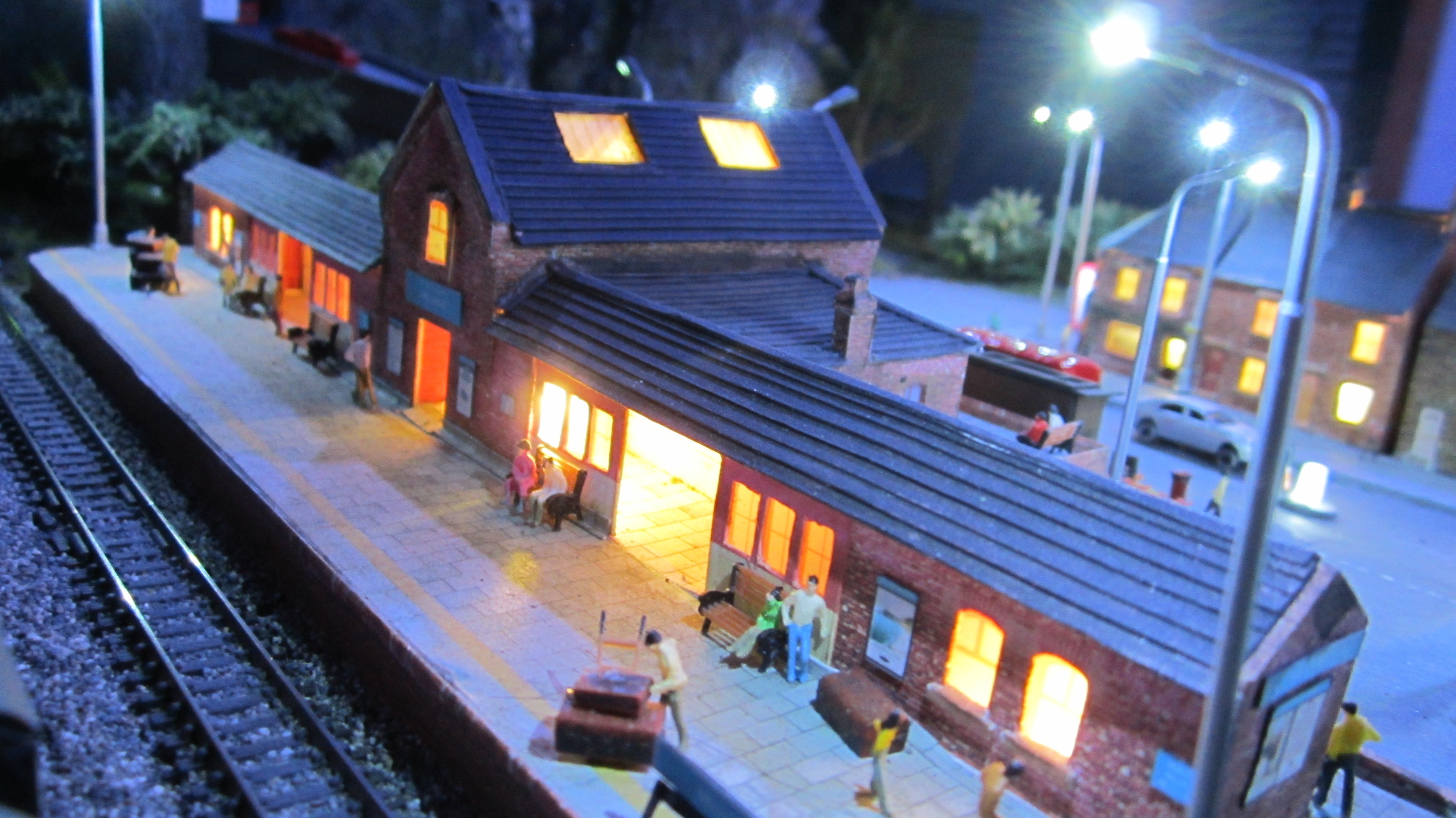
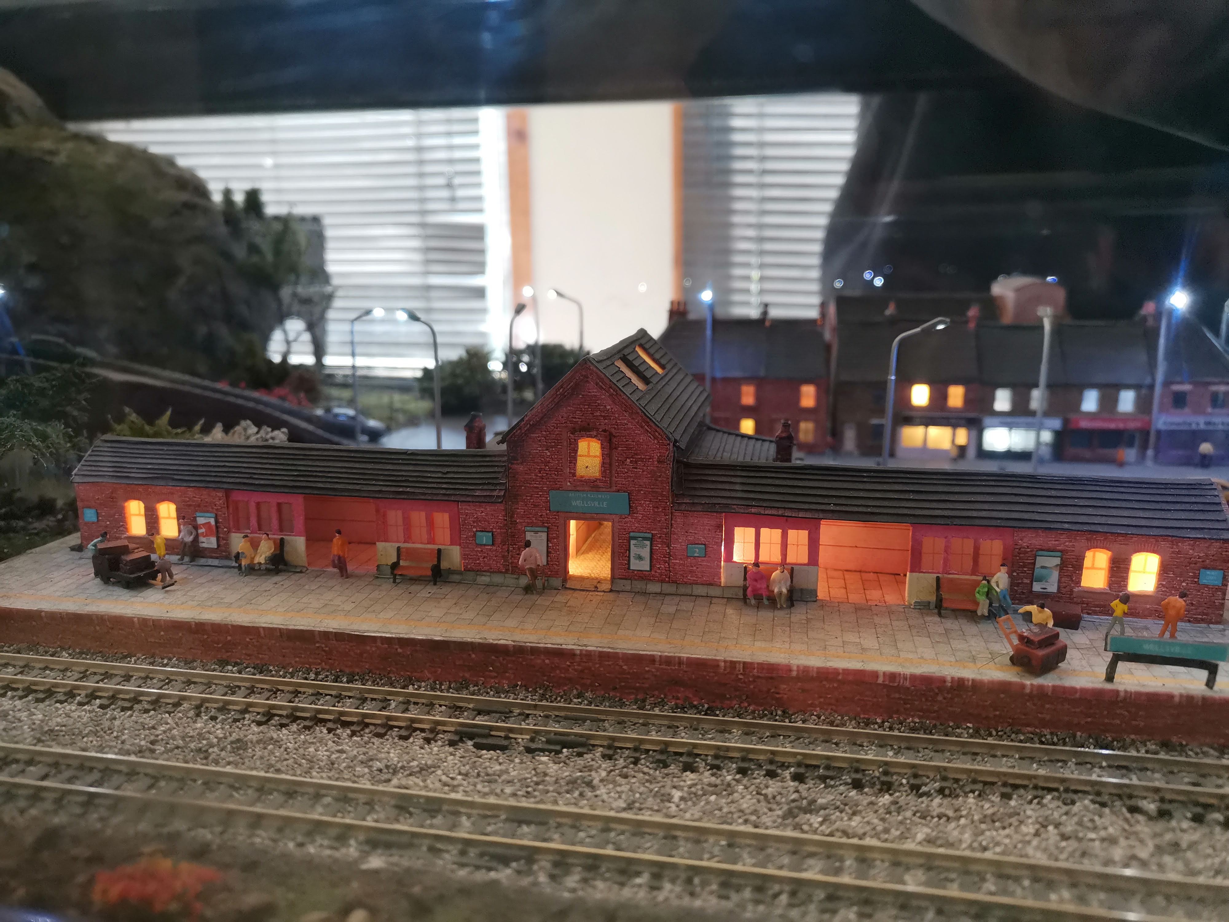
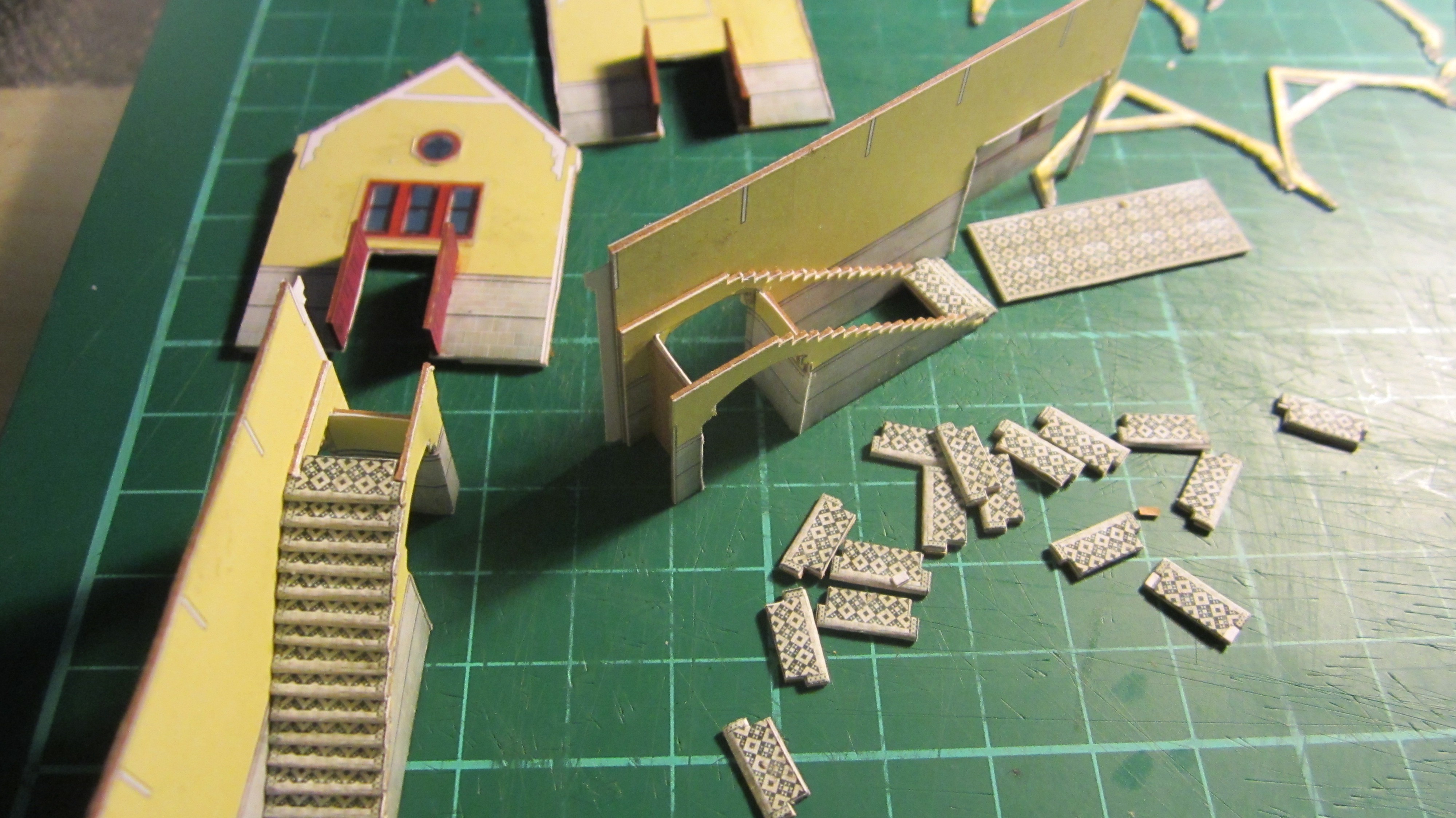
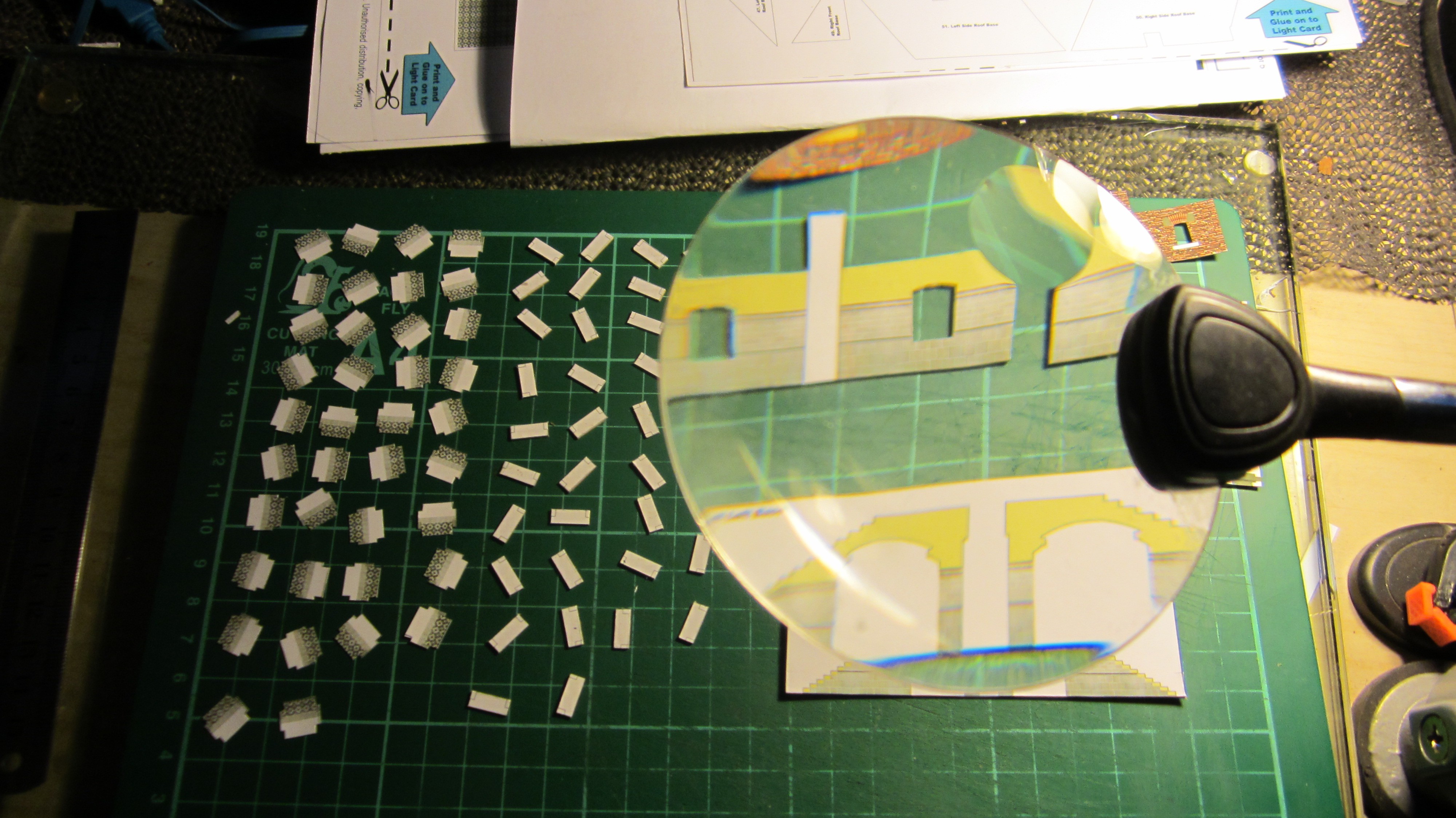
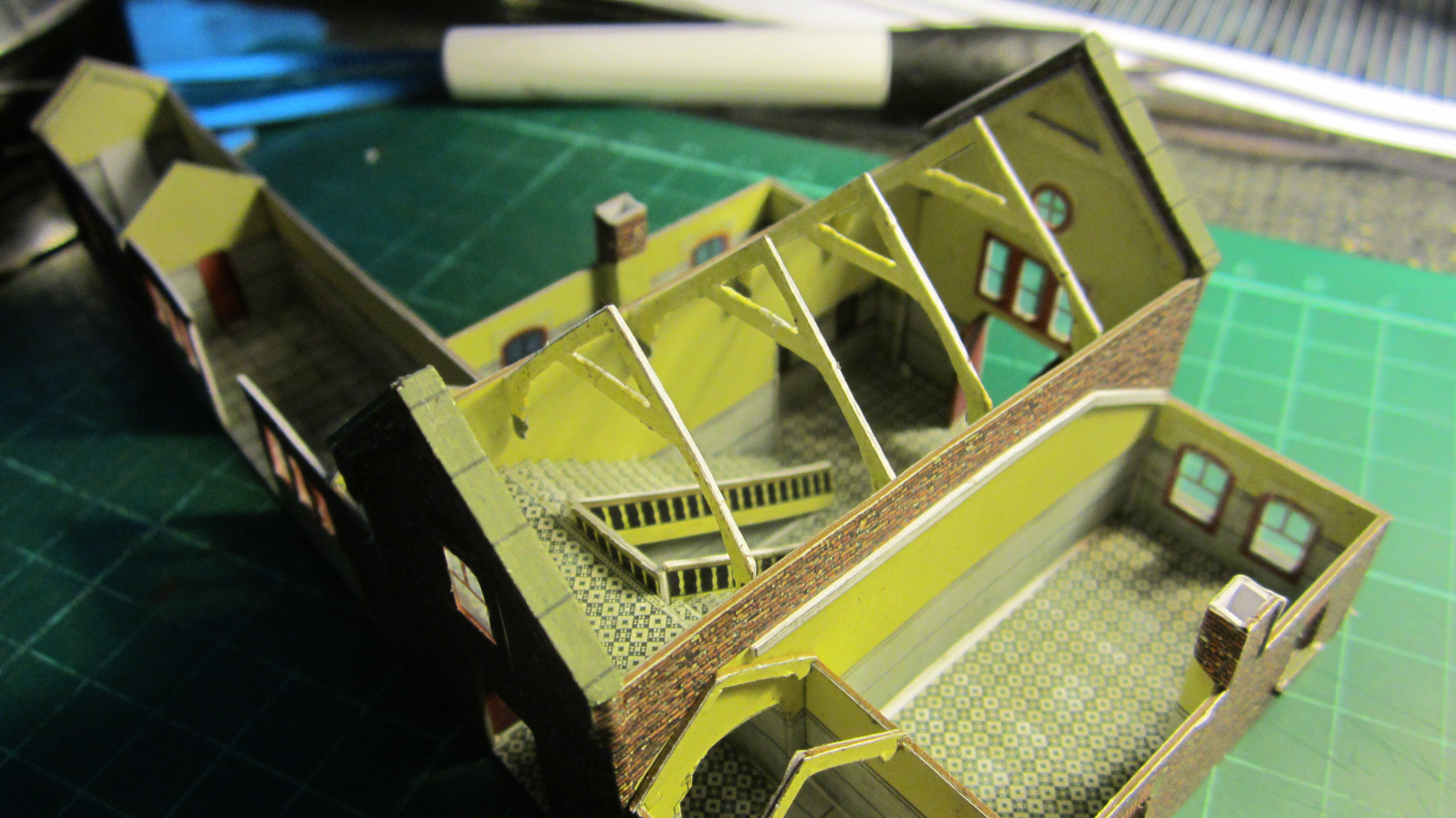
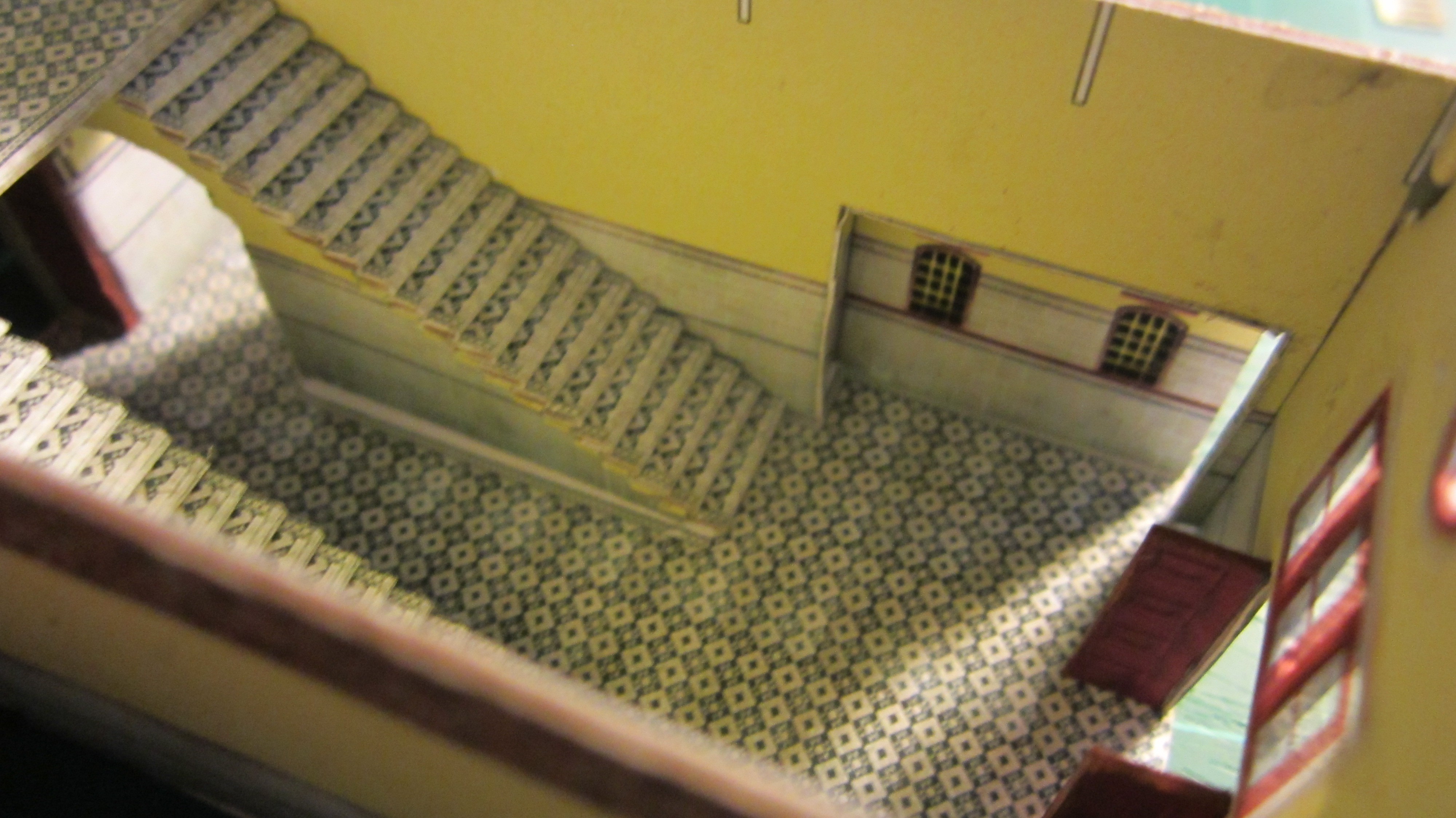
My attention turned to the buildings that we want for the layout, a Station is a must, once again I printed, cut out and assembled the building using scalescene kits. These are pretty detailed and take a lot of time and patience to build, but really satisfying to complete, the stairs and roof trusses on the station look awesome, there is a good chance a casual admirer would not notice, but a nice touch if you take the time to try to see through the windows. More buildings to follow.
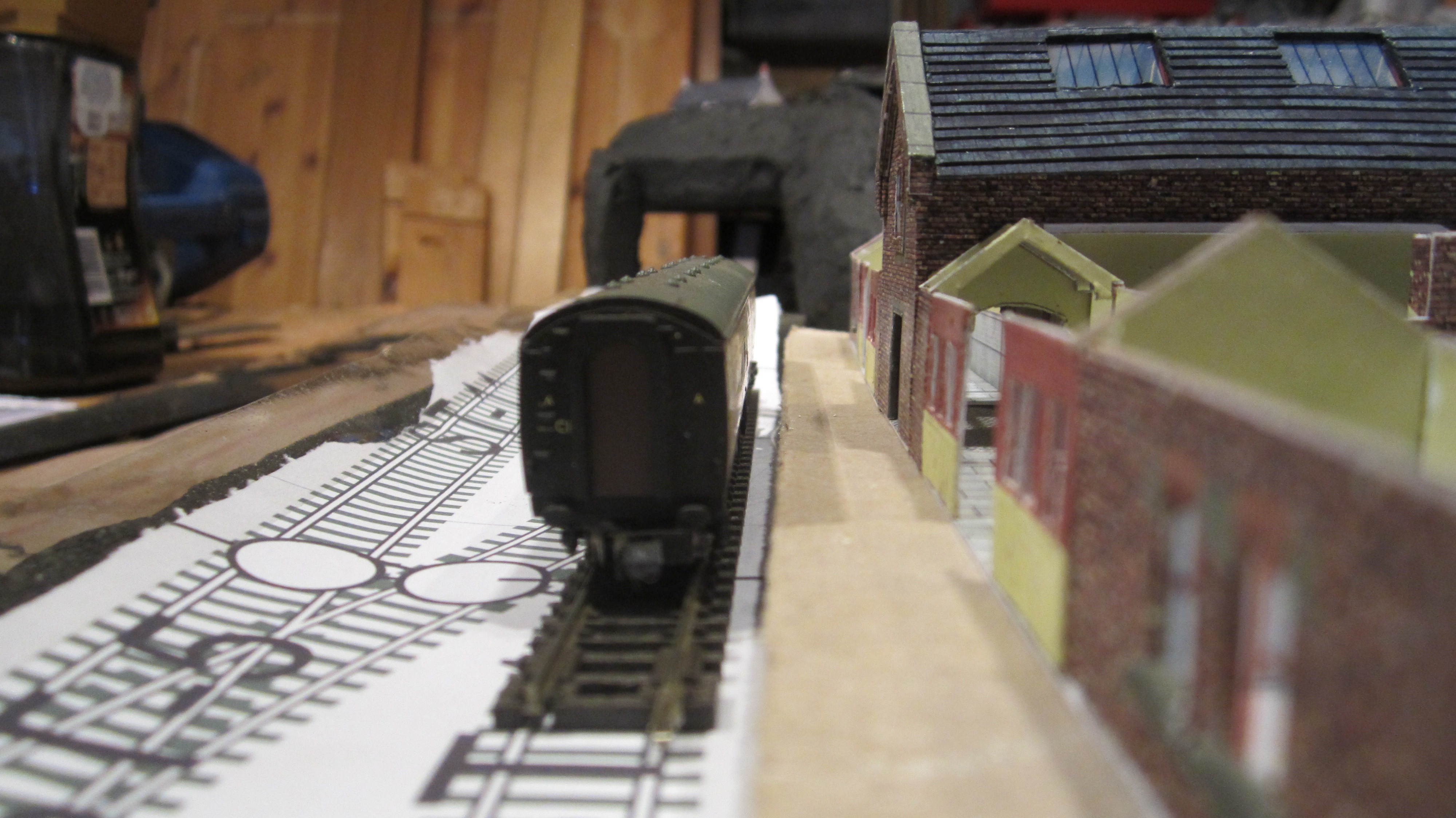
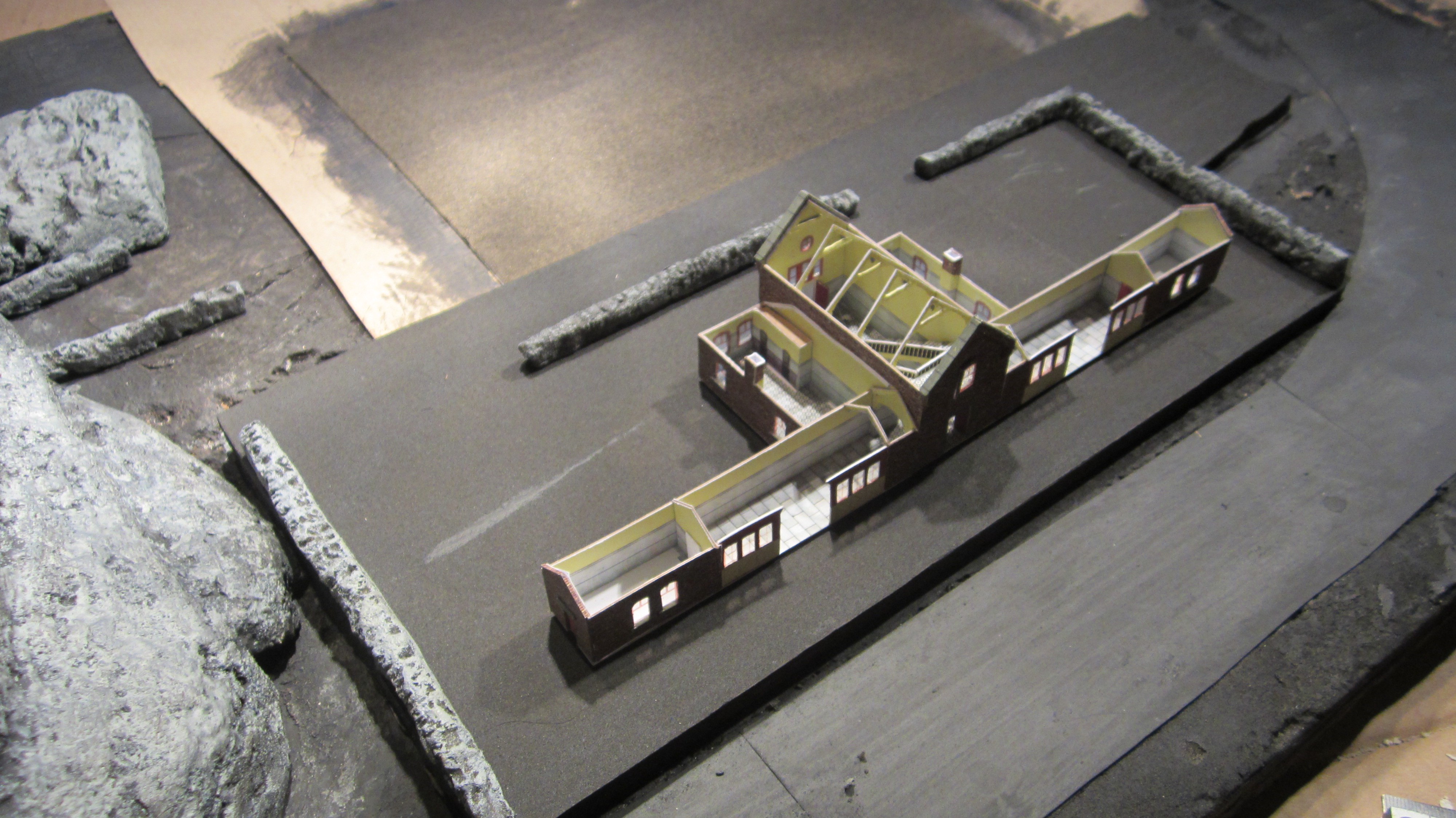
The station was mounted on a bit of plasterboard that happened to be the right thickness for the platform, having finally bought the extra track needed.
The next stage is to run all the wires for LED's, Servo's and track bus back to the control box area ready for fitting the hardware.
Now that the electronics hardware has been confirmed, I've been able to update the code bases to better reflect the hardware we'll use. You can see my code on github
The main changes on the Arduino/Teensy side have been to support the i2c PWM boards, as well as the Neopixel RGB strip. Instead of stripping out and re-writing from scratch I took the classes I had made for the placeholder hardware and added support for the new additional hardware. This means that my local test piece still works but I can easily change the code over to the new hardware once I get it up and running.
On the Django/Webserver side of things I was adding support for the Servos which will be used to control the track point switching. The buttons have been added and I've included an image of the track layout to make it clearer what areas the servos affect. I'd like to add a further layer to the interface that indicates what position the track switch points are in and how the servos effect this. It's a work in progress.
Further backend work was also done so now the Django database is updated when commands are sent to the Arduino Effects Manager. This means when we refresh the page it should show the current positon of all of the connected hardware. A future development will be to add feedback from the Arduino Effects Manager so that the database is fully reflective of the hardware. Currently we're working on the assumption that the database and physical hardware currently match up which might not be the case at first start.
The project has been quiet on Hackaday but we've been working away on finalising the electronic elements. We've been working to build the layout, settle on the scenery and, most importantly for electronics, settling on the number of LEDs required. We're estimating around 60 single LEDs across the whole table for lighting effects. This includes Street Lighting, Cars and individual LEDs inside the housing. Once that was settled, I went shopping;
17th of December is our wiring date. It's the day I'll be onsite with the build and we'll be putting all of the electronics together. The planning stages have been fun but I can't wait to get hands on.
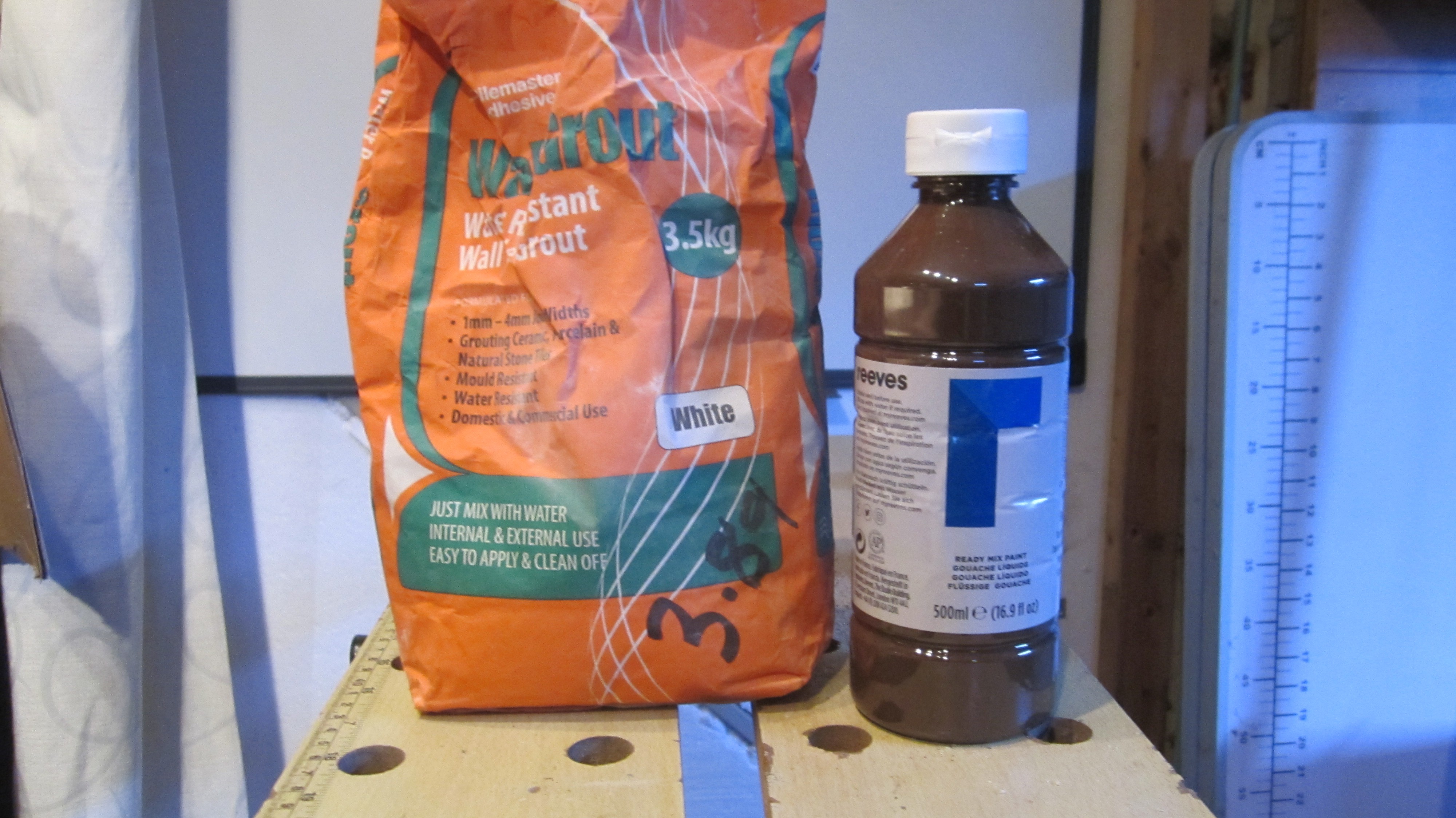
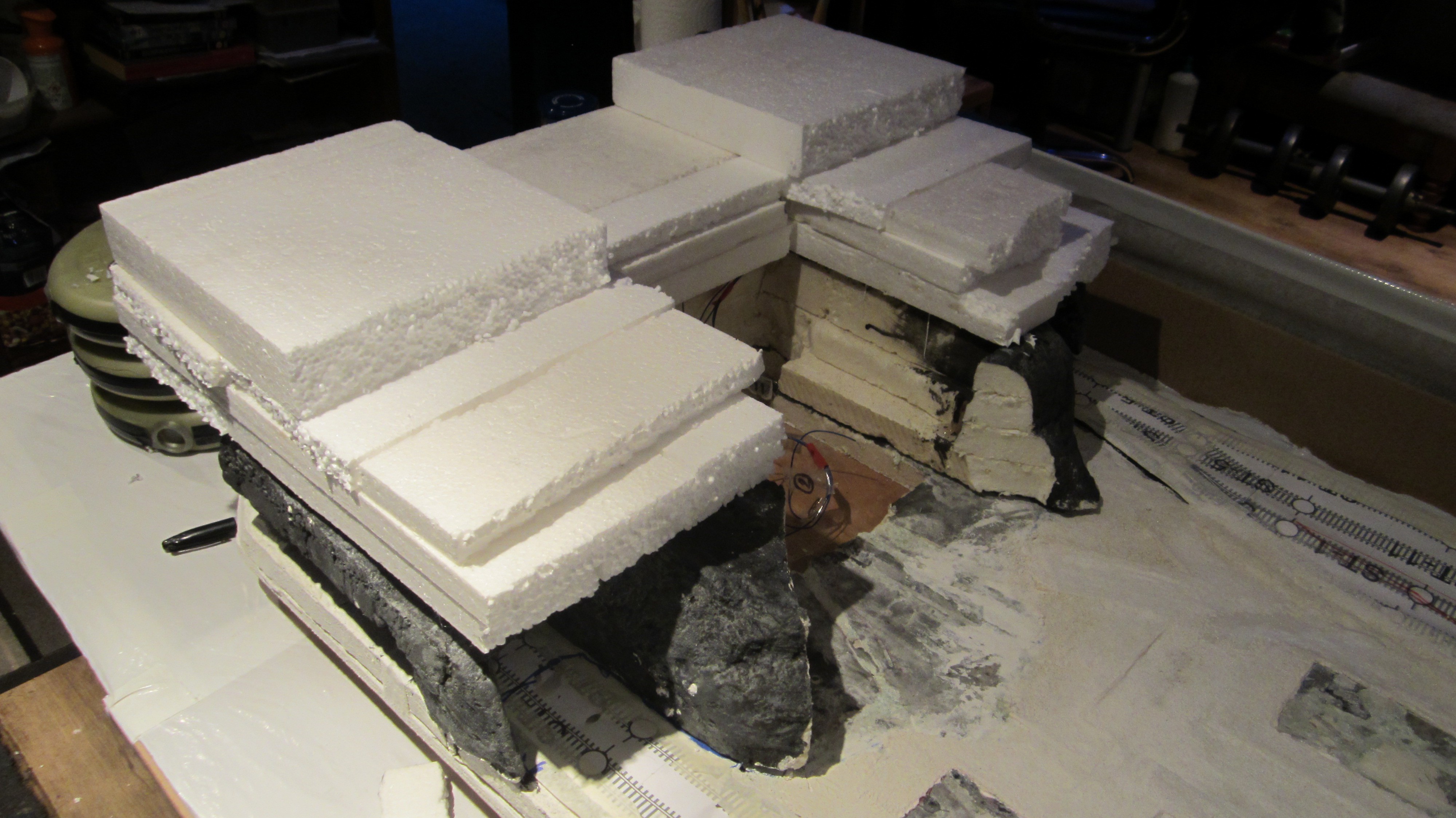
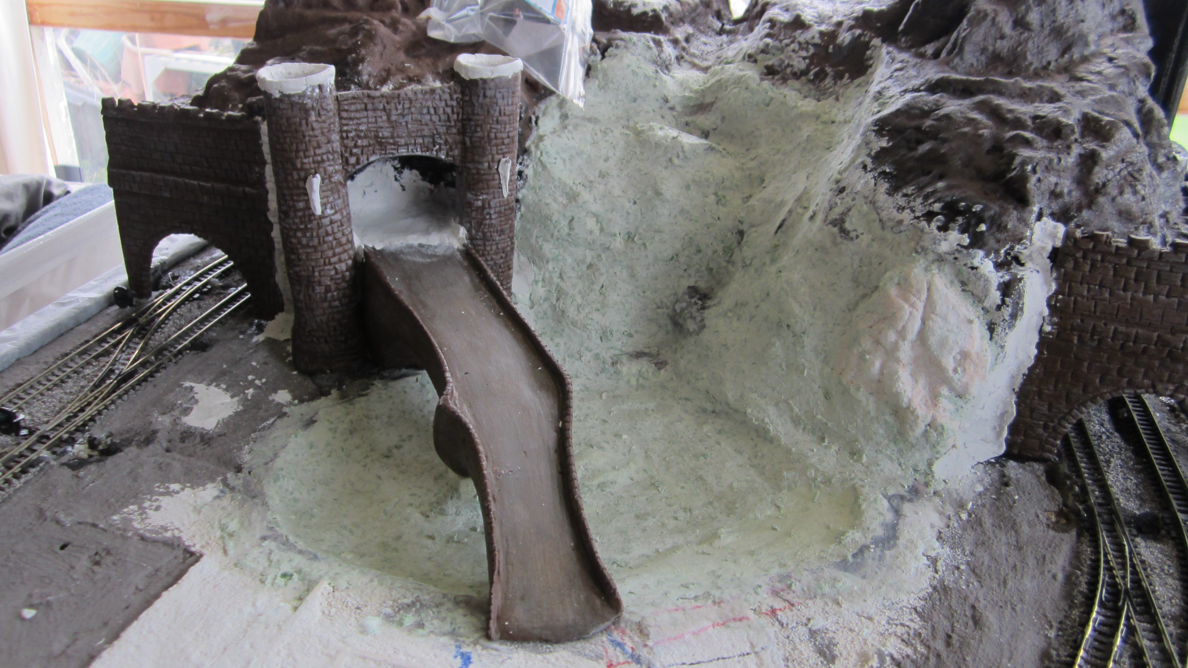
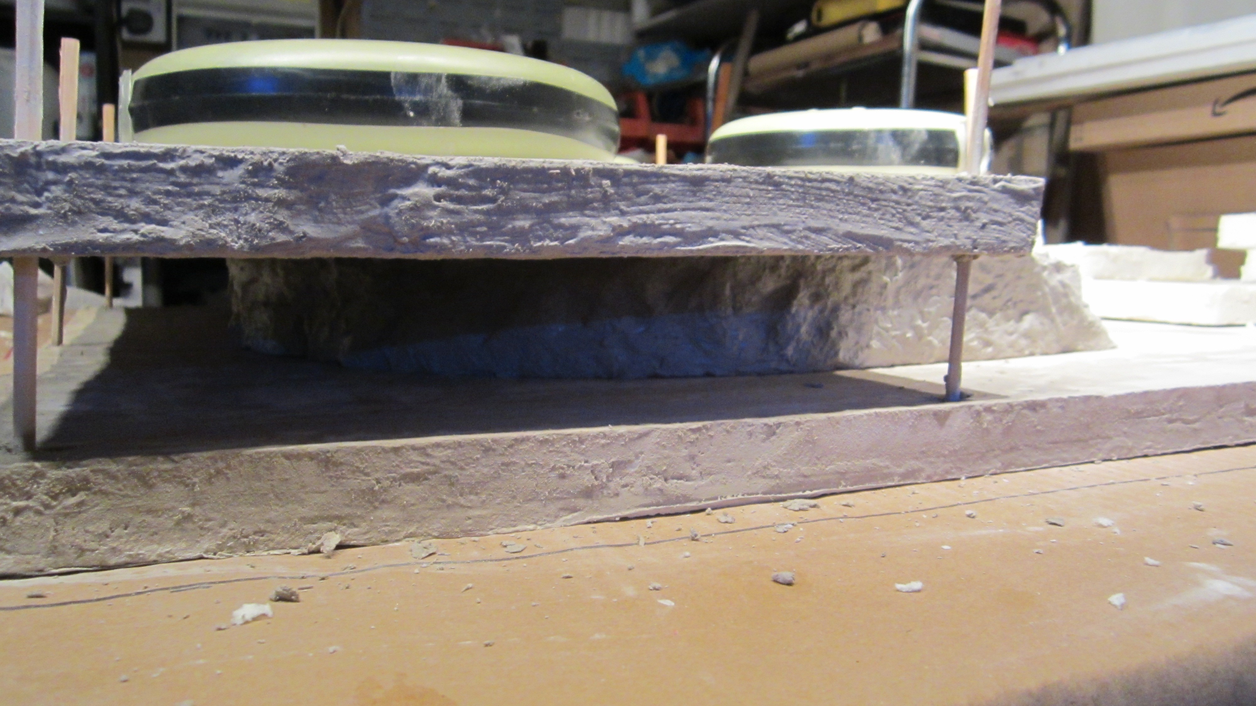
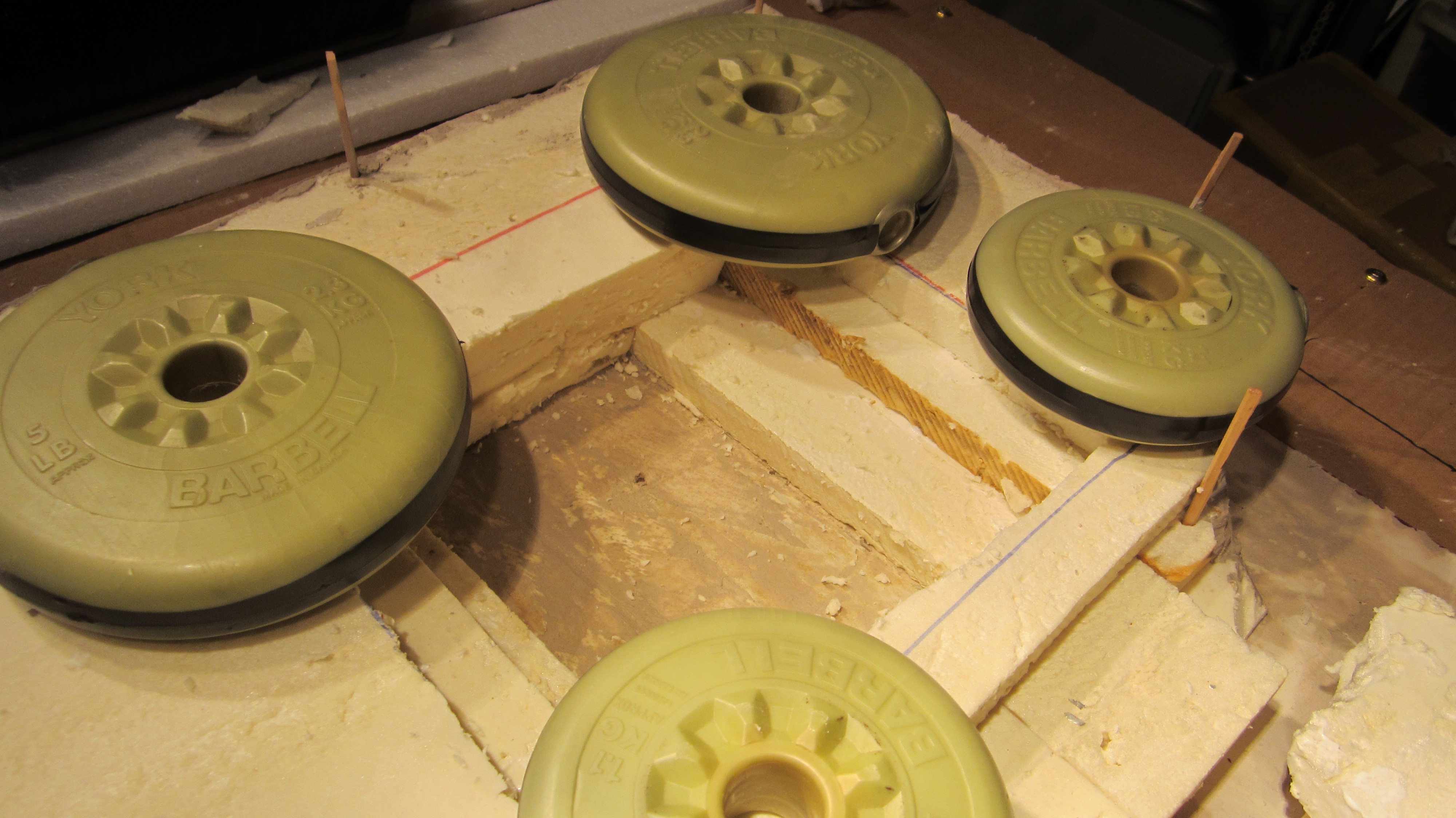
Having recently tiled the bathroom I had some grout left over, it occurred to me while tiling that this could be used to make scenery for the train table. I sourced some cut offs of wall insulation foam by chance at my local tile DIY shop - shout out to Solway Tile, cost me £1.00 for insulation and £3.89 for the grout, 70% used on the bathroom the rest used for project.
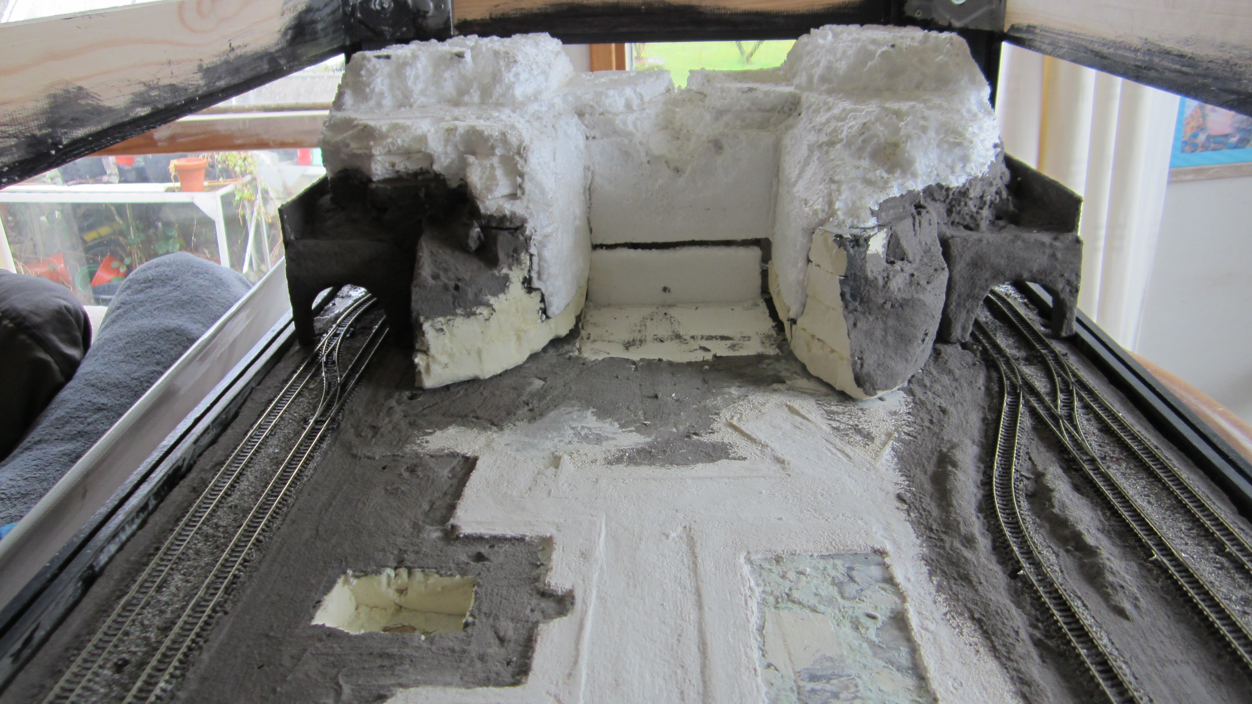
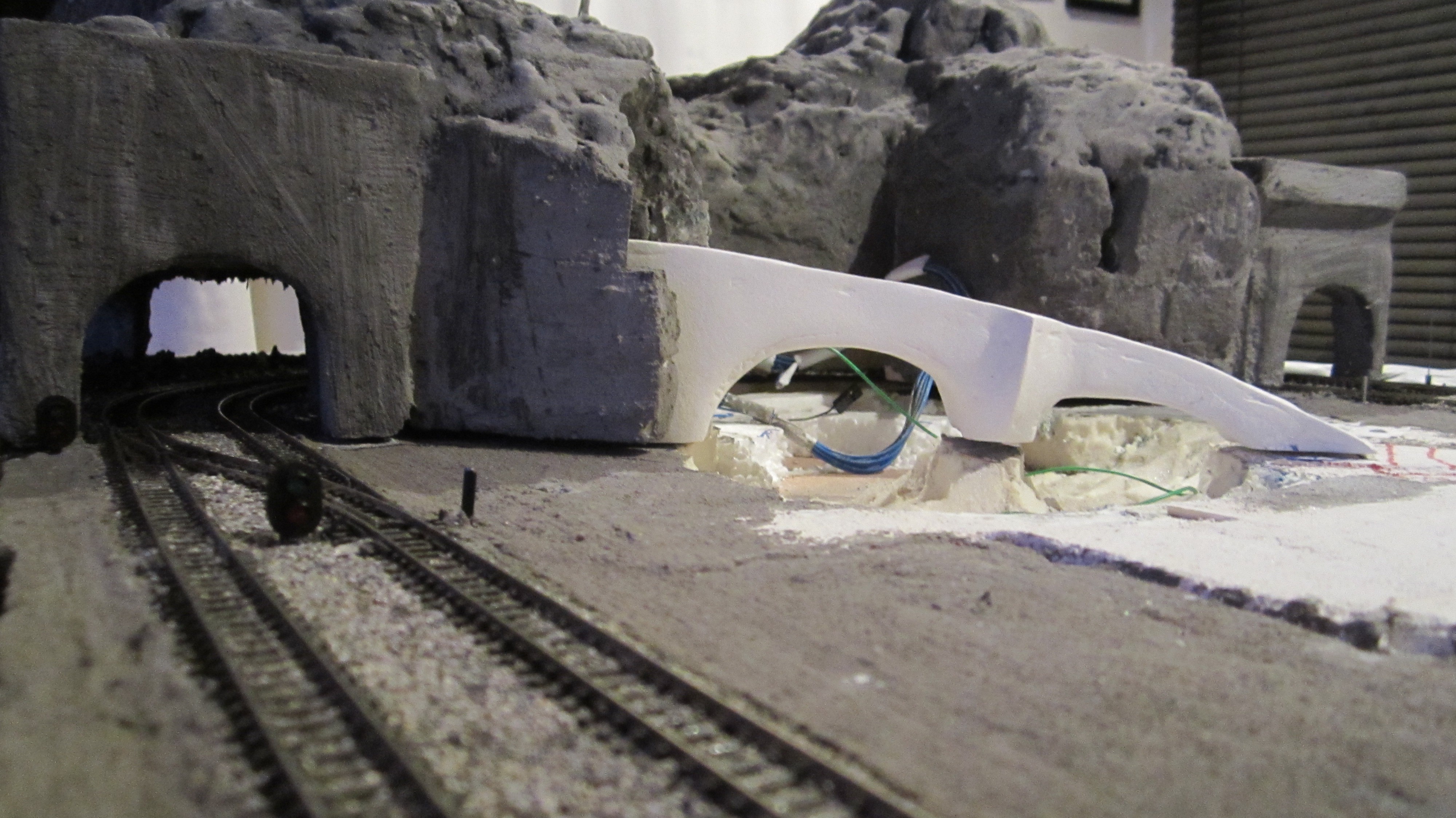
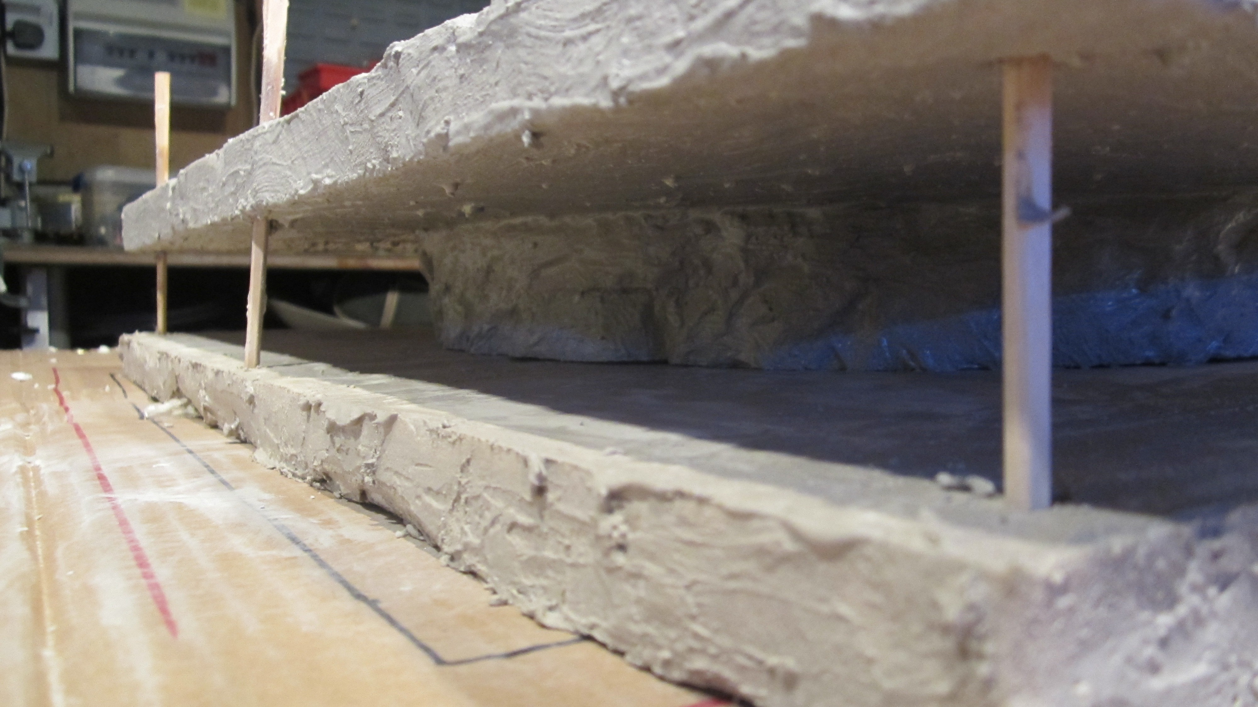
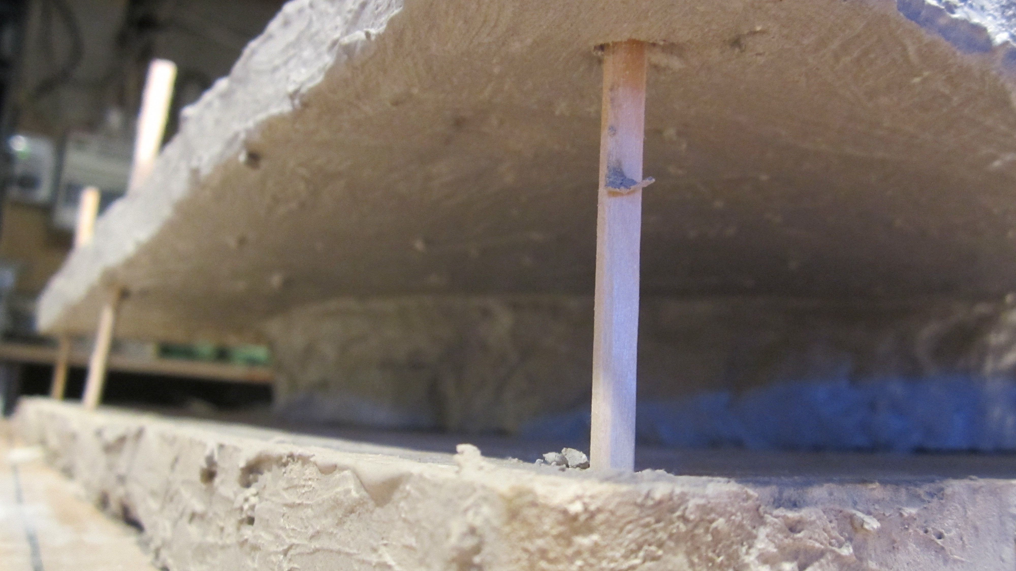
We wanted a tunnel with lighting options and with the sides being visible via the perspex sides, using the foam and a knife I measured up the curve of the track from the full scale plan and cut the foam roughly to the right shape, I then carved the foam with the knife, cutting out chunks to look like rock face.
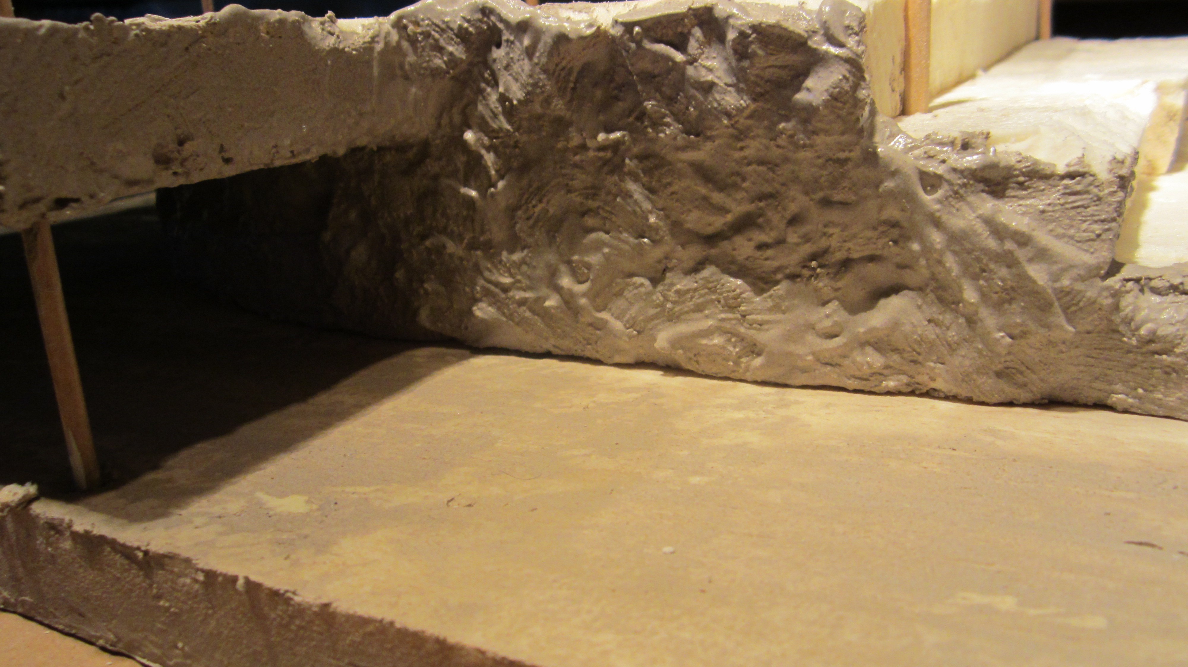
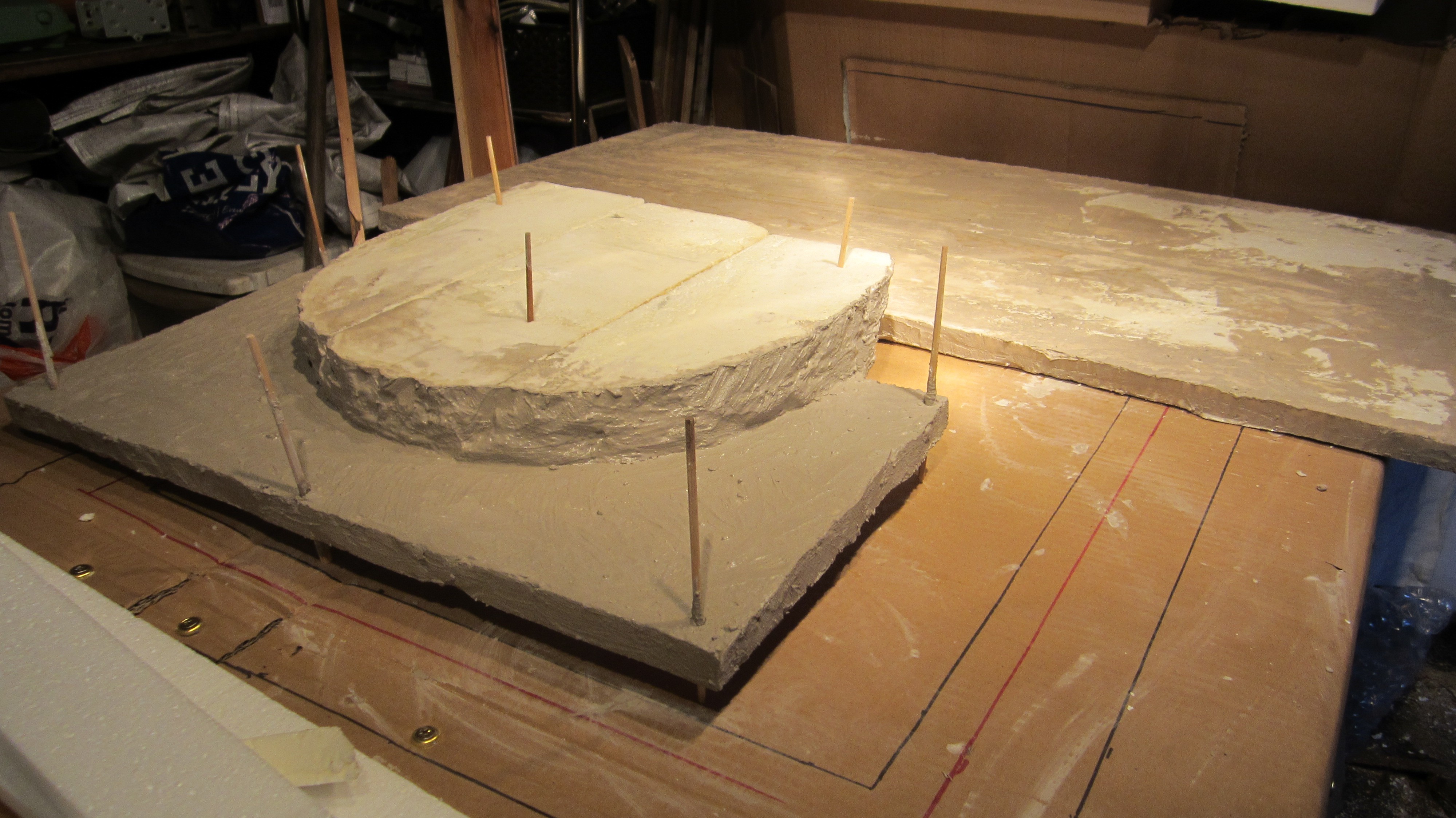
I constructed the tunnel by joining the pieces of insulation together with cocktail sticks and wood glue, I used chop sticks to keep the foam in line with the base. I then mixed up the grout and added some brown paint (£1.99 The Range) just to take the whiteness off. I painted the grout on to the foam with an old brush and assembled the tunnel structure. The chop sticks allow me to leave the upper section free to remove for further construction.
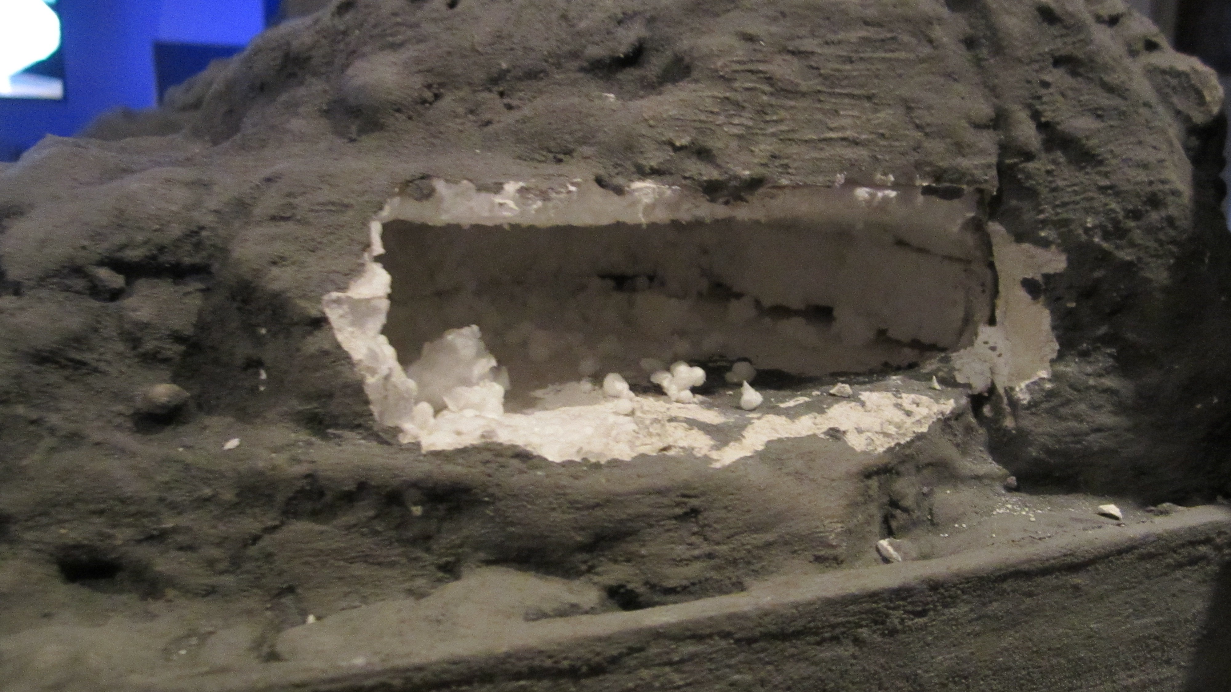
As the grout was drying I realised that the centre section of the hill that forms the tunnel would be a great place to hide some electronics and if I can make it accessible from the top somehow, it would be ideal for top down maintenance or expansion.
Kind of winging it at this stage with the terrain, adapting as we push forward with the build, the rough terrain idea is for a rolling Hill with tunnels in half the layout and which levels out to a small village with a station and engine shed. We really need an idea of electronics requirements at this point (position and number of LED's, points servos, signalling and sensors) , both for the electronics design and the modelling .
Outstanding work.... I'd love to complete this project. I'm researching how to set up a DCC train set with scenery etc... I graduated as an electronic engineer many moons ago and a lot of the info and skills have long since deserted me. Well done.... following and taking a keen interest. Inspiring.

Lovely work. Just one thing, I2c with lower case 'c' goes just too for! "I2C" comes from acronym IIC (Inter-Integrated Circuit) which is written 'I squared C' and typed with the 2 as a superscript. Practically no one has superscripts in comments for C code and they write it I2C. No lower case! It leads to acronym rot, then, shudder, pronouncing as a word!
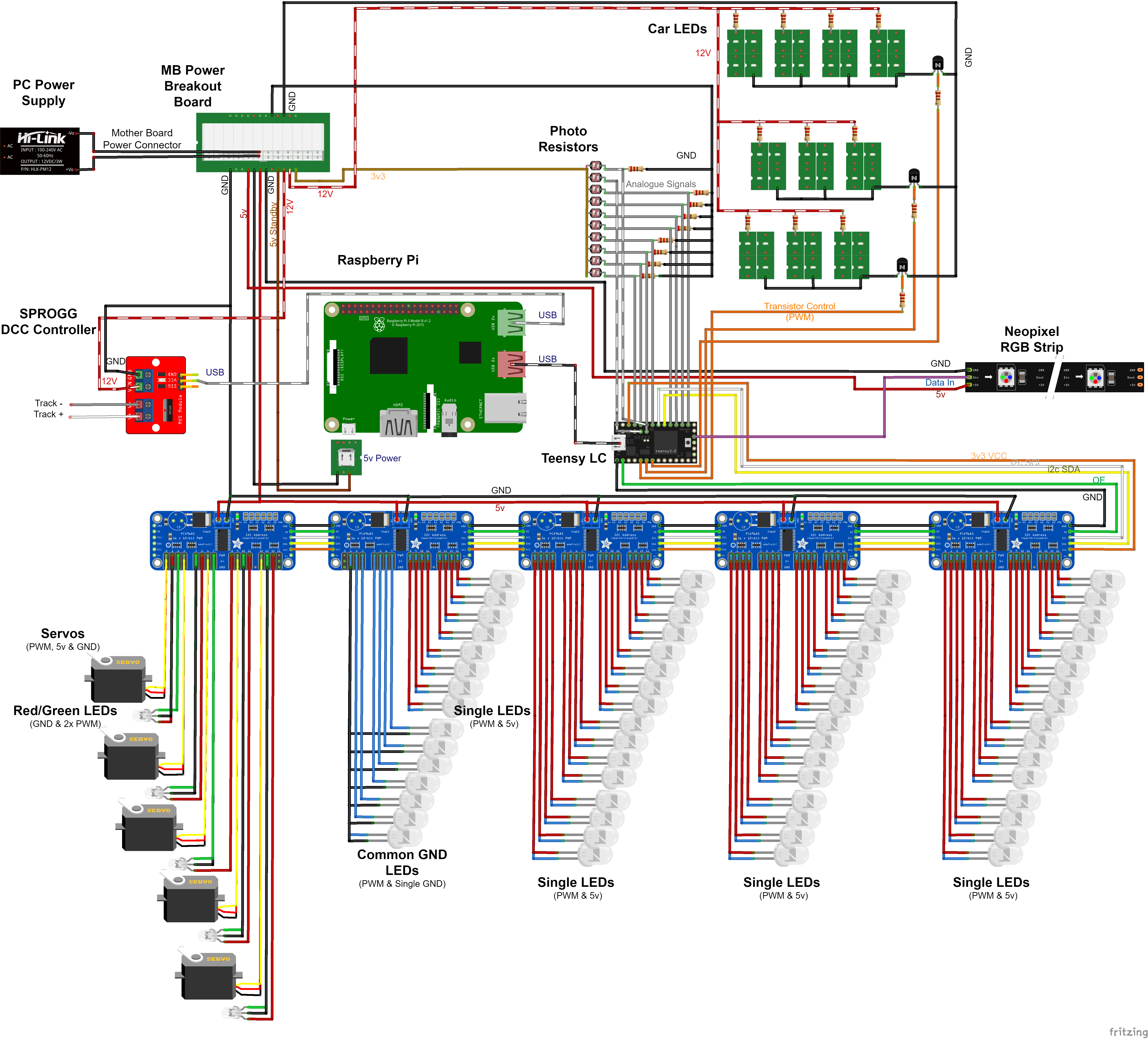


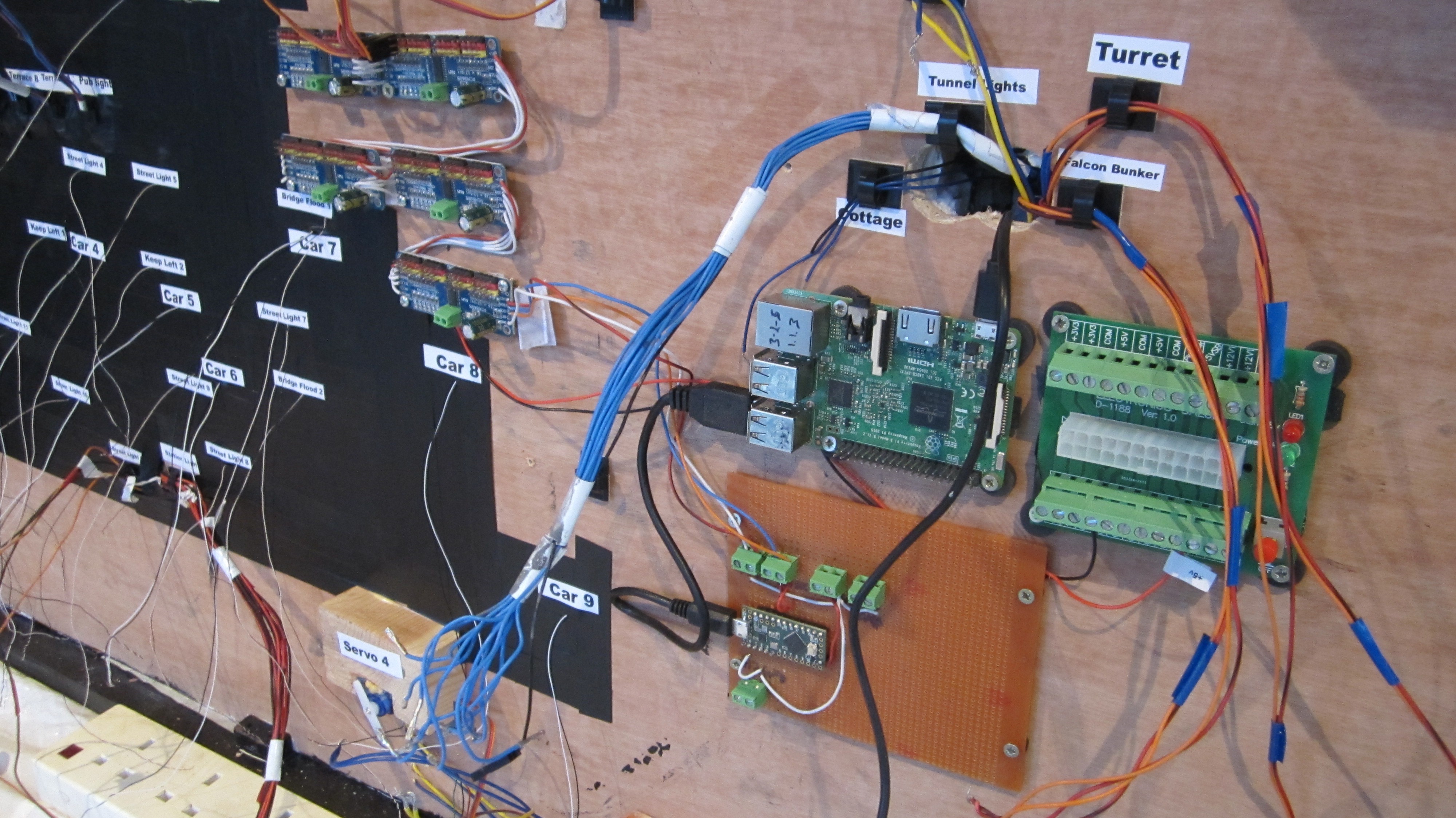


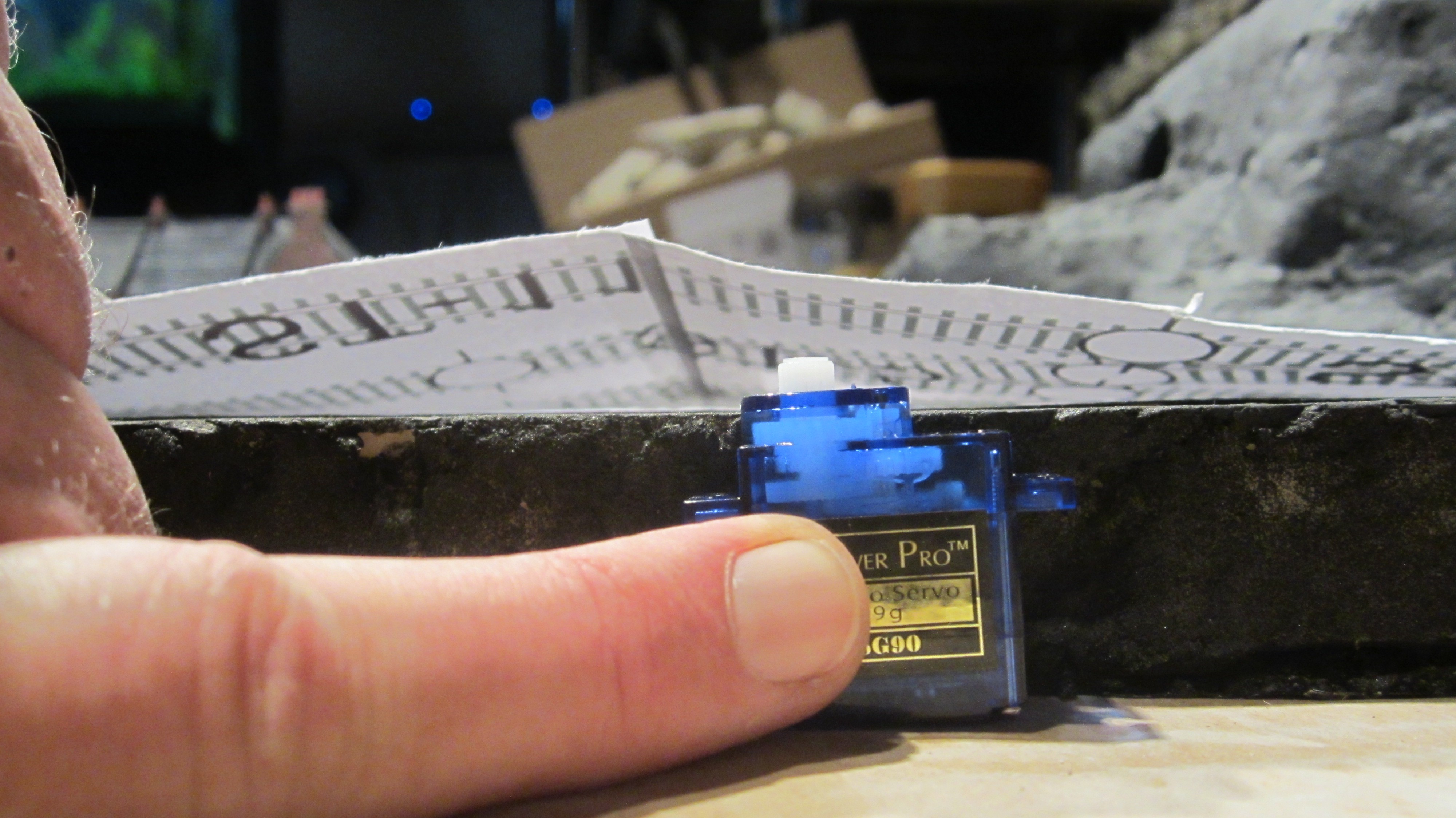
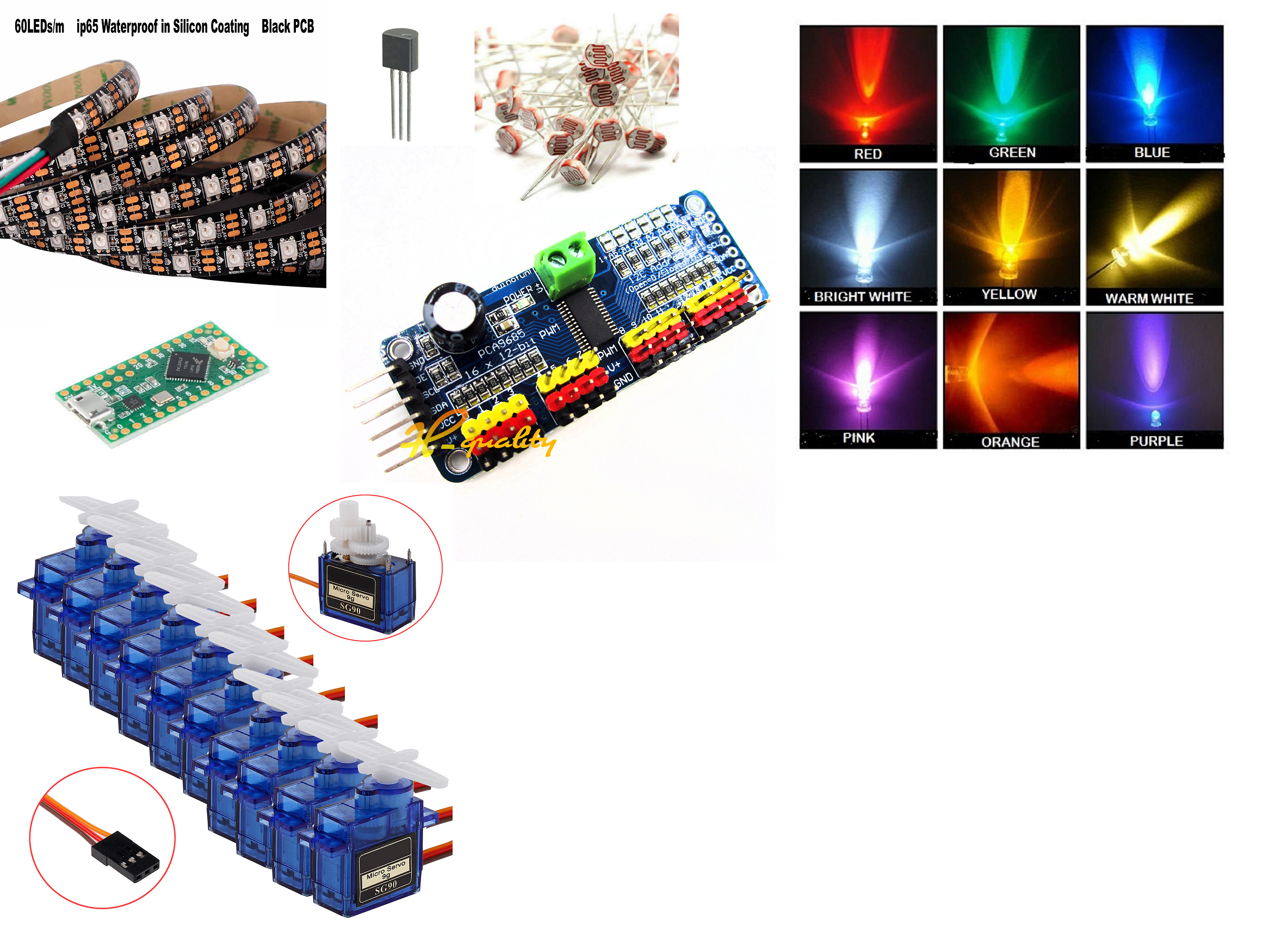 The strip lighting LEDs will be used around the rim of the top of the table. This will give us ambient lighting that can be controlled via the web interface. At a later date we'll be able to add cool effects and automation such as day and night cycles, moon and sun cycles, and maybe some SciFi effects for fun. The rest of the LEDs will be inside the buildings for nighttime effects. The servos will give us control of the track allowing the trains to move onto different parts of the layout. LDRs will be used for lighting automation and the transistors are needed for controlling some of the higher voltage LED strings. Finally we have the Teensy LC for low level control and a nice I2C PWM board with 16 channels that can be used for providing the Servo and Single LEDs with power and PWM control. These boards seem really nice because we can reduce our pin requirements from over 60 devices to just a single 2 pin I2C bus. Each board can support 16 devices (LEDs and Sevos) and we can daisy chain up to 62 boards together. Thankfully we only require about 5...
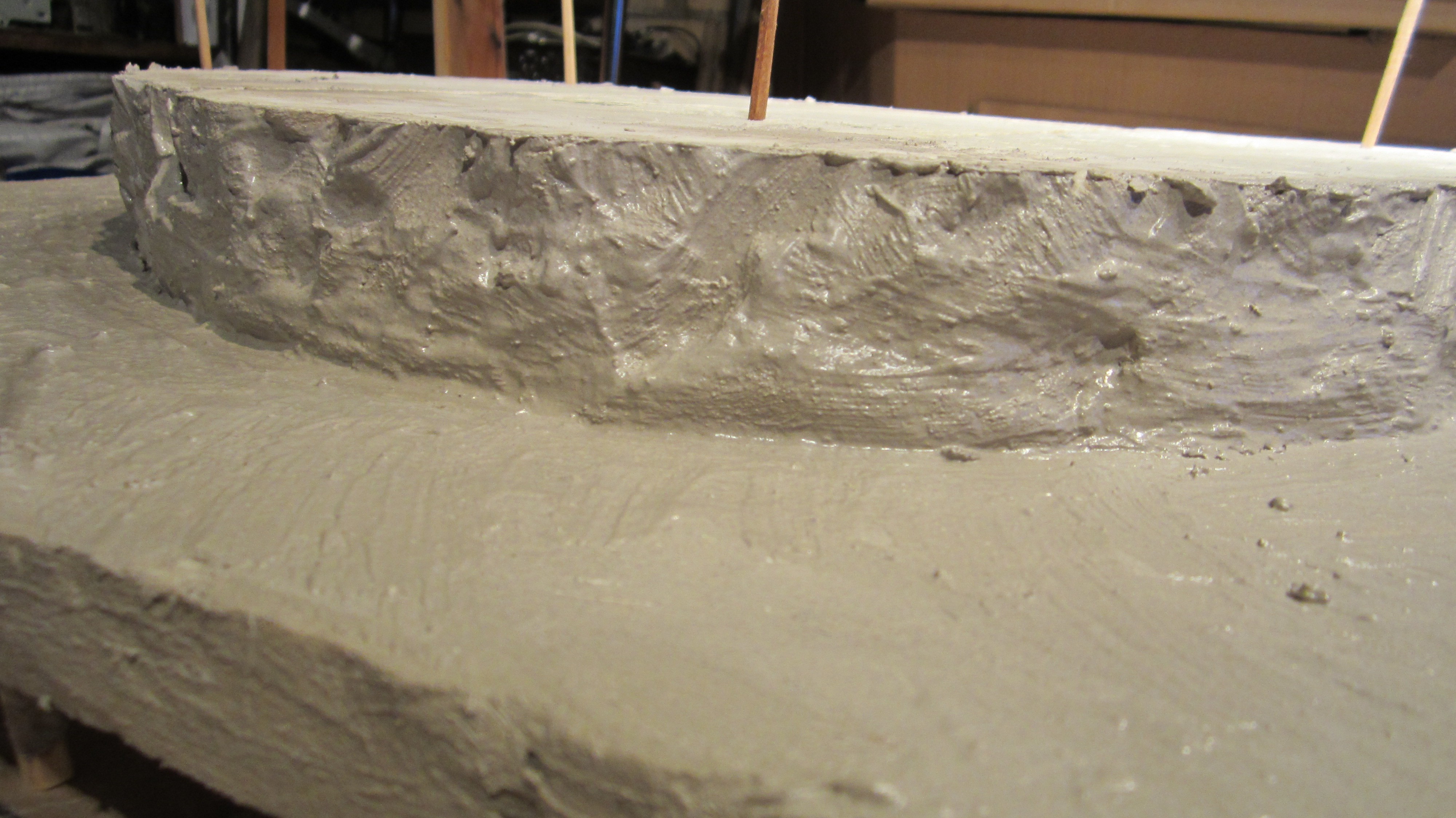
 TM
TM
 scubabear
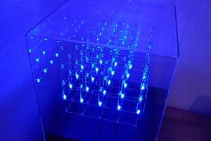

 Idrees Hassan
Amazing and inspiring work :-) I'm working on a microcontroller driven DC controller for animating exhibition and display layouts myself.