 jaromir.sukuba
I thought of instrument like this for a long time, now when HaD prize has musical challenge section, I decided to materialize my ideas.
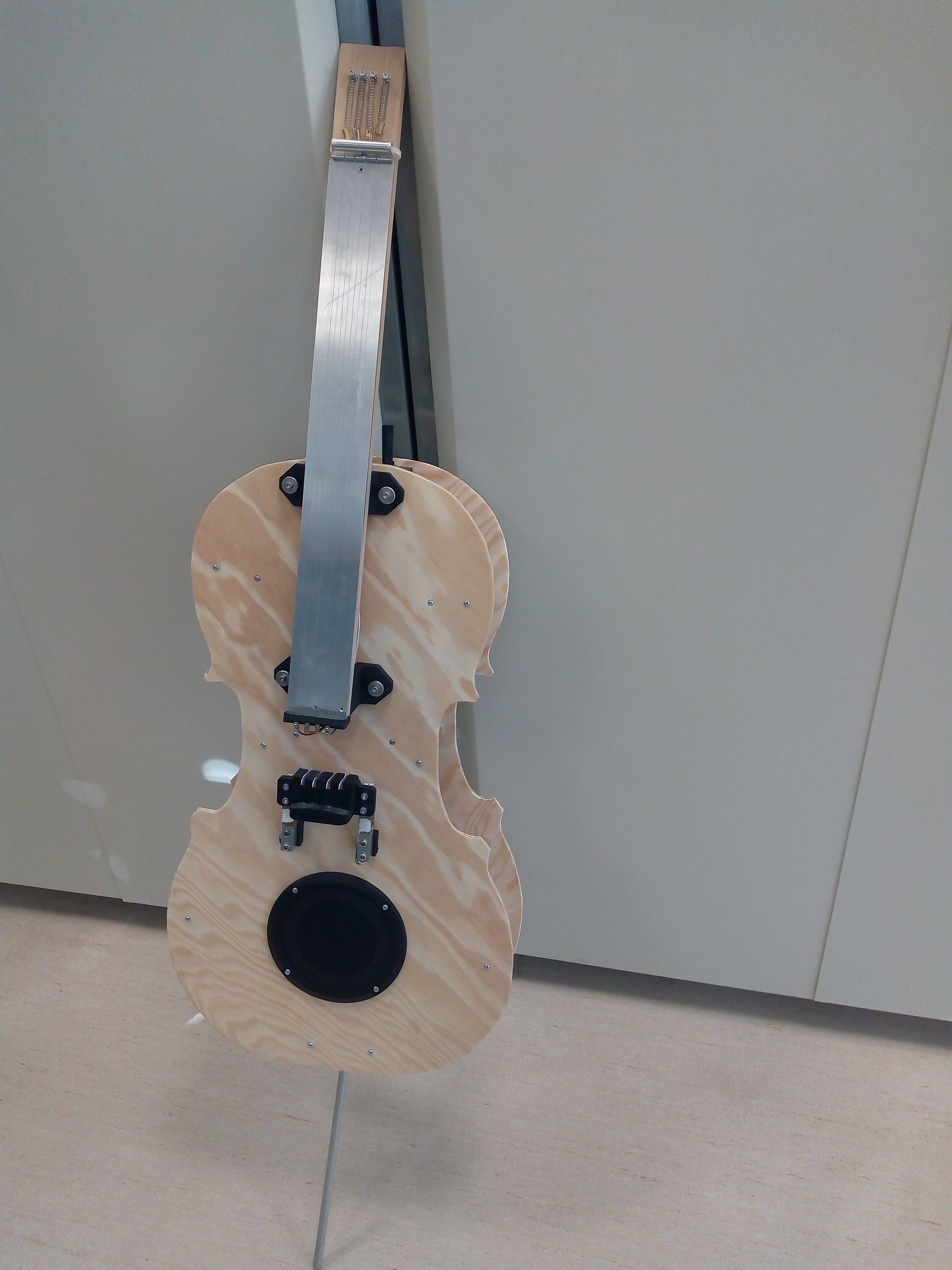
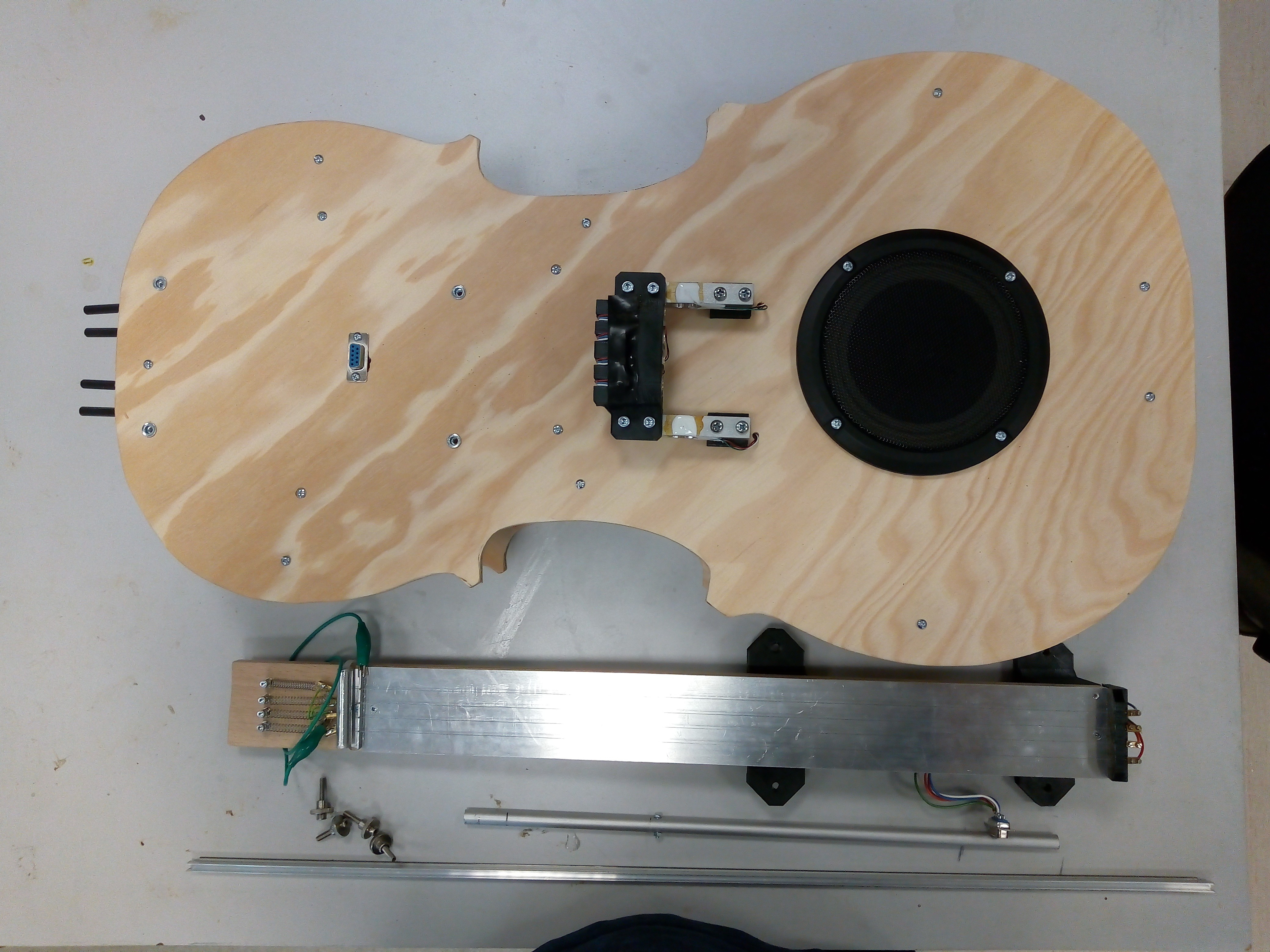
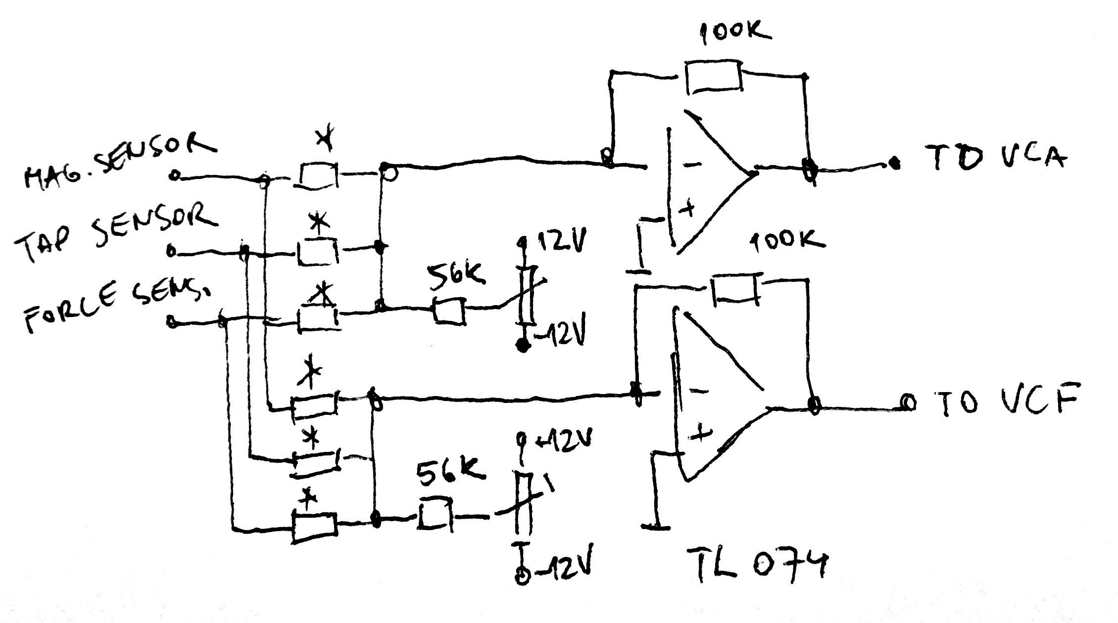
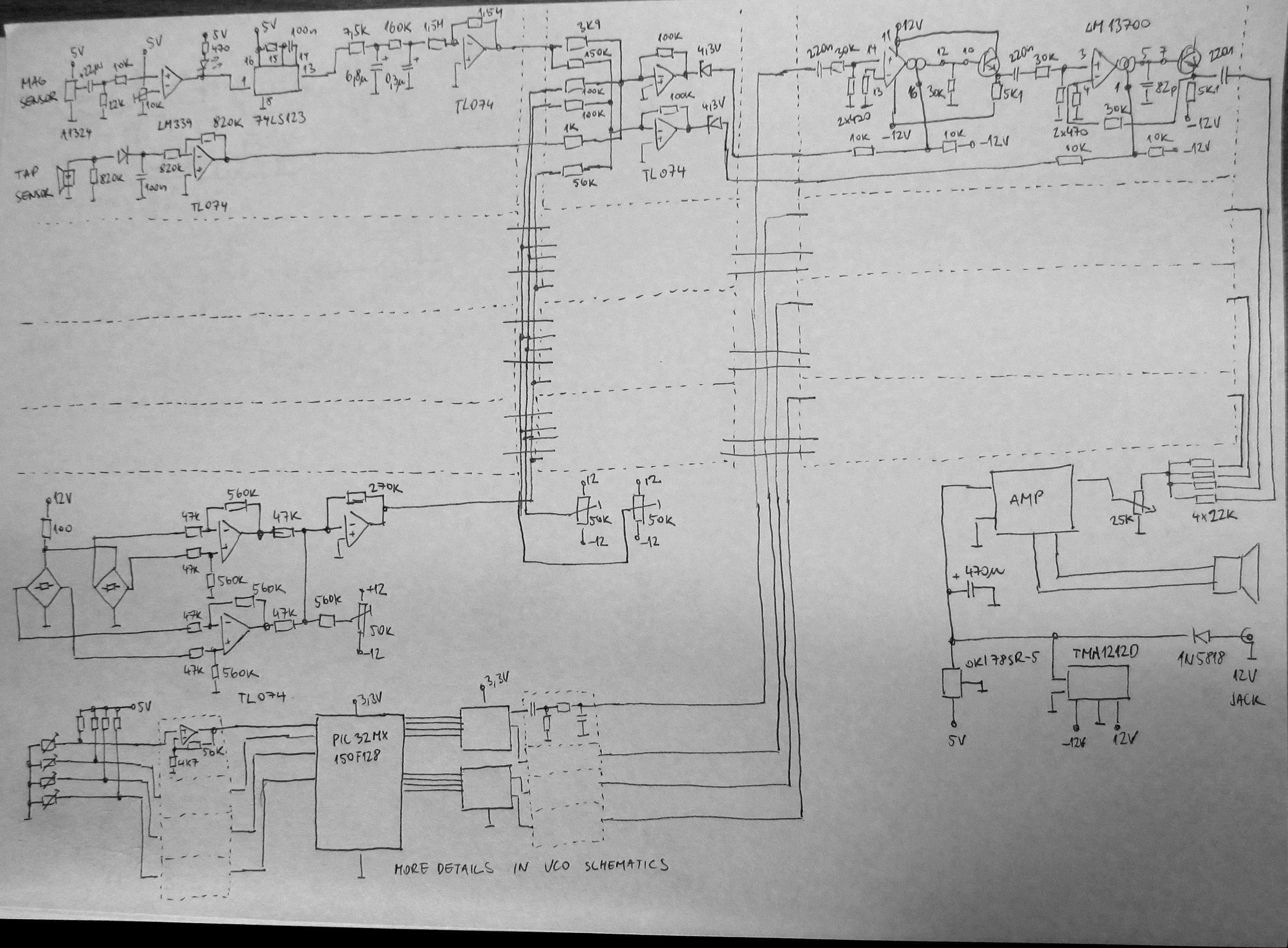
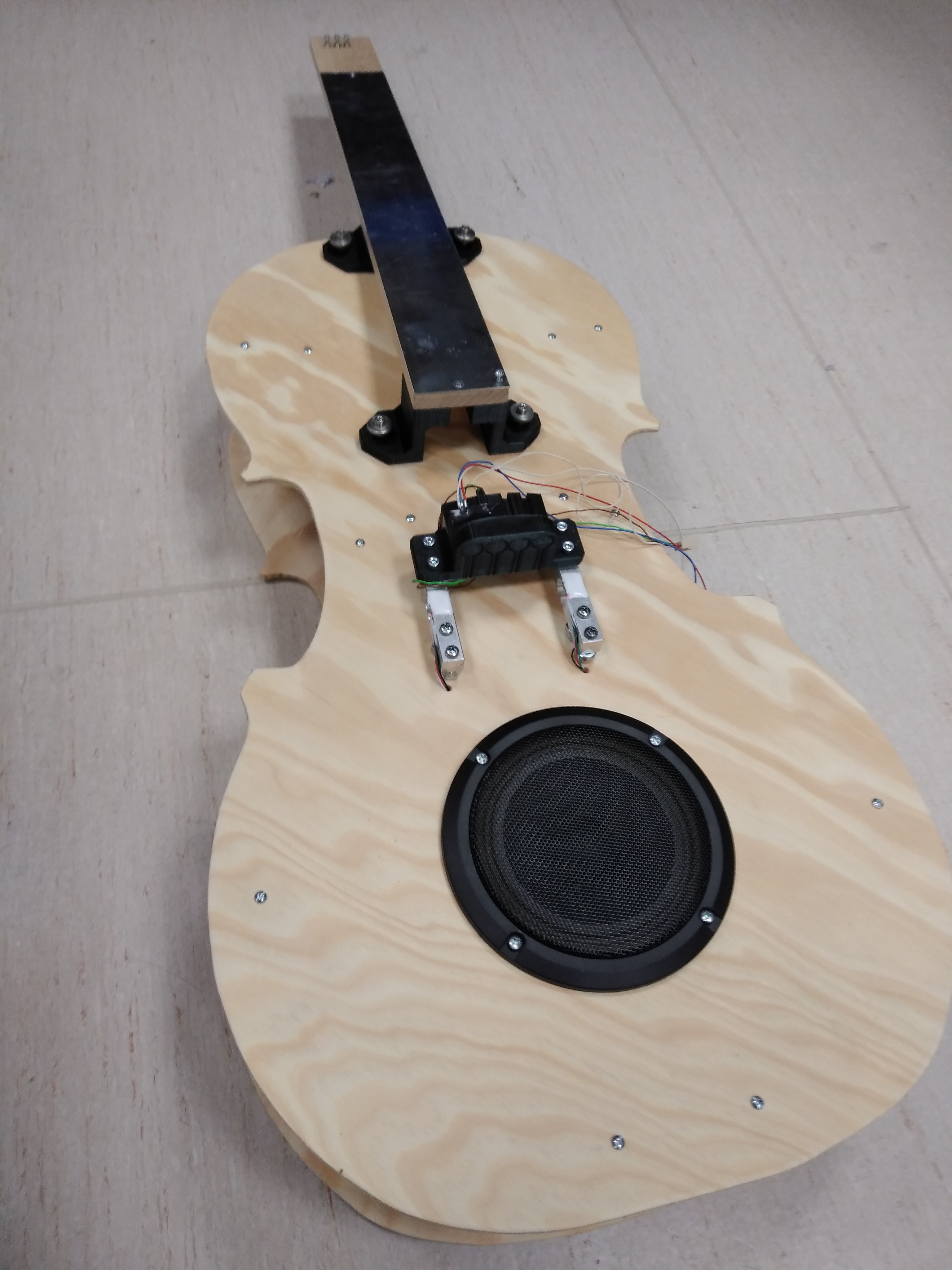
This project is four-voice, mostly analog synthesizer, trying to mimic cello - with shape, sound and style of playing. It's not the first time someone builds DIY cello synthesizer, but previous attempts had too little control of sound by player. Ideas I came with are centered to harvest as much player's input as possible - this includes not only sensing of bow movement speed, but also bow pressure and ability to play double stops (two or more strings at once) and pizzicato style (plucking the strings instead of bowing). There are strings at the fingerboard, but the strings do not oscillate at all - those are pieces of resistive wire, pressing the wire against metallic fingerboard shortens the string length (just like for cello or other string instruments), this is sensed electronically and oscillator frequency is set accordingly. Signals from sensors (magnetic sensors to sense bow speed, tap sensors and force sensor) are mixed and brought to voltage controlled amplifiers and filters to set tone volume (dynamics of playing) and spectral characteristics (tone color). Result is brought to power amplifier and played by loudspeaker.
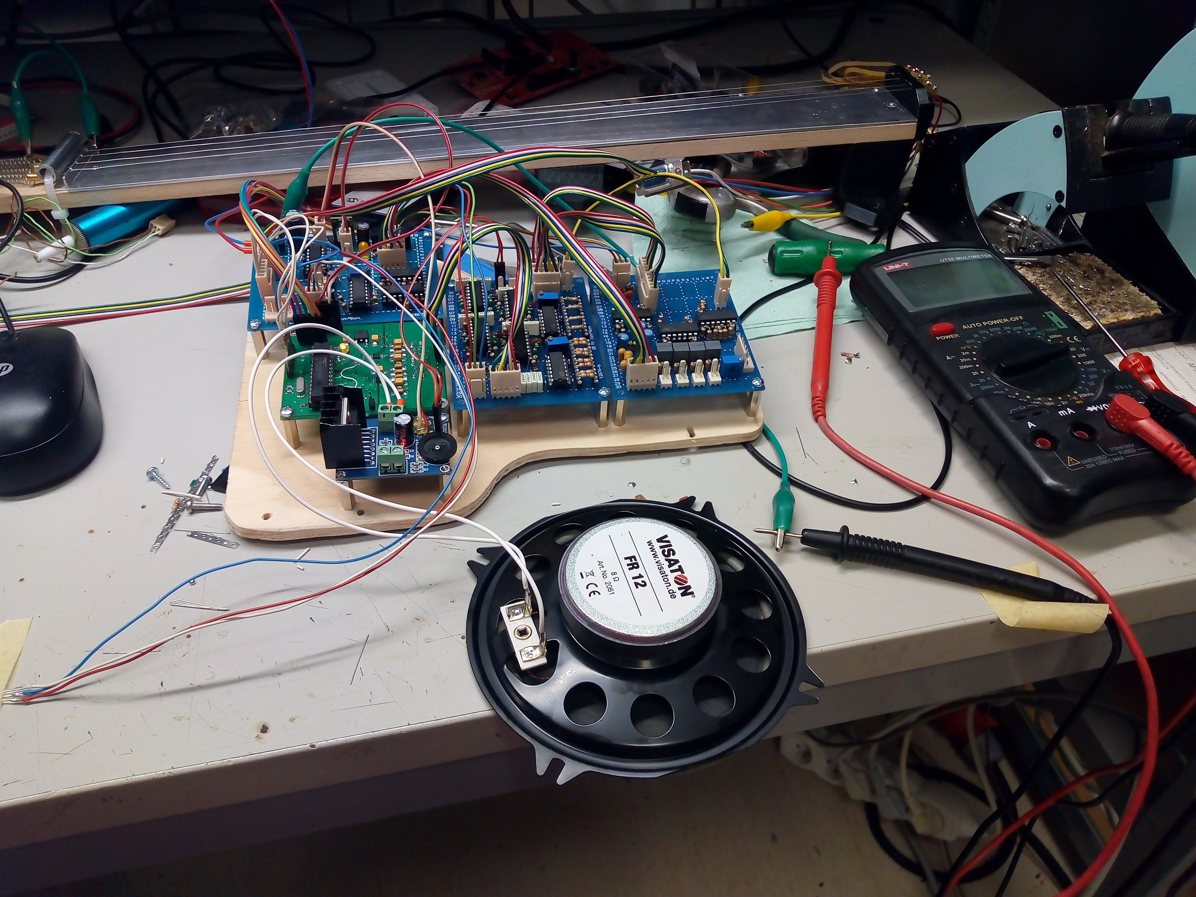
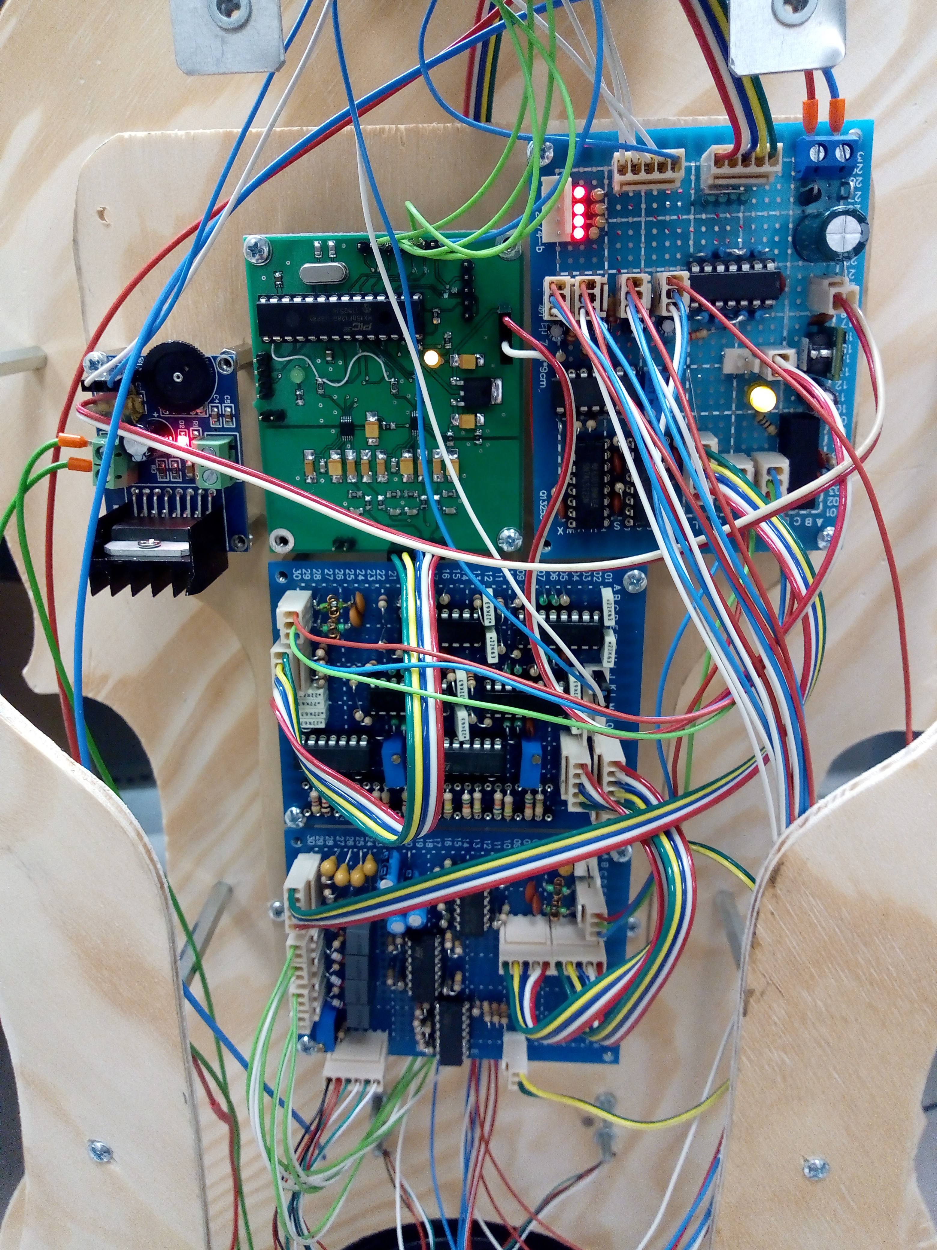
This all required some thoughts, like abusing piezo speaker as tap sensor, using magnetic measuring tape as vital part of bow, but still, this device holds more than 300 discrete components to achieve the goal - analog synthesizers were never trivial.
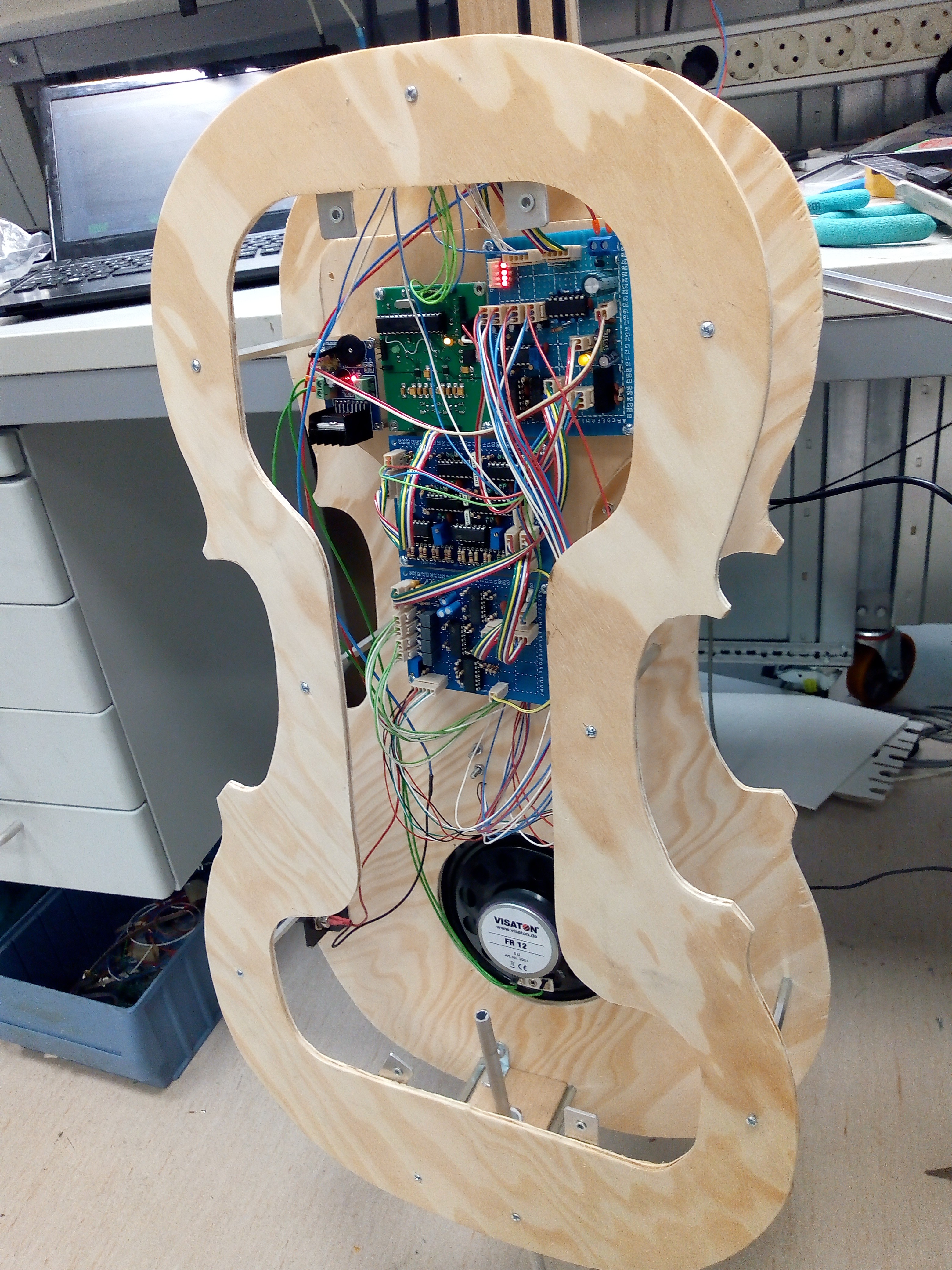
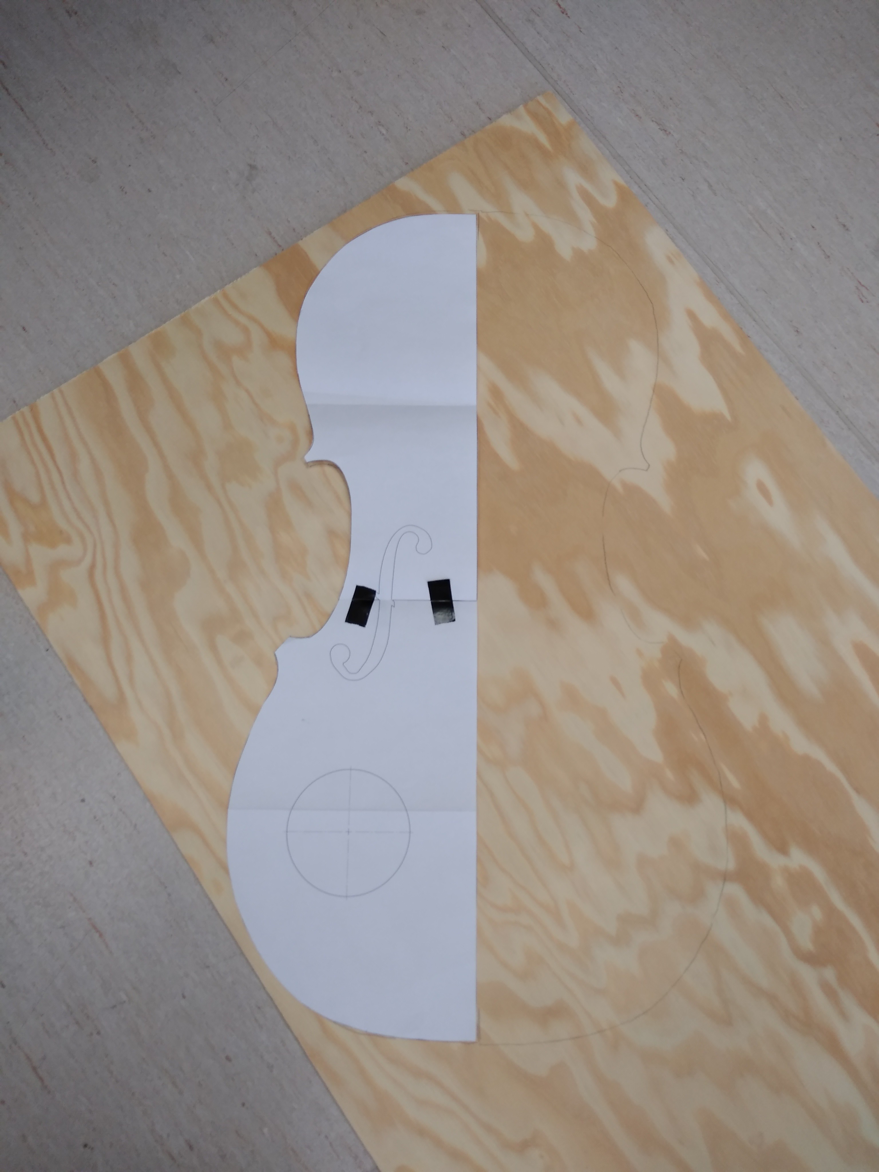
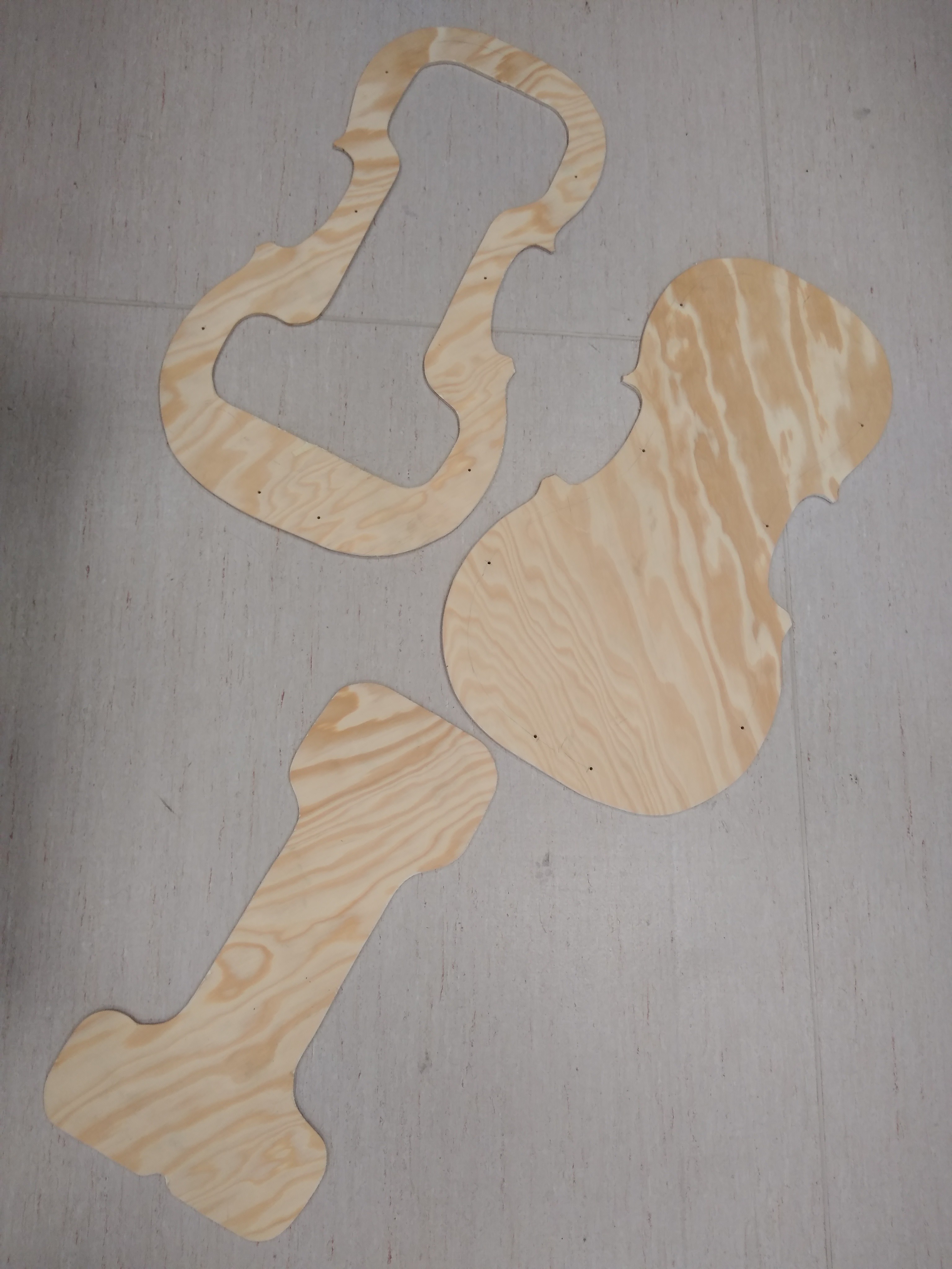
Body of instrument was made from plywood and 3D printed parts. Most of the components were manually soldered on protoboards.
In the project logs, I tried to capture the thoughts that were behind the design, as well as the build itself and documents after-the-fact, including redrawing the hand-drawn schematics into electronic form with various formats for your viewing pleasure and creating BOM. Those files were all uploaded into files section, as well as 3D model that were drawn as fist inception, holding printable objects. I spiked the project logs with photos. This all should enable anybody to understand, modify and improve my work, keeping in resonance with open-source ethos.
Despite all the thoughts and work I put into the instrument, it is still different from real cello. This is both good bad and good. Bad because cellists who are used to classic instruments, may have problem adapting to different sensitivity of instrument; good because "electronification" beyond usual magnetic pickup on classic cello brings new sonic and playing possibilities. Oh, and fingerboard with strings is completely detachable, allowing the instrument to be packed more effectively for traveling or so.
I asked trained cellist to play for a few minutes with the instrument. As expected, overriding muscle memory was not easy, but after a few attempts, it started to give in. She is really brave for entering completely uncharted waters.
Now I can see some details that can be improved later. Finding better strings is probably number one priority, allowing better contact with fingerboard and cleaner intonation. The sound is still a bit mechanic, I thoughts of fine-tuning the voltage mixer parts, as well as adding post-mixing filters to play with the sound a bit. Adding MIDI output is completely doable, too.

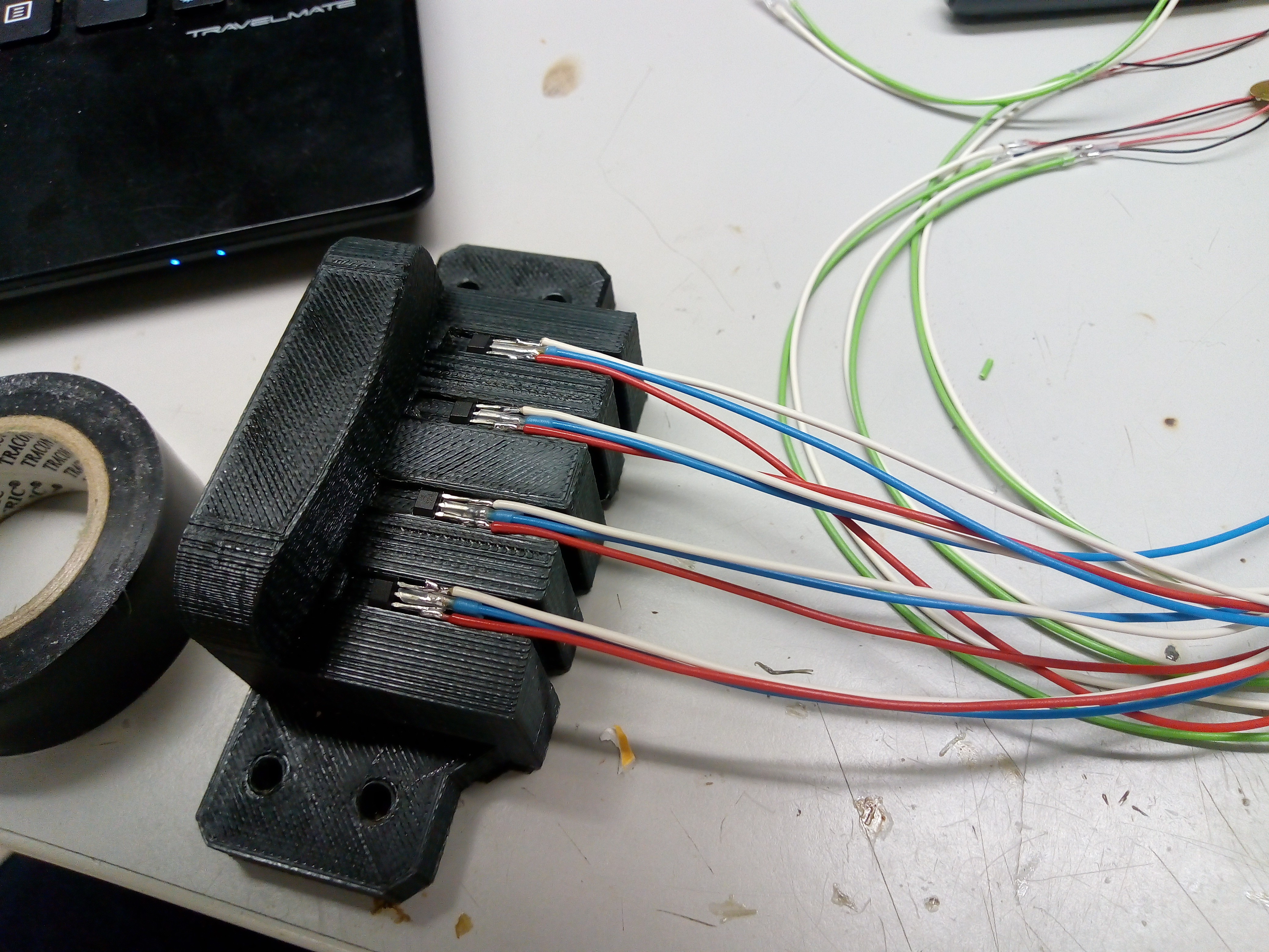
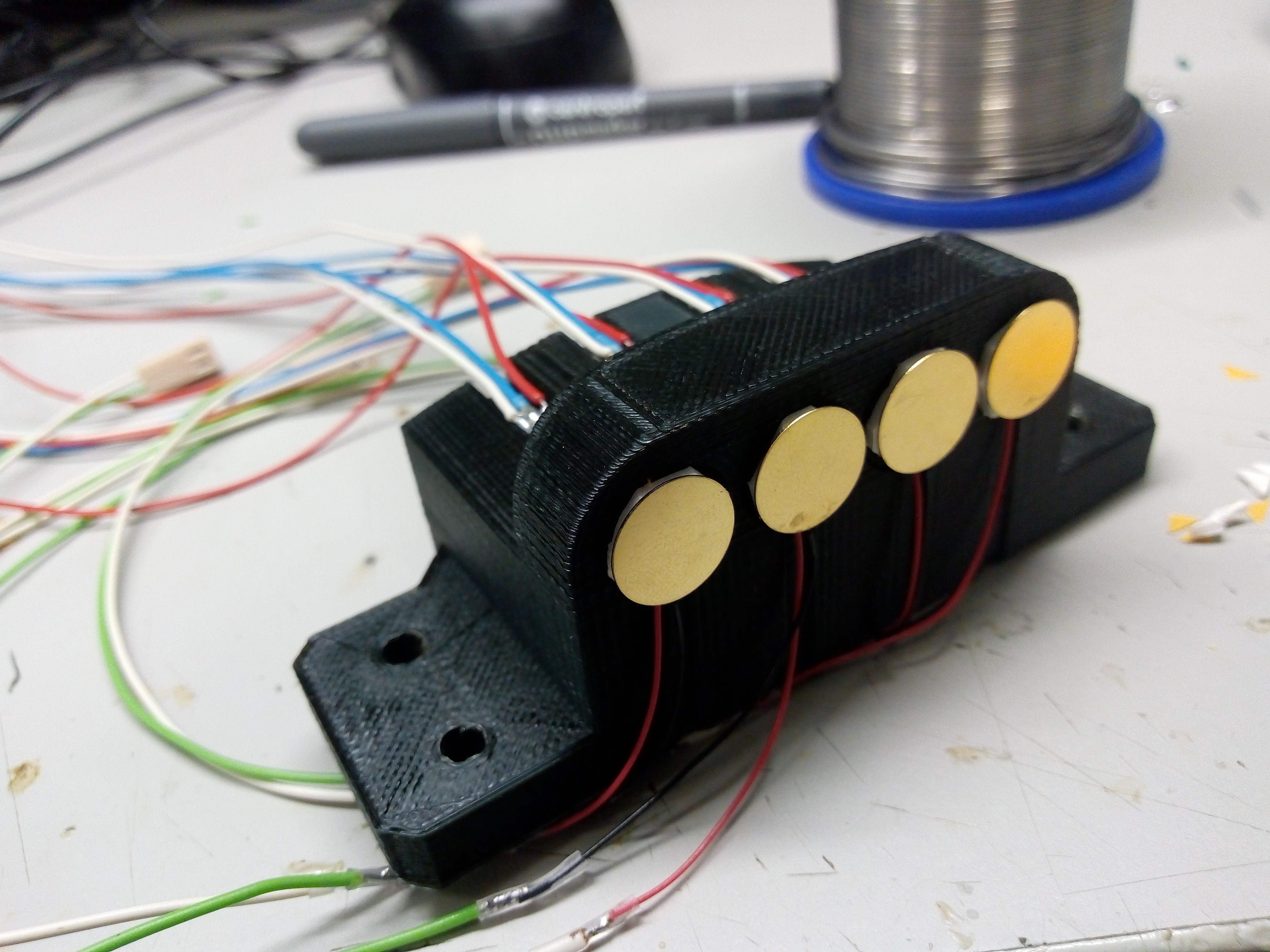
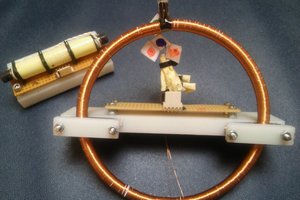
 Added are some more photos capturing bow and detail of strings fixation
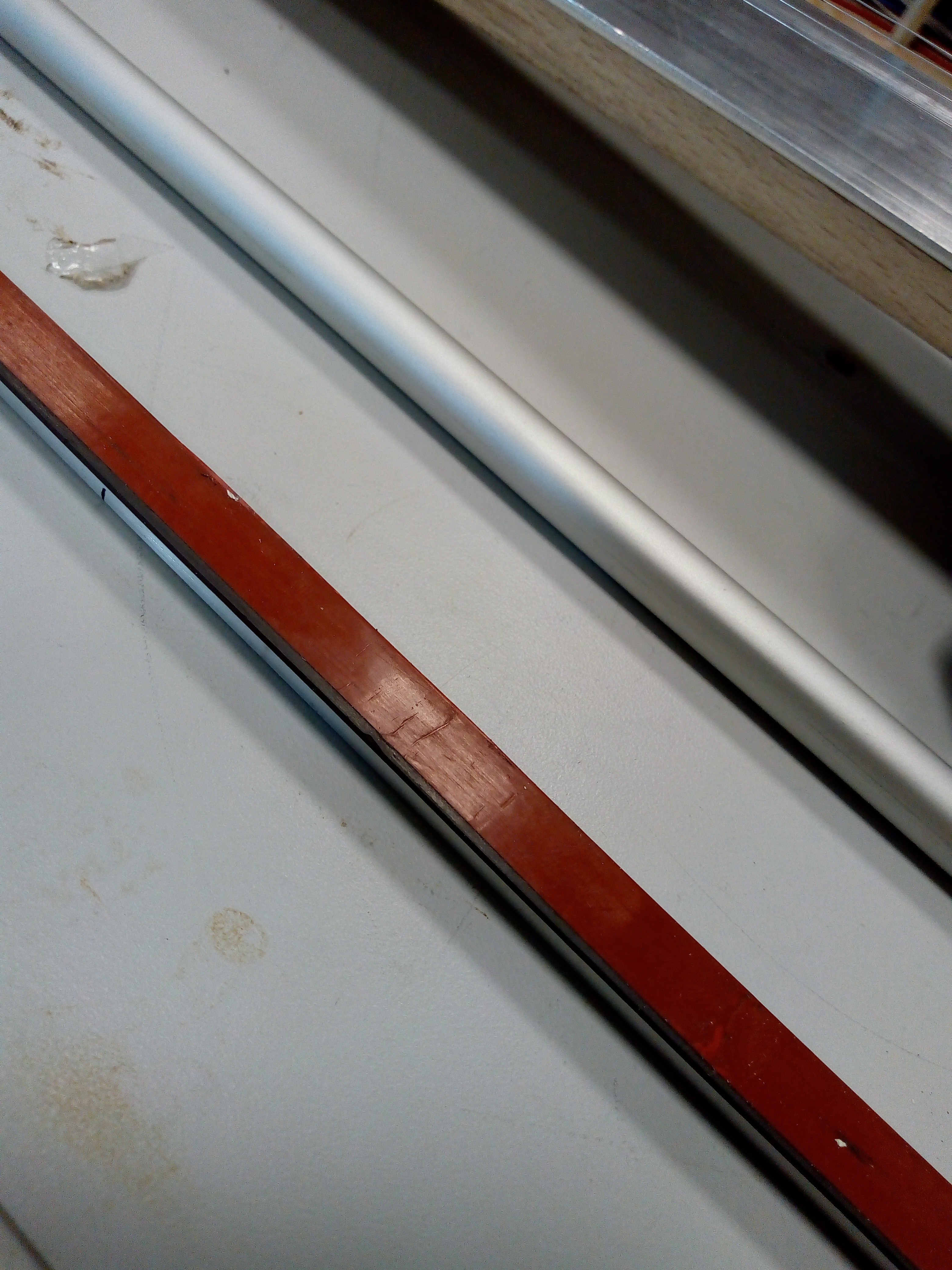 Bow is magnetic strip -
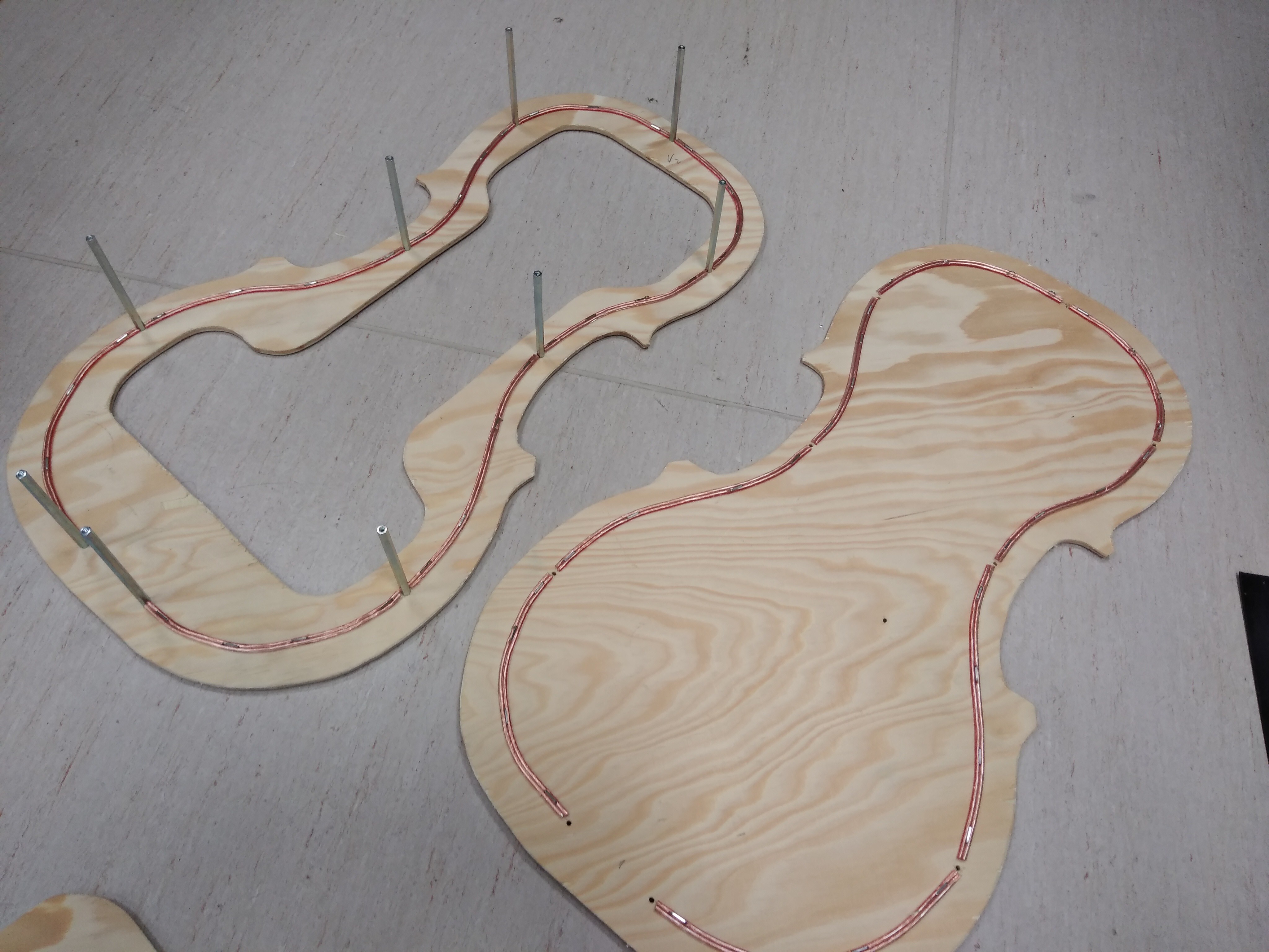
 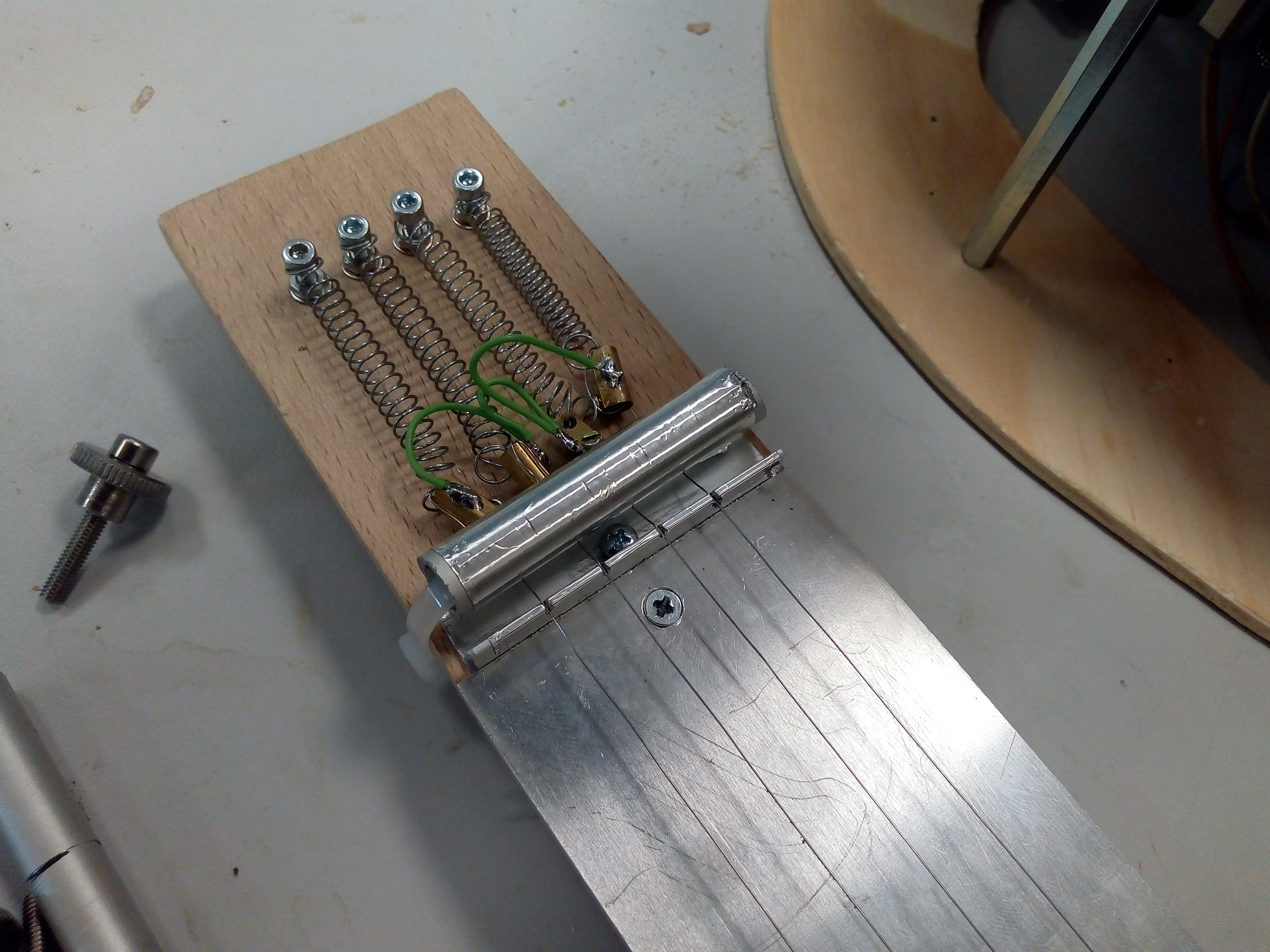 Resistor wires are fixed to steel wound strings - to keep resistor wire in mechanical tension - via brass screw terminals. Terminals are soldered together via piece of wire. I added aluminium round tube to press the strings against the end of fingerboard - L shaped aluminium extrusion with four cuts where strings of resistor wires are held in position.
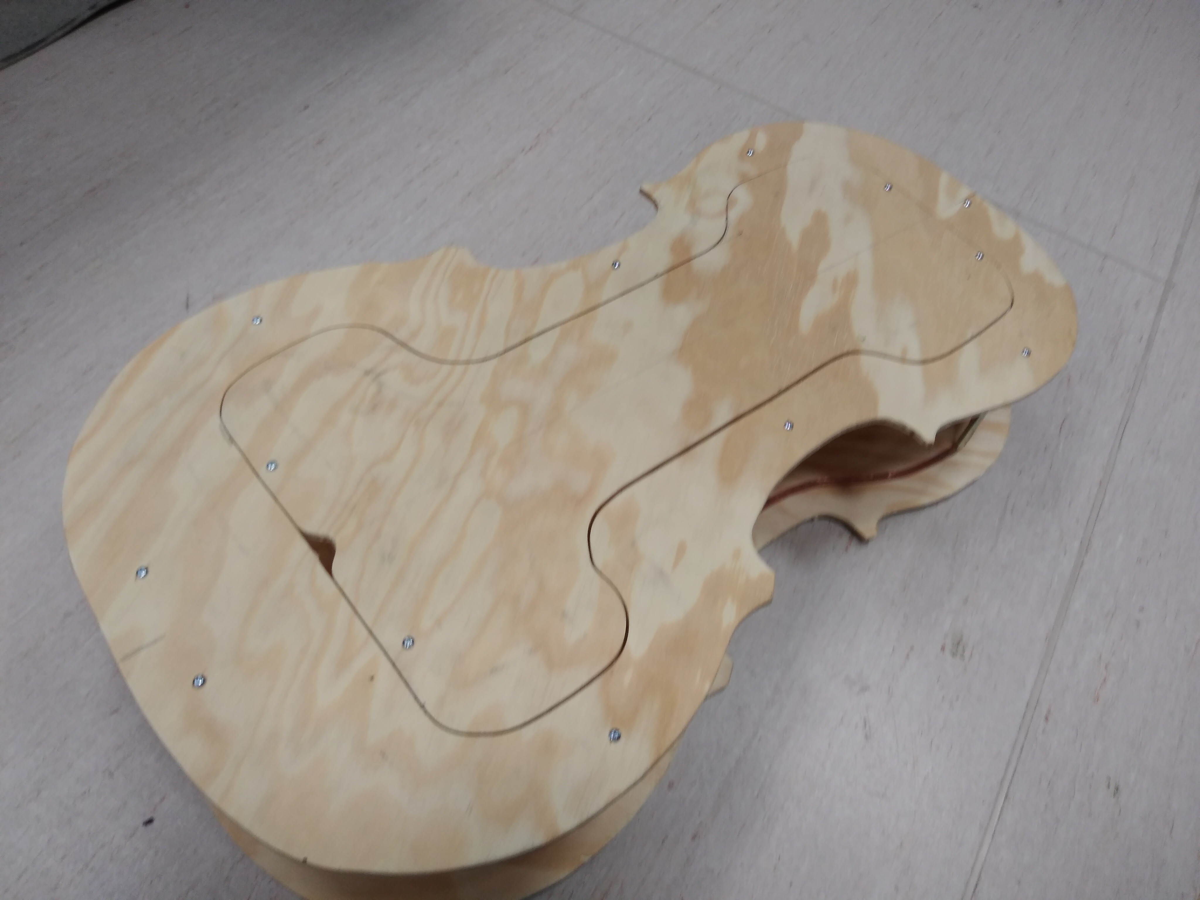
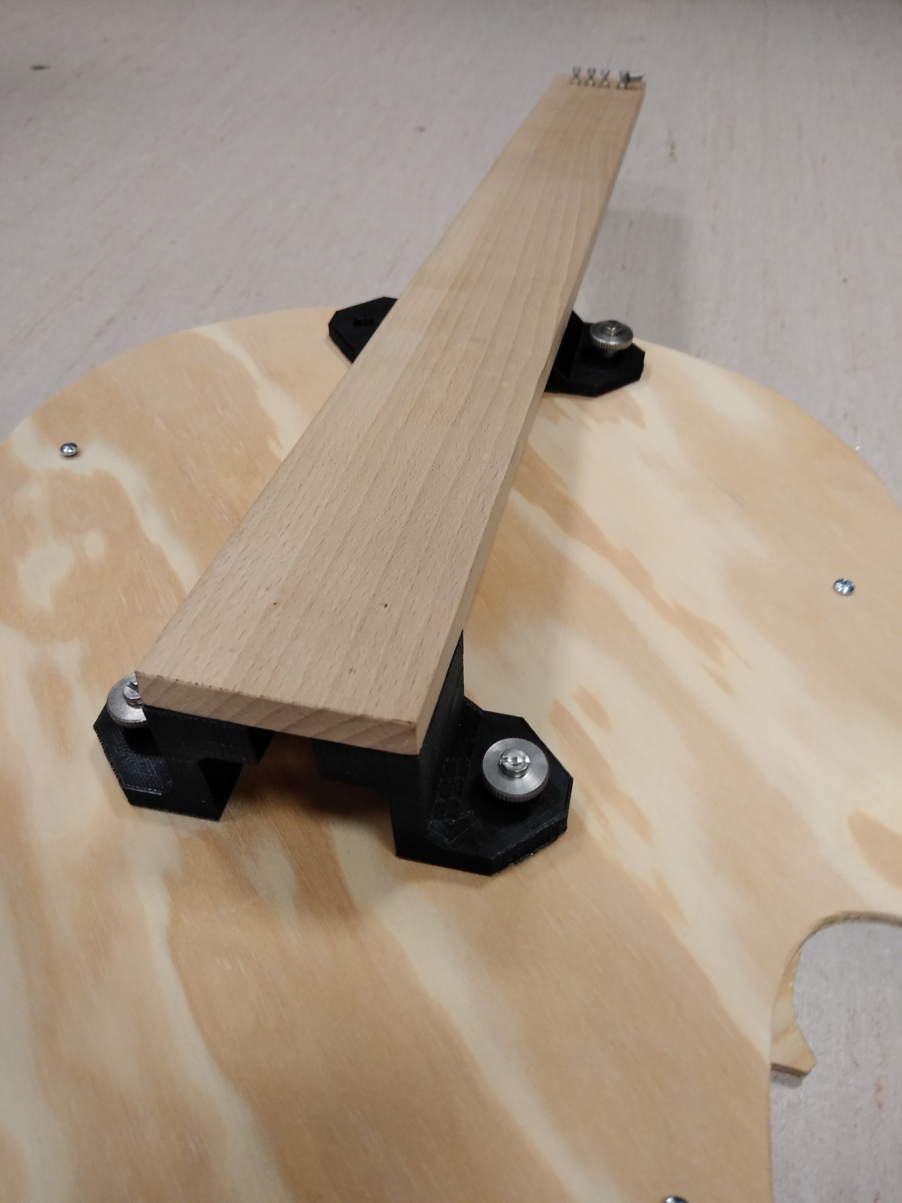
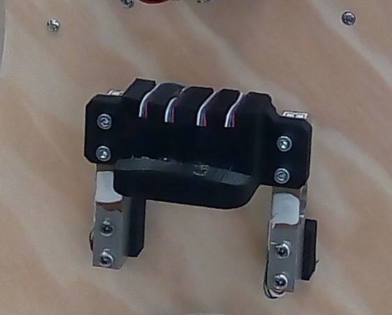
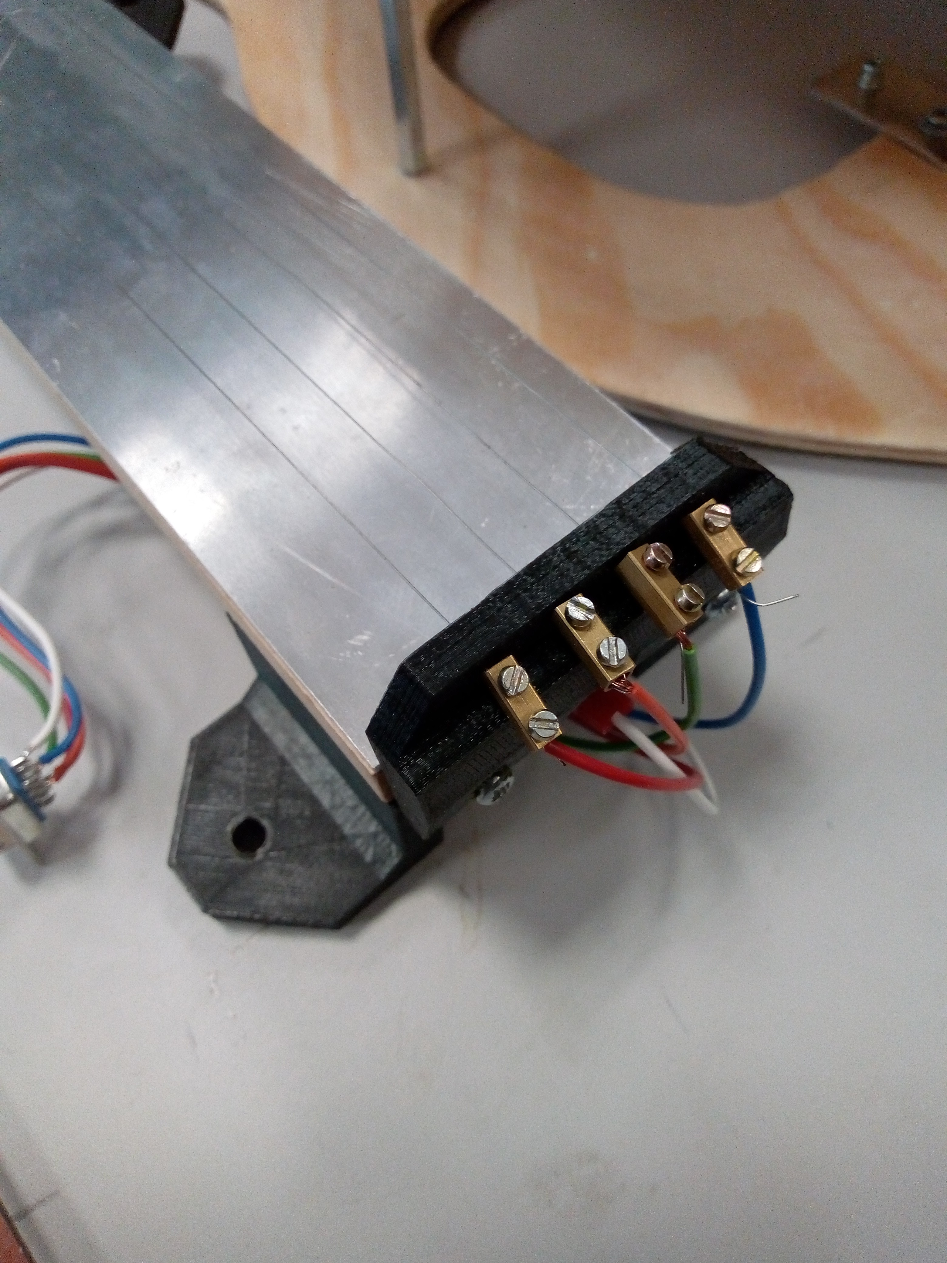 Whole fingerboard assembly is detachable, along with bottom pin, so dimensions of cello can be decreased for easier traveling or so.
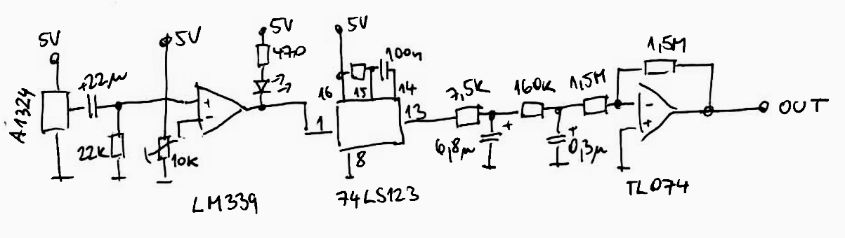 The low-pass filter is followed by inverter providing both impedance buffering as well as inverting needed for following stages.
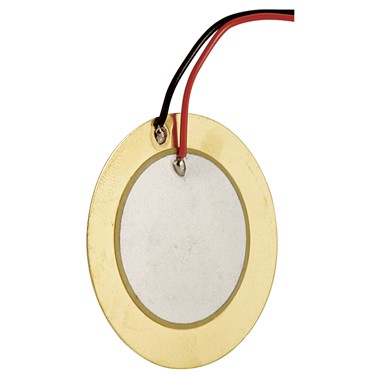 Usually those are used as sound transmitters, ie. being driven with voltage and creating mechanical output (sound). Reverse operation is also possible, where mechanical input is creating voltage signal on its terminals.
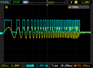
 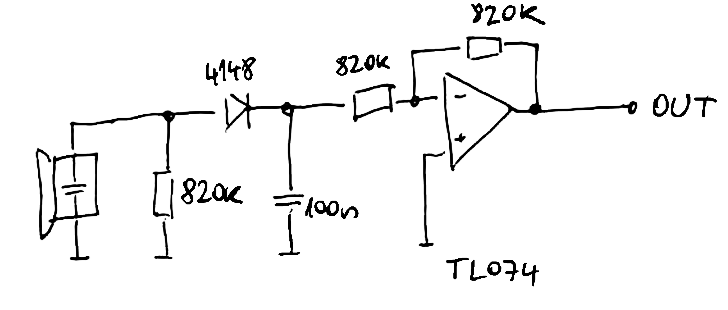 Main part of this circuit is resistor, diode and capacitor. After tapping on the sensor, voltage spike (blue waveform on picture below) charges the capacitor via diode, which is stopping its discharge when voltage on transducer is negative. Capacitor then slowly discharges into 820k - input impedance of the amplifier - see yellow waveform.
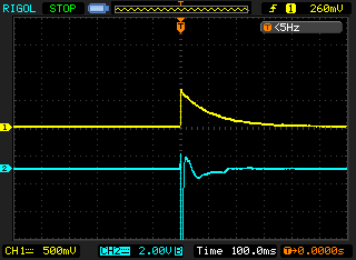
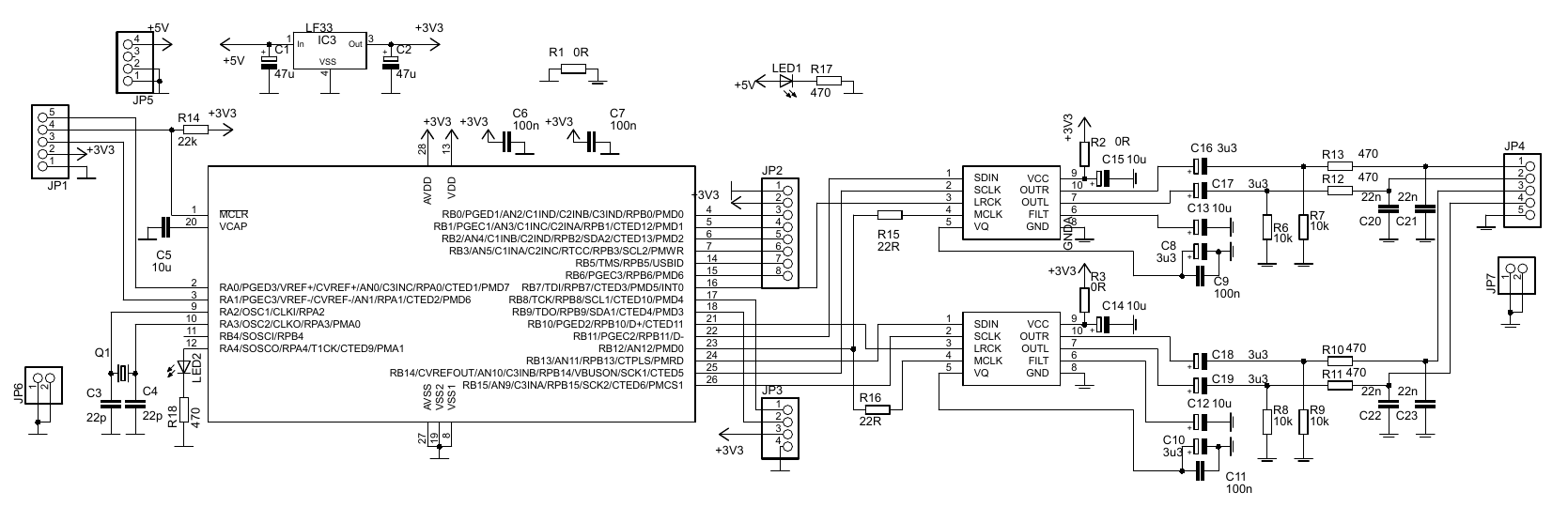 Nothing surprising here - PIC32MX150F128B is driving pair of CS4344 stereo DACs, outputting 4 mono outputs in total. SPI interfaces of the PIC are brought to I2S mode and interrupt routine is feeding the DACs with increasing value, being reset after a while - creating sawtooth waveform, available as output of four separate oscillators on pinheader JP4.
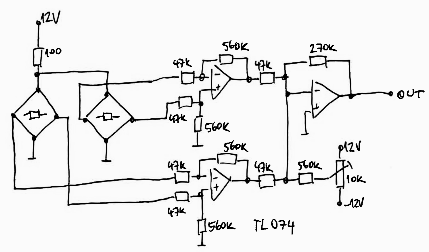
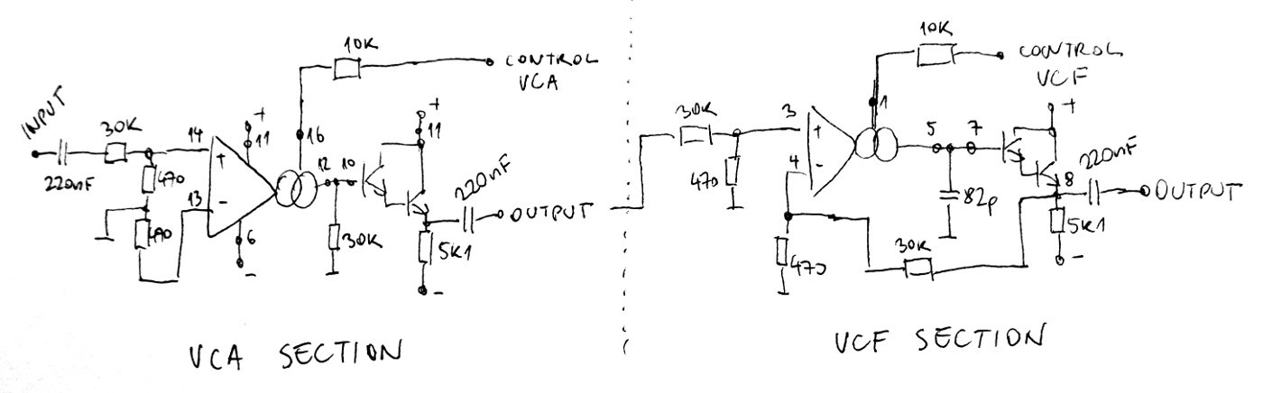 It contains two halves of LM13700 in more-less databook application. It is powered by symmetrical +-12V. LM13700 is great chip and makes non-trivial tasks quite easy, though replicating this circuit four times on protoboard is rather daunting task. In order to minimize chance of mistake, I tested out the circuit on breadboard and measure its transfer across audible range.
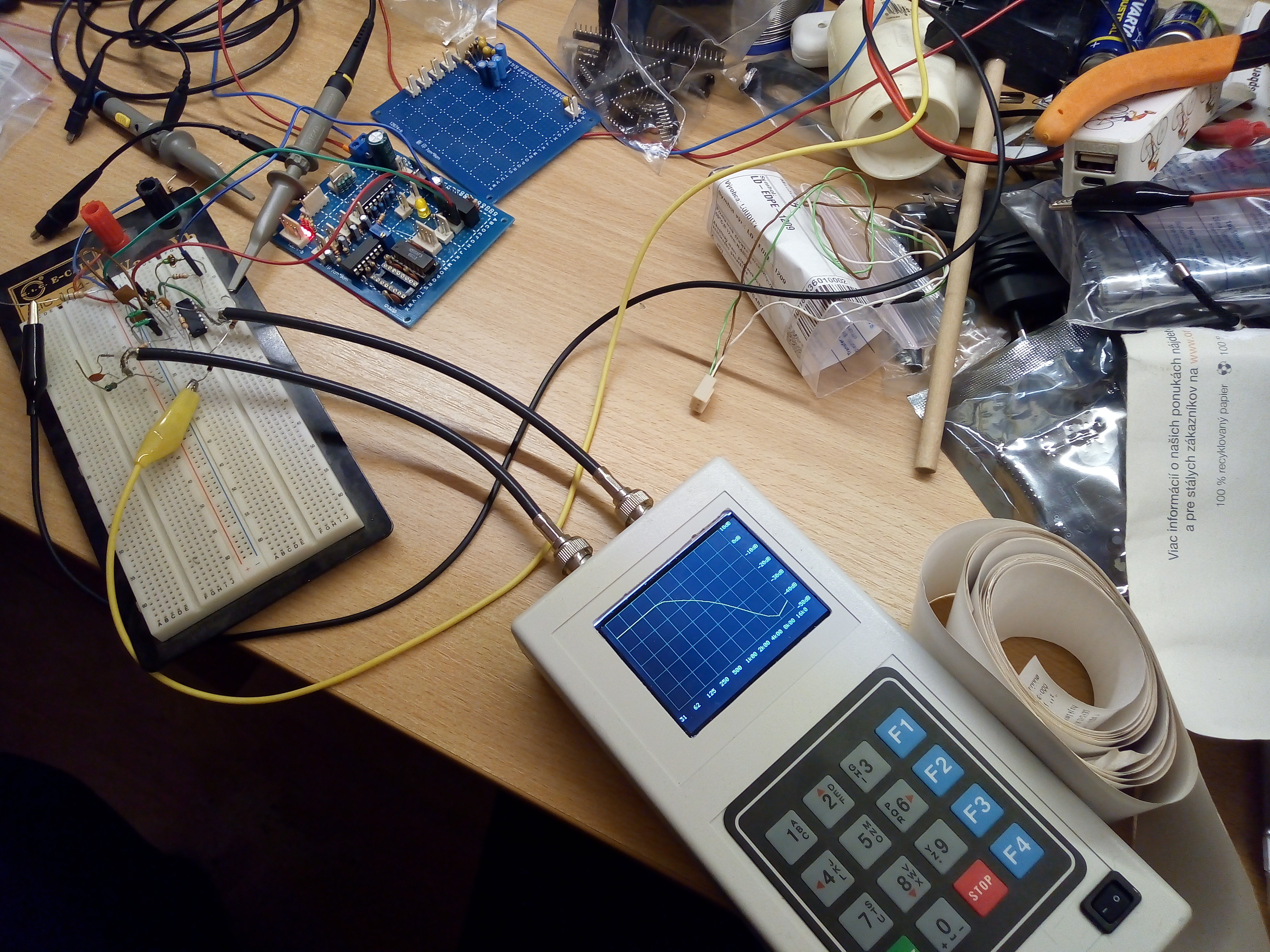 Having all three VCx blocks is fine start for instrument, but it still lacks control circuits, translating players command (bow speed, bow pressure or "string plucking") into waveforms to control those blocks.
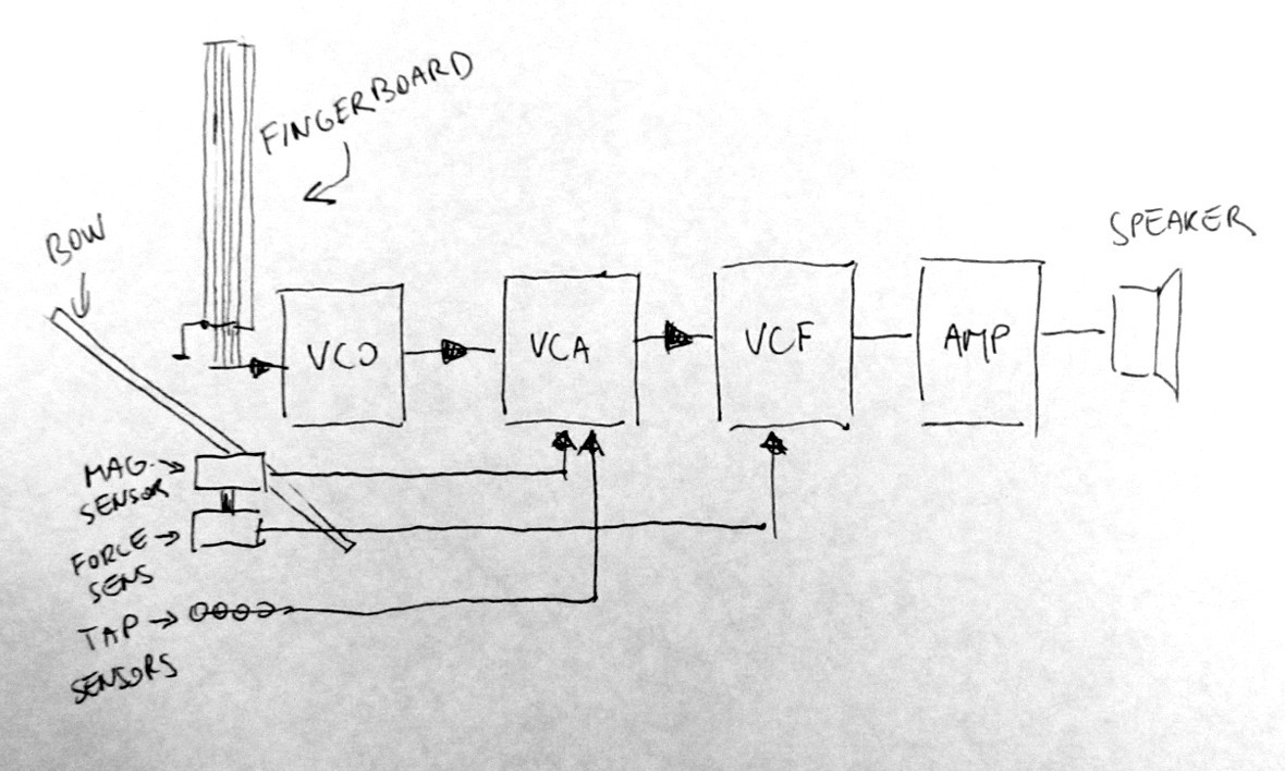
 Aron Molnar
 numero_trey
 oneohm
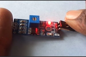
 kamalkedin123